HAL Id: insu-02043546
https://hal-insu.archives-ouvertes.fr/insu-02043546
Submitted on 21 Feb 2019
HAL is a multi-disciplinary open access
archive for the deposit and dissemination of sci-entific research documents, whether they are pub-lished or not. The documents may come from teaching and research institutions in France or abroad, or from public or private research centers.
L’archive ouverte pluridisciplinaire HAL, est destinée au dépôt et à la diffusion de documents scientifiques de niveau recherche, publiés ou non, émanant des établissements d’enseignement et de recherche français ou étrangers, des laboratoires publics ou privés.
Capillarity-driven supersolubility in dual-porosity
systems
Claudie Hulin, Lionel Mercury
To cite this version:
Claudie Hulin, Lionel Mercury. Capillarity-driven supersolubility in dual-porosity systems. Geochim-ica et CosmochimGeochim-ica Acta, Elsevier, 2019, 252, pp.144-158. �10.1016/j.gca.2019.02.026�. �insu-02043546�
Accepted Manuscript
Capillarity-driven supersolubility in dual-porosity systems Claudie Hulin, Lionel Mercury
PII: S0016-7037(19)30111-5
DOI: https://doi.org/10.1016/j.gca.2019.02.026
Reference: GCA 11141
To appear in: Geochimica et Cosmochimica Acta
Received Date: 24 August 2018
Revised Date: 4 January 2019
Accepted Date: 14 February 2019
Please cite this article as: Hulin, C., Mercury, L., Capillarity-driven supersolubility in dual-porosity systems,
Geochimica et Cosmochimica Acta (2019), doi: https://doi.org/10.1016/j.gca.2019.02.026
This is a PDF file of an unedited manuscript that has been accepted for publication. As a service to our customers we are providing this early version of the manuscript. The manuscript will undergo copyediting, typesetting, and review of the resulting proof before it is published in its final form. Please note that during the production process errors may be discovered which could affect the content, and all legal disclaimers that apply to the journal pertain.
Capillarity-driven supersolubility in dual-porosity systems
Claudie Hulin* and Lionel Mercury
Institut des Sciences de la Terre d’Orléans, UMR 7327 Université d’Orléans, CNRS, BRGM, 1A rue
de la Férollerie, 45071 Orléans cedex (France).
*
Corresponding author: [email protected].
Keywords: Pore size-controlled solubility; Thermodynamics; Metastability; Tensile water properties, Phase transitions.
Abstract
Capillary phenomena are widespread in unsaturated media such as soils, building stone, deep depleted aquifers and still gas storage/sequestration reservoirs. Processes linked to capillarity depend on pore size and environmental conditions such as relative humidity. When capillary forces are high, water’s internal pressure can reach negative values representative of a tensile state. In those
conditions, the capillary tensile water provokes compaction in moist granular materials. In geochemical terms, thermodynamics predict a significant effect on the solvent properties of tensile water. However, very little experimental work has validated thermodynamics models or shown the porosity arrangements that make capillarity a significant player to control the geochemical balance and poromechanics of porous media. In this study, we designed an experimental setup in glass microtubes (ø 200 µm) conducive to capillary tension. In the tubes, salts (halite and sodium sulfate) precipitated from an evaporating solution to build a strongly contrasted dual-porosity system. Large pore bodies (ø 200 µm) coexisted with nanometric pores that induced capillary tension in the whole volume. We observed mineral–liquid interactions (mass gain/loss, crystal shaping), especially how salt solubility changed as a function of capillary conditions. The water’s tensile state increased salt solubility, changing the reactions’ equilibrium constants at constant composition as predicted by thermodynamics. In addition, mineral grains showed clear evidence of poromechanical tensile stress, driving salts to move towards the interior of the tube or to crack. The results showed the potential significance of capillarity in heterogeneous porous media including nanopores. They should be considered in relation to how porous structures change, in the contexts of increasing droughts due to climate changes and increasing excavation work in deep sedimentary basins.
1. INTRODUCTION
Porous soils and rocks exposed to the atmosphere undergo weathering processes and erosion, which are heightened by frequent drying periods. Close to dry air, porous networks are characterized by the coexistence of air and water, and the fluid behavior is partly controlled by capillary forces. The so-called unsaturated zone (UZ) is widely present in near-surface environments, as soils and exposed rocks, as well as in engineering structures, monuments and artworks (Desarnaud et al., 2016). Global climate change, especially regarding humidity cycles (more frequent rainfall, flooding and extreme aridity, sea level rise), may directly impact behavior in the UZ and the associated weathering-erosion processes. Secondly, industrial processes such as gas injection, nuclear waste disposal and fluid removal drive deep geological formations to UZ-like states (e.g. André et al., 2014; 2015; Peysson et al., 2014; Ott et al., 2015), with possibly extremely dry (artificial) conditions.
Under drying conditions, water evaporates and the liquid–air interface retreats until it is retained in the thinnest pores by capillarity, where the internal liquid pressure decreases. The relative volume of capillary water results in poral geometry and dryness: for instance, multiscale porous networks retain larger volumes of capillary water, especially if large pores are connected through nanoscale pore throats (Fig. 1). In such a network, the nanometric capillary bridges in the pore throats generate high capillary forces that are transmitted to the whole volume of hydraulically connected water (outer pore throats and inner pore bodies) (Fig. 1). This situation can arise in sedimentary rocks (Fig. 1a), (e.g. Muller and McCauley, 1992; Wang et al., 2003; Anovitz et al., 2013) or in crustal rocks (Fig. 1b), (Holness, 1992; 1995).
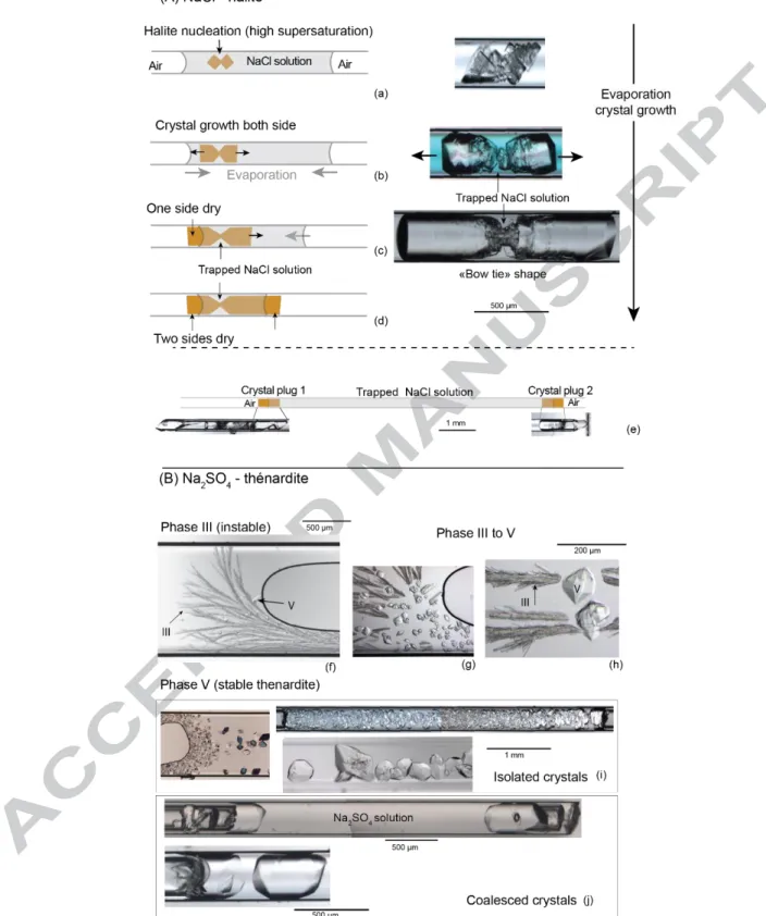
Figure 1. Dual-porosity systems. (a) in sedimentary oolithic rocks, (b) in crustal settings. (c) corresponding schematic view of a filled macropore surrounded by nanothroats (solid in brown, liquid in blue).
Evaporation of in-pore water also leads to the precipitation of salt crystals initially dissolved in the poral solution. As they grow and accumulate in the poral network, those salt crystals can clog the pores and ultimately cause damages by exerting pressure against the pore wall (crystallization pressure, e.g. Correns, 1949; Scherer, 1999; Flatt, 2002; Benavente et al., 2004; Steiger, 2005a; b; Coussy, 2006; Shahidzadeh et al., 2012). Yet, in both arid environments and those with wetting and drying cycles, salts are recognized to be responsible for the alteration of porous media (e.g. Wellman and Wilson, 1965; Cooke, 1981; Goudie and Viles, 1997). While drying processes and evaporation have attracted a lot of attention, only a few studies have focused on the role of capillarity in weathering processes. However, capillarity is recognized to provoke the compaction of granular materials (e.g. Fraysse et al., 1999), possibly inducing cracks in clays (e.g. Weinberger, 1999) and cohesive sands (Chavdarian and Sumner, 2011). This effect can also be invoked to explain certain cracks in shotcrete (Ansell, 2010) and cementitious materials (e.g. Lagier et al., 2011) and deformation observed in soft porous material (Bouzid et al., 2011b) and crystalline nano-channels (Tas et al., 2003). From the geochemical viewpoint, field observations suggest that a capillary state influences
pedogenetic evolution over millions of years, accumulating preferential anhydrous/hydrous mineral phases depending on climate cycles and mean pore sizes (e.g. Tardy and Nahon, 1985; Trolard and Tardy; 1989; 1988; Tardy, 1997). Capillary water’s thermodynamic properties can be calculated either through a water activity framework (e.g., Trolard and Tardy, 1987; 1989; Wang 2003) or by a liquid pressure approach (Mercury and Tardy, 1997a, b; 2001; Mercury et al., 2003; 2004; Lassin et al., 2005). Both models predict how the geochemical mass balance will change in any UZ holding capillary water.
The effects of capillarity are size-dependent, and so may be significant only for nanometric pores. At this scale, the capillary water is under absolute negative pressure (or under capillary tension) and able to exert a tensile force (e.g. be responsible for granular stack compaction). Nanometric pores can be quantitatively important in sedimentary rocks. Macropores are connected through nanometric pore throats (Muller and Mc Cauley, 1992; Anovitz et al., 2013) as in Figure 1. Water retained in the large pore bodies surrounded by nanothroats can reach and sustain the same negative pressure as the nano-capillary water in the pore throats before water cavitation.
Our laboratory experiments studied the physical and chemical behavior of water-solid interactions in such situations. We developed a set-up based on an existing protocol (Fig. 2; Bouzid et al., 2011b; Røyne & Jamtveit, 2015) where a bimodal pore system conducive to capillary tension was built. Cylindrical microtubes were filled with a saline solution that evaporated in drying conditions. The solution became supersaturated with respect to its solid, which precipitated on both air–liquid interfaces (highest salt concentration). The salts grew until forming a cylinder that apparently clogged the tube, but a thin nanometric film persisted between the crystal and the glass wall (Fig. 2a). This film is assumed to have a zero contact angle with the silica walls, so the meniscus diameter is equal to the thickness of the open space. If the solution-air interfacial curvature became large enough to equilibrate with the imposed relative humidity (as expected from the Kelvin equation), capillary forces prevented evaporation and generated negative pressure in the entire trapped solution including the macrovolumeThe entire volume of solution was in a tensile state (Fig. 2b), which is supported by the final bubble nucleation appearing inside the trapped macrovolume (Fig. 2c). The water under tension was in a metastable state (superheated) until the nucleation of vapor returned the system to its most
stable state (liquid–vapor assemblage at saturated vapor pressure). After bubble nucleation in the pore body, the liquid internal pressure is brought back at the atmospheric value. Consequently, there is no more pressure gradient across the liquid-air interface, which becomes flat (Fig. 2c).
.
Figure 2. Main experimental steps (see text). (Modified from Bouzid et al., 2011b)
This method turns the initially monosized “saturated” microtube into an unsaturated bimodal pore system prone to high capillary conditions. Our goals were to experimentally validate the geochemical signatures of capillarity and to show that dual-porosity media can contain large capillary volumes.
2. MATERIAL AND METHODS
2.1 Materials
Micro-capillaries with 200 µm internal diameter (VitroTubesTM) were filled with a saline solution (NaCl or Na2SO4) that evaporated under controlled relative humidity.
NaCl and Na2SO4 aqueous solutions were prepared from NormaPur powder and distilled water.
The NaCl solution was at 5.5 mol.L-1 (24.3 wt %) and had a relative supersaturation n/n0 = 0.90
(molality at saturation n0 = 6.15 mol.L -1
at 20°C). The Na2SO4 solution was at 3.5 mol.L -1
(33.3 wt %), so undersaturated with respect to thenardite (relative supersaturation n/n0 = 0.64 at 20°C) and
supersaturated with respect to mirabilite (relative supersaturation n/n0 = 1.19 at 20°C). The saline
crystallites. This means that there are no or very few potential seeds in the solution, so that during evaporation, the solution will reach a high supersaturation before crystals nucleate(Desarnaud et al., 2014).
The evaporative demand, leading to evaporation or capillary conditions, was set by controlled relative humidity (RH) in a climate chamber (HPP108, Memmert technology). The preferred RH was 48%, to be compared to the equilibrium RH of a NaCl saturated solution (75.3%, Greenspan, 1977) or of a Na2SO4 solution (93%, Winston and Bates, 1960). This RH gradient enables a moderate drying
rate promoting the precipitation of massive salt (Desarnaud et al., 2014) when the appropriate supersaturation was reached, at constant temperature. The microcapillaries were regularly observed using an optical microscope (Leica DM2500) in a room thermostated at 20°C. Observations were made in transmitted light using lens with 5x, 10x, 20x and 50x magnification. Pictures were captured with a Leica DFC295 digital camera allowing image resolution of 3 megapixels (2048 x 1536) and pixel size of 1.2 µm x 1.2 µm with a 5x magnification lens. To avoid any heat transfer, we reduced exposure to microscope lights to the minimum possible, so we can consider heating due to light as negligible.
2.2 Methods
Three types of experiments (Fig. 3; also supp. info.) were carried out, differentiated according to: - two lengths of liquid column trapped in between the crystal plugs: long and short,
corresponding to large and small volumes of tensile water;
- two types of initial solutions, based on NaCl and Na2SO4 electrolytes, because the solvent
properties of the associated crystals phases are different when the water is in a tensile state. The NaCl-short solution systems (Fig. 3a-d) were made from a highly supersaturated solution, using plasma-cleaned tubes (15 min) and filtered solution. This made the halite nucleate inside the solution and grow rapidly on both sides with a symmetric hopper (skeletal) shape (Sunagawa, 1999; Desarnaud et al., 2014) (Fig. 3a). First, when the supersaturation was still high, several cubes of halite nucleated and crystallized on each other, with growth parallel to the tube. As the supersaturation decreased, the salt continued to grow at each side preferentially onto the inner wall of the tube. As the
solution kept on evaporating, the salt continued to grow on each side and not in the middle, because at this point the solution was trapped and did not evaporate. This explaining the “bow-tie” shape (Fig. 3b-c). The solution on each side continued to evaporate until reaching first one side of the crystal (Fig. 3c) then the other (Fig. 3d). The liquid air interface stopped receding since no air entered in the trapped solution. We built 26 “bow-tie” systems.
For the long-NaCl solution systems (Fig. 3e), the NaCl solution was left to evaporate until reaching high supersaturation, without any crystal nucleation or growth. Then we broke the tube on each side close to the air–water menisci. This induced rapid evaporation at both liquid–air interfaces and led to the precipitation of two opposite crystals along the interfaces. The two crystals grew rapidly and apparently clogged the tube, trapping the large volume of solution (from 6.9 to 51 mm long, so from 0.157 to 1.88 mm3 in volume). As in the bow-tie shape systems, the trapped solution did not evaporate. Twelve of these systems were built.
Figure 3. Crystallization sequences to build double plug systems (see text).
Concerning Na2SO4, no useful distinction was made by tube length, so the experiments were
33.3%wt solution, undersaturated with respect to thenardite (anhydrous stable phase) and supersaturated with respect to mirabilite (decahydrate stable phase). After evaporation, the salt first crystallized into a dendritic metastable phase III (Fig. 3f) then transformed into stable phase V, thenardite (Fig. 3g-h), as commonly observed (Steiger and Asmussen, 2008; Shahidzadeh and Desarnaud, 2012). The crystallization sequence resulted in numerous thenardite crystals in solution (Fig. 3i), which coalesced to form plugs (Fig. 3j). The formation of massive plugs was encouraged by using highly saline solution (33.3% wt) introducing high salt mass. Ten such systems were built.
3. RESULTS
The dual-porosity systems were built in 48 tubes (table 1) either with one bow-tie shaped halite crystal (Fig. 3d), or with two distinct crystals (halite or thenardite). In each system, after the liquid–air interface receded and reached the external side of a crystal (Fig. 2b), we observed no further air entry in the trapped macrovolume. The liquid–air interface remained in the narrow space between the salt plugs and the glass wall and stopped evaporating. After one external side of one crystal was dry (and only after), we observed different reactions in the trapped volume: salt dissolution, gas nucleation and solid displacement. Over time (up to 2 years), we carefully monitored the events occurring within the trapped solution and/or affecting the crystal plugs.
Exp type
No final gas nucleation
Number of exp Solid motion Salt dissolution Gas nucleation
Time before gas
nucleation No changes
Only solid motion
NaCl-short 26 0 16 20 2 days to 3 months 6
NaCl-long 12 4 1 5 4 days to 3 months 5 2
Na2SO4
10 0 0 10 20 days to 3 months 0
Total 48 4 17 35 - 11 2
Table 1. Summary of dual-porosity systems and major observables (also suppl. info.).
3.1 Gas nucleation
The most common reaction, observed in 35 systems, was the formation of a gas bubble in the trapped solution after a certain amount of time – from several hours to months – after at least one of
the external sides of the salt(s) was dry. This gas nucleation has already been observed and was not the result of air entry (Bouzid et al., 2011b). Figure 4 illustrates two experiments in which gas nucleated in a solution trapped between two thenardite crystals (Na2SO4). In the first experiment, gas nucleated 20
days after the external side of the right crystal dried (Fig. 4A) and in the second experiment, gas nucleated two months after the external sides of both crystals dried (Fig. 4B).
Figure 4. Gas nucleation in a Na2SO4 solution trapped by two thenardite crystals. (A) 20 days after one external side
of the salt was dry (B) 2 months after both external sides of the salt became dry.
We observed gas nucleation in the trapped solution in bimodal pore systems built with NaCl (halite) and Na2SO4 (thenardite). In each of the 10 systems built with thenardite, gas nucleated from 20
days to 3 months after at least one external side of the salts dried. In systems built with halite crystals,
we observed gas nucleation in 25 of the 38 experiments: in 20 of the 26 bow-tie shape systems (Fig. 3a-d), and in 5 of the 12 systems built with two distinct salts (Fig. 3e; see also supplementary information).
3.2 Inward movements of salt crystals
With two of the NaCl-long systems, crystal plugs were seen to move (Fig. 5).
Figure. 5. Salt plug inward motion, evidenced with the large displacement of the left salt crystal that comes to an end with bubble nucleation.
In both cases, we observed the inward motion of one or both salt plugs until a gas bubble appeared in the trapped solution. In the experiment shown in Fig. 5, the crystal on the left slid over 3.3 mm in four days (Fig. 5b-c). When a gas bubble appeared on the right (Fig. 5d), the crystal stopped and never moved again. In the experiment shown in Fig. 6, both salts moved inward for seven days (Fig. 6, step a to c) before a gas bubble nucleated (Fig. 6, step d). The salt on the left moved over 3.3 mm while the opposite one (on the right) moved over 0.13 mm (see the closer view 2, Fig. 6).
Figure 6. Salt traction during the 7 days after both salt plugs precipitated, trapping the saline solution. At the top: pictures of four stages of the experiment. Below: closer views of the salt plugs: the crystal on the right (closer view 2) first dissolved (step b) and then slightly reprecipitated (step d). At the bottom: illustration of the first three stages of the experiment for a better understanding. Step (a): salt plugs precipitated and entrapped the saline (NaCl) solution. Step (b): after 7 days, the crystal on the left has moved inward over 3.3 mm, while the one on the right has moved over 0.13 mm and been dissolved (see closer view 2). Step (c): gas nucleated in the trapped solution and the salts stopped moving and dissolving.
3.3 Dissolution of halite
3.3.1. Dissolution and traction
The moving crystal on the right in the NaCl-long experiment had been partially dissolved before the gas appeared (Fig. 6A, closer view 2). The simple cylindrical geometry of the system allowed us to measure the volume of the trapped solution and the total mass loss. The dissolved length of halite was 130 ± 13 µm, corresponding to a volume of 4.1.10-3 ± 0.4.10-3 mm3, and therefore a mass loss of 8.9 ± 0.9 µg (calculated with a halite density of 2.17 g/cm3). The distance between the two salt plugs before (Fig. 6A, step a) and after crystals moved (Fig. 6A, step b) was respectively 10 ± 0.2 mm and 6.6 ±
0.2 mm, corresponding to a solution volume of 0.32 ± 0.01 mm3 and 0.21 ± 0.01 mm3 . Furthermore, a close examination of the same halite plug after the bubble nucleated showed clear lengthening over time, evidencing a reprecipitation process: the process appeared reversible.
3.3.2. Bow
-tie shaped systems
Whereas salt dissolution was only observed in one experiment built with two distinct salts (large double plug systems, Fig. 3e, j), significant salt dissolution was observed in 16 of the 26 experiments
built with bow-tie shape halite (Fig. 3A). Dissolution affected the salt in contact with the trapped solution at the thinnest part. In most cases, the bow-tie crystal was separated into two pieces and both pieces became rounded (Figs. 7 and 8, steps c and d).
Figure 7. (A) Salt dissolution in the trapped solution after one external side of the crystal (on the right) encounters air – photos and interpretative sketch. (a) The NaCl solution evaporates. (b) Bow-tie shape crystal growing in the evaporating solution. (c) After 10 days, the right side of the crystal is dry. (d) Dissolution of the thinnest part of the salt in contact with the trapped solution.
Twenty of the 26 experiments built with bow-tie shaped halite showed gas nucleation after a certain period, between 5 days and several months (section 3.1). Gas nucleated in each of the 16 cases displaying salt dissolution, and there were no cases where salt dissolved after gas nucleation.
Dissolution in bow-tie shaped crystals lasted between 5 and 45 days. In most of the cases dissolution time was 10 to 15 days.
Due to the complex geometry of the bow-tie halite crystals, we could only calculate the volume of solution and the mass loss in one case (Fig. 8B). The volume of the trapped solution was estimated at 13.10-3 ± 1.3.10-3 mm3, and the mass loss of solid salt at 1.1 ± 0.1 µg (Fig. 8B).
Figure 8. (A) System with two trapped compartments of saline solution. (B) Estimation of salt loss and volume of solution outlined by the red line drawn around the crystal (c and d).
3.3.3 The case of thenardite
In Na2SO4 systems, we observed neither dissolution nor movement of the thenardite crystal.
However, as in NaCl systems, a gas bubble appeared in the trapped solution, from one day to months after one or both salt plugs dried (Fig. 9). A closer view of both surrounding salt plugs did not show any mass change with respect to the initial situation: no significant dissolution occurred during those two months.
Figure 9. Absence of visible salt mass change in Na2SO4 double plug systems. Double arrows (red and white) on the
closer view show that salt mass had not changed (one color = one size).
3.4 Plug cracking
Another interesting observation was made with Na2SO4 double plug systems, at the critical moment
when one salt plug dries. In this experiment we cut the tube (Fig. 10, step a), enhancing the evaporation of the saline solution. After around ten minutes, the liquid–air interface reached the salt plug (Fig. 10, step b) and became confined in the small space between the salt plug and the tube wall. As the interface continued to recede between the salt and the tube wall, cracks appeared and propagated on the crystal surface along preexisting discontinuities (probably the mark of crystal coalescence).
Figure 10. Crack development observed after a crystal plug dried (a) The tube is cut close to an immersed salt plug. (b) The liquid-air interface retreats and reaches the crystal which becomes dry (c) Cracks grow from the discontinuities on the crystal surface (see closer view in (b)).
4. DISCUSSION
4.1 Tensile state and tensile stress
4.1.1 Gas nucleation and capillary film
The presence of a capillary film along a nano-scale space between the solid plugs and the tube walls is a first assumption of this work. We aspire to measure the properties and/or thickness of this film but have not achieved this yet. The Young-Laplace law (suppl. info.) gives the pressure drop across a curved interface between two phases. With concave air–liquid interfaces, the liquid pressure is lower than the air pressure, and increases as interface size decreases. This interface is itself related to the pore size by the value of its contact angle with both supporting solids (supp. info). As a second assumption in the calculations, the contact angle between the liquid and the solid host is assumed to be zero.
The thermodynamic driving force towards capillarity comes from air’s RH when below the saturated vapor pressure (suppl. info.). If the water–air surface is flat, low RH drives evaporation that increases the local air vapor pressure. In small pores, low RH can drive the liquid to decrease its
internal pressure (the water is in capillary state). If the local pore size is sufficiently small, the liquid– air interfacial curvature becomes large enough to equilibrate water and dry air (Kelvin equilibrium is reached). The liquid pressure can decrease according to the Young-Laplace law (eq (2), suppl. info.).
Consequently, the decrease in liquid pressure, driven by dry air, is controlledand limited by the size of the nano-throats and is identical in the entire hydraulically connected volume. Yet the macropores are so large that they cannot prevent the boiling of tensile water. The formation of a sphere of vapor of radius r brings the system to its most stable state which gains energy equal to with P the pressure of the tensile liquid and Psat the saturation vapor pressure). However, the creation of the
vapor-liquid interface of radius r requires an activation energy equal to (with γ the liquid–vapor
surface tension). According to the Classical Nucleation Theory (CNT), the competition between these two opposite effects results in an energy barrier Eb:
(1) which is the minimum energy required to create a sphere of vapor of critical radius r (e.g. Debenedetti, 1996, Caupin and Herbert, 2006). In nanothroat, the size is too small for the vapor nucleus to reach the critical radius required for vapor nucleation. In contrast, the adjacent connected macropore is much larger than the critical radius, enabling vapor nucleation at any time. Before that, the occluded tensile water is metastable (superheated) during a limited lifetime that decreases with the superheating intensity, which is directly depending on .
During the course of our experiments, we observed vapor nucleation in 35 on 48 microtubes after a superheating period ranging for a few days to years.
At the nanoscale, repulsive forces are caused when a fluid sandwiched between two solids undergoes the overlapping of surface force fields emanating from the facing solids (e.g. Derjaguin et al., 1987). This disjoining effect accounts for the open film, even in the presence of a supersaturated solution (e.g. Desarnaud et al., 2016). However, impurities, wall roughness and excess supersaturation, for instance, could initiate precipitation of microcrystals that would seal the open film and totally clog
the tube. This process could explain the absence of any change in the system, including gas nucleation, in six NaCl-short and 5 NaCl-long experiments (Table 1; supp. info). Water in the macrovolume would simply be trapped, without any capillary forces to put it under tensile stress, and therefore without gas nucleation, enhanced dissolution, or plug motion. It is worth saying that two NaCl-long experiments first showed slow inward halite plug motion for 3.5 and 7 months. Once the plugs stopped, no gas nucleation happened in the following year, meaning that the trapped macrovolume of solution can maintain a tensile state for a long time.
4.1.2 Mechanical effects
The inward motion of salt plugs (Figs 5 and 6) demonstrates that the crystals did not obstruct the tube and were mechanically free to move. This is consistent with the macrovolume of solution having a tensile state before vapor nucleation. As vapor nucleated, the stretched water relaxed its tension, becoming unable to exert any tensile forces on the salts. In the two experiments where salt plugs moved inward, the two salt plugs moved differently (Fig. 5) or only one salt plug moved (Fig. 6). The liquid must exert an isotropic and homogenous tension in the macrovolume, but the friction forces between the glass wall and each solid plug should have been different, probably because each crystal had its own surface roughness.
The plug cracks observed at the thenardite surface (Fig. 9) are assumed to be the result of capillary tension exert by the nanometric liquid–air interface. Cracks appeared as the nanometric interface receded between the salt and the tube wall, several minutes after we cut the tube. Therefore, the cracks were not related to the mechanical procedure of cutting the tubes. These cracks revealed the mechanical constraints exerted by the liquid against the solid surface. Yet the tensile stress in liquid is isotropic, so the mechanical effects depend primarily on the strength of the solids themselves. The glass wall was probably unaffected because of its high mechanical resistance. The thenardite crystals may have cracked because of the preexisting defects linked to the coalescence formation process (Fig. 9). Considering texture heterogeneity of pore walls in natural rocks, especially discontinuity in the structure or dislocations, even low tension can have strong mechanical effects.
We used two easy methods to ensure that the Na2SO4 that crystals were thenardite (anhydrous
crystals) and not mirabilite (decahydrate crystals). First, mirabilite rapidly dehydrates in microcrystals of thenardite in contact with dry air with RH of 93% or less (equilibrium vapor pressure of mirabilite). This event is very characteristic and easily recognizable. As the experiments were conducted at 48% RH, mirabilite must dehydrate, so we can directly identify the crystals during the experiment. Secondly, mirabilite dissolves at 32.4°C (e.g. Steiger and Asmussen, 2008). To be sure that the salt plugs were thenardite, at the end of experiments we heated the sample in a Linkam stage. As the crystal plugs did not dissolve above 32.4°C, we confirmed that the crystals observed were indeed thenardite. This has been confirmed using XRD analysis on two tubes containing Na2SO4 salts that we
identified as thenardite from morphology, behavior in dry environment, and heating.
4.2 Supersolubility effect
The dissolution of halite demonstrated that the trapped solution was becoming undersaturated with respect to halite. As temperature and composition remained constant, the change necessarily relates to the reaction’s equilibrium constant. This change is attributed to the liquid pressure decreasing toward negative values, which is consistent with the other observations, like gas nucleation and salt plug traction. The tension was imposed by capillary forces settled by one or two nanometer scale menisci surrounding the macrovolume of solution. Thermodynamics involving capillarity (Mercury and Tardy, 1997 a, b; 2001; Mercury et al., 2003; 2004; Lassin et al., 2005; see also supp. info) predict how the equilibrium constant of any reaction changes when the liquid pressure changes.
(2)
KP, K0 are the equilibrium constant for reactions interacting with capillary and bulk liquid respectively,
V° is the ionic volume of the subscribed phase at infinite dilution, n is the number of H2O molecules
involved in the reaction (from 0 for halite to 10 for mirabilite dissolution), R is the gas constant and T is the temperature in kelvin. The equilibrium constant KP in capillary conditions was calculated
considering that the chemical potentials of solids kept their values at atmospheric conditions (suppl. info.).
The increase of solubility of halite, thenardite, and mirabilite can be calculated according to equations (2), (3) and (4). For halite, the solubility S is the square root of the solubility product K, so
(3) with the halite solubility in capillary conditions (negative pressure P) and the halite solubility
at atmospheric pressure. For thenardite and mirabilite, the solubility S is the cubic root of the solubility product K, so
(4)
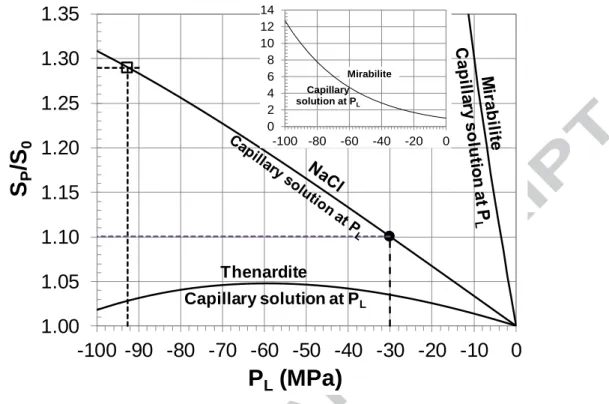
The solubility ratio of halite, thenardite and mirabilite are reported in Fig. 11 as a function of
Figure 11. Thermodynamic change in equilibrium constant with increasing tension in the interacting aqueous solution. The black circle and hollow square show the positions of the extreme liquid tensions accounting for the enhanced dissolution respectively observed with NaCl-long (Fig. 6, 30 MPa) and NaCl-short (Fig. 8, 93 MPa) experiments.
The geochemical behavior can be readily interpreted considering the volume properties of the solutes under tension (Mercury et al., 2003; also suppl. Info.).
By calculating the mass of dissolved halite, it was possible to calculate the tension required for the new equilibrium constant. For that, we assumed that the halite + liquid system had reached the new equilibrium imposed by capillary tension. If so, the increased concentration we calculated with the mass loss corresponds to the increase in halite solubility. In some experiments (Figs 7 and 8), the dissolution stopped largely before gas nucleation, supporting this assumption. In others, gas nucleated while the solid plugs were dissolving, meaning our calculations gave a minimal tension value, probably underestimated.
In two experiments (Figs 6 and 8), the tension could be estimated because of the simple geometry of crystal plugs and liquid macrovolume. In the NaCl-long experiment (Fig. 6), 8.9 ± 0.9 µg of halite dissolved in a volume of solution of 0.21 ± 0.01 mm3. Considering the assumptions stated above, this
1.00
1.05
1.10
1.15
1.20
1.25
1.30
1.35
-100 -90 -80 -70 -60 -50 -40 -30 -20 -10
0
S
P/S
0P
L(MPa)
Thenardite Capillary solution at PL 0 2 4 6 8 10 12 14 -100 -80 -60 -40 -20 0 Mirabilite Capillary solution at PLcorresponds to an increased mass concentration of 43 ± 7 µg.mm-3 which corresponds to an increased solubility of 12 ± 2% ( . The first assumption was that activity coefficients do not
change with the increasing concentration linked to the higher solubility. The second assumption is that the system reached equilibrium during the observation time: both the macropore volume and the halite plugs retained their characteristic sizes. The thermodynamic model predicted a tension of 36 ± 6 MPa (Fig. 11, black circle shows the minimal tension 30 MPa). To reach that tension, the liquid–air interface must have a curvature radius of 2.4 ± 0.4 nm and a thickness of 4.8 ± 0.8 nm if the contact angle is equal to zero.
In one NaCl-short experiment (Fig. 8), 1.1 ± 0.1 µg dissolved in 13×10-3 ± 1.3×10⁻³ mm3 of solution, corresponding to an increased mass concentration of 86 ± 16 µg.mm-3. This corresponds to an increased solubility of 24 ± 5% ( due to a tension of 75 ± 18 MPa (Fig. 11,
hollow square shows the maximum tension 93 MPa). To reach that tension, the liquid–air interface must have a curvature radius of 1.4 ± 0.3 nm and a thickness of 2.8 ± 0.6 nm if the contact angle is equal to zero. In this case, the solid dissolution stopped two weeks before gas nucleated, in close agreement with the assumption that the system had reached a new equilibrium state.
In most of the NaCl-short experiments, the amount of dissolved salt could not be calculated because of the complexity of the crystal shape and of the liquid volume. However, the increased solubility was clearly evidenced by the dissolution of the central part of the mono-solid, leading to two distinct halite plugs. This observed dissolution of the central part of the mono-solid is also consistent with minimizing surface energy of the solid-solution interface.
It is noteworthy that water and aqueous solutions can sustain even higher tensions (100 MPa and beyond) in closed microcavities than the presently recorded capillary tensions (30 to 93 MPa) (e.g. Roedder, 1967; Green et al., 1990; Zheng et al., 1991; Alvarenga et al., 1993; Shmulovich et al., 2009; Pallares et al., 2016; Qiu et al., 2016). Interestingly, Chen et al. (2016) developed an ink-bottle pore geometry, by bonding a nanoporous silicon membrane onto a glass substrate patterned with large voids. They measured a maximum tension sustainable by the stretched superheated water in their macrovolume from 20 to 30 MPa, matching the present values.
Regarding thenardite (Na2SO4), we never detected salt dissolution, while the liquid’s tensile state
was illustrated by the final water cavitation. The absence of dissolution can be interpreted by the limited increase of thenardite solubility with tension, which reaches a maximum of 5% at -60 MPa before decreasing (Fig. 11).
4.3 Re-equilibration after vapor nucleation
After vapor nucleation, the liquid returned to its most stable state (e.g. Caupin and Herbert, 2006) and the solid salt solubility to its initial value. Consequently, after bubble nucleation, the aqueous solution is instantaneously supersaturated with respect to the solid, and recrystallization is expected to restore the new (though prior) equilibrium. However, especially in the bow-tie shape experiments, the crystal could not recover its initial shape because the secondary crystallization occurred through epitaxial overgrowth on the existing mineral. Considering the salt quantity in excess and the crystal surface area in contact with the solution, the thickness of the overgrown layer would be around 1 ± 0.5 µm along the whole surface area of the solid, or 7 µm with growth restricted to the two curved hemisphere surfaces (Fig. 12C). In both cases, we were not able to visualize the reprecipitated mass under the microscope (Fig. 12, see black arrow: a line 7 µm thick was drawn to appreciate the order of magnitude). In conclusion, salt dissolution was visible and calculable because it only occurred at the thinnest part of the salt where crystal morphology includes more kinks and steps whose surface energy is higher than a flat surface (Chernov, 2010). On the contrary, when the salt reprecipitated to reach the new equilibrium, it was deposited as a thin layer along the whole surface of the existing salt in contact with the saline solution. Consequently, the thickness of this secondary layer was so thin that we could not see it with an optical microscope. However, the reprecipitation materializesin the reshaping: the halite plugs changing from a round shape to halite’s typical cubic habit (Fig. 12A, B).
Figure 12. Changes in of two salts after the bubble nucleates, relaxing the solution’s superheating state. The vertical black line at the bottom right is 7 µm thick and is drawn to show the maximum expectable thickness of the reprecipitation layer (see text).
5. CONCLUSION
This experimental approach illustrates that capillary tension up to tens of MPa can arise in a macrovolume of trapped aqueous solution. The capillarity tension is associated with a bimodal porosity synthesized in an initially monosized tube where sodium sulfate and halite precipitated in an evaporating solution. The dry air conditions additionally allow a nanometric liquid–air curved interface to exist in the thinnest part of the porous domain. These dual-porosity systems enabled us to monitor clear and significant mechanical and geochemical re-equilibration when put under capillary conditions. Increasing solubility, inward motion of grain crystals and crystal cracking were carefully observed in various situations and displayed convergent behaviors. Furthermore, a supersolubility effect can be readily interpreted using a thermodynamic framework that resulted in calculated tensions ranging from 30 to 93 MPa.
The thermodynamic framework was previously used to predict how capillarity might impact the geochemical budget along UZ either through indirect clues (e.g. Tardy and Nahon, 1985; Trolard and Tardy, 1987; 1989; Tardy, 1997) or using thermodynamic predictions (e.g. Mercury and Tardy, 1997; Mercury et al., 2003; 2004; Lassin et al., 2005; Pettenati et al., 2008; Pedretti et al., 2015). Recently Lassin et al. (2016) demonstrated experimentally on CO2-water equilibria that these predictions
matched measurements. This work establishes that mineral-liquid interactions are significantly impacted and are associated with various mechanical effects that lead to a great variety of transport/reactivity couplings in geological systems.
Interestingly, the experiments we proposed showed both geochemical and poromechanical effects of the capillarity driving force, associated with the existence of a secondary thin porosity in a complex multiphasic system. The tensile stress can modify the pore architecture by displacing in-pore mineral grains, but also may play a role in terms of permeability with crack growth. However, the signatures depend on the chemical systems involved, and that substantially widens the potential variety of patterns in a multi-mineral porous media.
Conversely, our experiments demonstrated that salts precipitating within macro-scale pores or channels can build the required topology for the capillary tension to exist. This means that porous media cementation and the existence of nano-scale throats must be considered for transport property variation over time but should also be carefully examined to enable conclusions on the water-rock interaction processes. The required nano-scale pores are indeed largely encountered in geologic media, especially in sedimentary rocks where large pore bodies are connected through nanometric pore throats (e.g. Muller and McCauley, 1992; Wang et al., 2003; Anovitz et al., 2013). The ratio of nanopores (let’s say, 1 to 100 nm) to the total porosity can be quite large up to, for instance, 10-40%
(Görres et al., 2000), 20% (Suetsugu et al., 2004), 28-56% (Anovitz et al., 2013).
As a result, more broadly, capillarity may play a complex, readily hidden, role in how pore structures change when exposed to wetting–drying cycles or are subject to increasing aridity conditions. Global climate change with more frequent extreme events (e.g. Destouni and Verrot, 2014; Touhami et al., 2015; Wanders and Wada, 2015) increases the extent of arid cold and warm areas, possible hosts of the behaviors presented here. The anthropogenic interests for deep geological storage
targeted complex sedimentary formations capped by thin porous rocks, which are typically prone to strong capillarity states.
ACKNOWLEDGMENTS
This work has received support from the French Agency for Research (Agence Nationale de la Recherche, ANR) through the grant CONGE BLAN-610-01, the Equipex Planex ANR-11-EQPX-36 and the labex Voltaire ANR-10-LABX-100-01. We are grateful to T. Dudock de Wit, C. Steefel, C. Tournassat and two anonymous referees who greatly helped us to structure and rewrite an initial draft. We would like to thank K. Tkaczyk, for polishing the English.
REFERENCES
Alvarenga A.D., Grimsditch M., and Bodnar R.J. (1993) Elastic properties of water under negative pressures. J. Chem. Phys. 98, 11, 8392-8396.
André L., Azaroual M., Bernstone C., and Wittek A. (2015) Modeling the geochemical impact of an injection of CO2 and Associated Reactive Impurities (SO2 and O2) into a Saline Reservoir. Transp.
Porous Media 108, 185–205.
André L., Peysson Y., and Azaroual M. (2014) Well injectivity during CO2 storage operations in deep
saline aquifers– Part 2: Numerical simulations of drying, salt deposit mechanisms and role of capillary forces. Int. J. Greenhouse Gas Control 22, 301–312.
Anovitz L. M., Cole D. R., Rother G., Allard L. F., Jackson A. J., Littrell K.C. (2013) Diagenetic changes in macro- to nano-scale porosity in the St. Peter Sandstone: An (ultra) small angle neutron scattering and backscattered electron imaging analysis. Geochim. Cosmochim. Acta 102, 280-305. Ansell A. (2010) Investigation of shrinkage in shotcrete on tunnel drains. Tunn. Undergr. Sp. Tech. 25,
607-613.
Benavente D., Garcίa del Cura M. A., Garcίa-Guinea J., Sánchez-Moral S. and Ordόñez S. (2004)
Bouzid M., Mercury L., Lassin A. and Matray J.-M. (2011b) Salt precipitation and trapped liquid cavitation in micrometric capillary tubes. J. Colloid Interface Sci. 360, 768-776.
Bouzid M., Mercury L., Lassin A., Matray J.-M. and Azaroual M. (2011a) In-pore tensile stress by drying-induced capillary bridges inside porous materials. J. Colloid Interface Sci. 335, 494-502. Caupin F. and Herbert E. (2006) Cavitation in water: a review. C.R. Phys. 6, 1000-1017.
Chavdarian G. V. and Sumner D. Y. (2011) Origin and evolution of polygonal cracks in hydrous sulphate sands, White Sands National Monument, New Mexico. Sedimentology 58, 407-423. Chen I-T., Sessoms D.A., Sherman Z., Choi E., Vincent O., and Stroock A.D. (2016) Stability Limit
of Water by Metastable Vapor−Liquid Equilibrium with Nanoporous Silicon Membranes. J. Phys.
Chem. B 120, 5209−5222.
Chernov A.A. (2010) Surface phenomena and parameters of crystal growth: simple basics. AIP Conference Proc. 1270(1), 1-24.
Cooke R. U. (1981) Salt weathering in deserts. Proc. Geol. Ass. 92 (1), 1-16.
Correns C. W. (1949) Growth and dissolution of crystals under linear pressure. Discussions of the
Faraday Society 5, 267-271.
Coussy, O. (2006) Deformation and stress from in-pore drying-induced crystallization of salt. Journal
of the mechanics and physics of solids 54 (8), 1517-1547.
Debenedetti, P.G.(1996) Metastable Liquids. Concepts and Principles. Princeton University Press Derjaguin B.V., Churaev N.V., and Muller V.M. (1987) Surface forces. Consult. Bureau, Plenum Pub.
Co., New York.
Desarnaud J., Bonn D., and Shahidzadeh N. (2016) Measurement of the Pressure induced by salt crystallization in confinement. Sci. Rep. 6, art. 30856, 8 pages.
Desarnaud J., Derluyn H., Carmeliet J., Bonn D. and Shahidzadeh N. (2014) Metastability limit for the nucleation of NaCl crystals in confinement. J. Phys. Chem. Lett. 5, 890−895.
Destouni G. and Verrot L. (2014) Screening long-term variability and change of soil moisture in a changing climate. J. Hydrol. 516, 131-139.
Flatt, R. J. (2002). Salt damage in porous materials: how high supersaturations are generated. Journal
Fraysse N., Tomé H., and Petit L. (1999) Humidity effects on the stability of a sandpile. Eur. Phys. J.
B 11(4), 615–619.
Görres, J.H., Stolt, M.A., Amador, J.A., Schulthess, C.P. and Johnson, P. (2000) Soil pore manipulations to increase bioaccessible pore volume. Groundwater: Past Achievement and Future
Challenge: AA. Balkema, Rotterdam, 755–756.
Goudie A. and Viles H. (1997) Salt weathering hazards. John Wiley & sons, Ltd, England.
Green J.L., Durben D.J., Wolf G.H. and Angell C.A. (1990) Water and solutions at negative pressure: Raman spectroscopic study to -80 Megapascals. Science 249, 649-652.
Greenspan L. (1977) Humidity Fixed Points of Binary Saturated Aqueous Solution. J. Research Nat. Bur. Standards 81A, 1, 89-96.
Holness M.B. (1992) Equilibrium dihedral angles in the system quartz–CO2–H2O–NaCl at 800°C and
1–15 kbar: the effect of pressure and fluid composition on the permeability of quartzites. Earth
Planet. Sci. Lett., 114, 171–184.
Holness M.B. (1995) The effect of feldspar on quartz–H2O–CO2 dihedral angles at 4 kbar, with
consequences for the behaviour of aqueous fluids in migmatites, Contrib. Mineral. Petrol. 118, 356–364.
Lagier F., Jourdain X., De Sa C., Benboudjema F., Colliat J.B. (2011) Numerical strategies for prediction of drying cracks in heterogeneous materials: Comparison upon experimental results.
Engineering Struct. 33, 920–931.
Lassin A., Azaroual M. and Mercury L. (2005) Geochemistry of unsaturated soil systems: aqueous speciation and solubility of minerals and gases in capillary solutions. Geochim. Cosmochim. Acta
69, 5187-5201.
Mercury L. and Tardy Y. (1997a) Negative pressure and thermodynamic properties of capillary water. A concise review paper. C.R. Acad. Sci. Paris 324, 11, 863-873.
Mercury L. and Tardy Y. (1997b) Physicochemical features of water in capillaries and fog water droplets. C. R. Acad. Sci. Paris 325, 12, 947-954.
Mercury L. and Tardy Y. (2001) Negative pressure of stretched liquid water. Geochemistry of soil capillaries. Geochim. Cosmochim. Acta 65, 3391-3408.
Mercury L., Azaroual M., Zeyen H. and Tardy Y. (2003) Thermodynamic properties in metastable systems under negative or positive pressures. Geochim. Cosmochim. Acta 67, 1769-1785.
Mercury L., Pinti D. L., and Zeyen H. (2004) The effect of the negative pressure of capillary water on atmospheric noble gas solubility in ground water and palaeotemperature reconstruction. Earth &
Planetary Sci. Lett. 223, 147–161.
Muller J. and McCauley J. L. (1992) Implication of fractal geometry for fluid flow properties of sedimentary rocks. Transp. Porous Media 8, 133–147.
Ott H., Roels, S. M. and de Kloe K. (2015) Salt precipitation due to supercritical gas injection: I. Capillary-driven flow in unimodal sandstone. Int. J. Greenh. Gas Control 43, 247-255.
Pallares G., González M.A., Abascal J.L.F., Valeriani C., and Caupin F. (2016) Equation of state for water and its line of density maxima down to -120 MPa. Phys. Chem. Chem. Phys. 18, 5896-5900. Pedretti D., Lassin A., and Beckie R.D. (2015) Analysis of the potential impact of capillarity on
long-term geochemical processes in sulphidic waste-rock dumps. Applied Geochem. 62, 75-83.
Pettenati M., Mercury L., and Azaroual M. (2008) Capillary geochemistry in non-saturated zone of soils. Water content and geochemical signatures. Applied Geochem. 23, 3799-3818.
Peysson Y., André L., and Azaroual M. (2014) Well injectivity during CO2 storage operations in deep
saline aquifers– Part 1: Experimental investigation of drying effects, salt precipitation and capillary forces. Int. J. Greenhouse Gas Control 22, 291-300.
Qiu C., Krüger Y., Wilke M., Marti D., Rička J., and Frenz M. (2016) Exploration of the phase
diagram of liquid water in the low temperature metastable region using synthetic fluid inclusion.
Phys. Chem. Chem. Phys. 18, 28227-28241.
Roedder E. (1967) Metastable superheated ice in liquid-water inclusions under high negative pressure.
Science 155, 1413-1417.
Roedder E. and Belkin H. E. (1988) Significance of monophase fluid inclusions in minerals. C. R.
Acad. Sci Paris 306, 2, 283-287.
Røyne A. and Jamtveit B. (2015) Pore-scale controls on reaction-driven fracturing. Rev. Mineral.
Geochem. 80, 25-44.
Shahidzadeh N. and Desarnaud J. (2012) Damage in porous media: role of the kinetics of salt (re)crystallization. Eur. Phys. J. Appl. Phys. 60, 24205.
Shmulovich K. I., Mercury L., Thiéry R., Ramboz C., El Mekki M. (2009) Experimental superheating of water and aqueous solutions. Geochim. Cosmochim. Acta 73, 2457-2470.
Steiger M. (2005a) Crystal growth in porous materials-I: The crystallization pressure of large crystals.
J. Cryst. Growth 282, 455-469.
Steiger M. (2005b) Crystal growth in porous materials-II: Influence of crystal size on the crystallization pressure. J. Cryst. Growth 282, 470-481.
Steiger M. and Asmussen S. (2008) Crystallization of sulfate phases in porous materials: The phase diagram Na2SO4-H2O and the generation of stress. Geochim. Cosmochim. Acta 72, 4291-4306.
Suetsugu, A., Imoto, H., Mizoguchi, M., Miyazaki, T., 2004. Effects of nanoscale pores in soils on carbon evolution under extremely dry conditions. Soil Sci. Plant Nutr. 50, 891–897.
Sunagawa I. (1999) Growth and morphology of crystals. Forma 14, 147-166. Tardy Y. (1997) Petrology of laterites and tropical soils. Balkema, Rotterdam.
Tardy Y. and Nahon D. (1985) Geochemistry of laterites, stability of Al-goethite, Al-hematite, and Fe3+-kaolinite in bauxites and ferricretes: an approach to the mechanism of concretion formation.
Am. J. Sci. 285, 865-903.
Tas N.R., Mela P., Kramer T., Berenschot J.W. and van den Berg A. (2003) Capillarity induced negative pressure of water plug in nanochannels. Nano lett. 3, 1537-1540.
Touhami I., Chirino E., Andreu J. M., Sánchez J. R., Moutahir H. and Bellot J. (2015) Assessment of climate change impacts on soil water balance and aquifer recharge in a semiarid region in south east Spain. J. Hydrol. 527, 619-629.
Trolard F. and Tardy Y. (1987) The stabilities of gibbsite, boehmite, aluminous goethites and aluminous hematites in bauxites, ferricretes and laterites as a function of water activity, temperature and particle size. Geochim. Cosmochim. Acta 51, 945-957.
Trolard F. and Tardy Y. (1989) A model of Fe3+-kaolinite, Al3+-goethite, Al3+-hematite equilibria in laterites. Clay minerals 24, 1-21.
Wanders N. and Wada Y. (2015) Human and climate impacts on the 21st century hydrological drought.
J. Hydrol. 526, 208-220.
Wang Y., Bryan C., Xu H. and Gao H. (2003) Nanogeochemistry: Geochemical reactions and mass transfers in nano-pores. Geology 31, 387-390.
Weinberger R. (1999) Initiation and growth of cracks during desiccation of stratified muddy sediments. J. Struct. Geol. 21, 379-386.
Wellman H.W. and Wilson A.T. (1965) Salt weathering, a neglected geological erosive agent in coastal and arid environments. Nature 203, 1097-1098.
Winston P.W. and Bates D.H. (1960) Saturated Solutions for the Control of Humidity in Biological Research. Ecology 41, 1, 232-237.
Zheng Q., Durben D.J., Wolf G.H. and Angell C.A. (1991) Liquids at large negative pressures: water at the homogeneous nucleation limit. Science 254, 829-832.