Digital Surface Representation
and the Constructibility of Gehry’s Architecture
byDennis R. Shelden
Director of Computing, Gehry Partners, LLP.
MS Civil and Environmental Engineering, MIT, 1997
Submitted to the Department of Architecture
in partial fulfillment of the requirements for the degree of
DOCTOR OF PHILOSOPHY IN THE FIELD OF ARCHITECTURE: DESIGN AND COMPUTATION
AT THE MASACHUSETTS INSTITUTE OF TECHNOLOGY SEPTEMBER 2002
© 2002 Dennis R. Shelden. All rights reserved.
The author hereby grants to MIT permission to reproduce and to distribute publicly paper and electronic copies of thesis document in whole or in part.
Signature of Author:
Department of Architecture August 9, 2002
Certified by:
William J. Mitchell Dean of the School of Architecture and Planning Professor of Architecture and Media Arts and Sciences Thesis Supervisor
Certified by:
Stanford Anderson Professor of History and Architecture Chair, Department Committee on Graduate Students
READERS
William J. Mitchell
Dean of the School of Architecture and Planning,
Professor of Architecture and Media Arts and Sciences, MIT Thesis Supervisor
John R. Williams
Associate Professor of Civil and Environmental Engineering, Associate Engineering Systems, MIT
George Stiny
Digital Surface Representation
and the Constructibility of Gehry’s Architecture
byDennis R. Shelden
Director of Computing, Gehry Partners, LLP. MS Civil and Environmental Engineering, MIT, 1997
Submitted To The Department Of Architecture on August 9, 2002 in Partial Fulfillment of the Requirements for the Degree of
Doctor of Philosophy in the Field Of Architecture: Design And Computation
ABSTRACT
This thesis presents work in the development of computational descriptions of Gehry’s architectural forms. In Gehry’s process for realizing buildings, computation serves as an intermediary agent for the integration of design intent with the geometric logics of fabrication and construction. This agenda for digital representation of both formal and operational intentions, in the context of an ongoing exploration of challenging geometries, has provided new roles for computation in architectural practice.
The work described in this thesis focuses on the digital representation of surface geometry and its capacity for describing the constructibility of building enclosure systems. A particular class of paper surface forms – curved surfaces with minimal in plane deformation of the surface material – provide the specific object of inquiry for exploring the relationships between form, geometry and constructibility.
An analysis and framework for the description of Gehry’s geometry is developed through existing theory of differential geometry and topology. Geometric rules of constructibility associated with several enclosure system strategies are presented in this framework. With this theoretical framework in place, the discussion turns to efforts to develop generative strategies for the rationalization of surface forms into constructible configurations.
Thesis Supervisor: William J. Mitchell
Title: Dean of the School of Architecture and Planning,
ACKNOWLEDGEMENTS
A work of this nature owes a heavy debt of gratitude to many persons. During the time that this thesis has been prepared, it has been my rare privilege to work closely with a number of enormously talented individuals, both members of Gehry’s firm as well as those of associated engineering, construction and fabrication organizations. The products of their efforts are often referenced in this work, and the inspiration for this inquiry would not have occurred without their influence. In the interest of brevity, I can unfortunately only mention a few of their names.
The first and foremost debt of gratitude is owed to Frank Gehry himself. His design vision and exploratory energy have fostered the community of talent and ideas in which the work described in this document has occurred. The efforts to realize his design ambitions have resulted in a context of architectural and building practice for which there is perhaps no equivalent at this point of writing. Furthermore, his commitment to the achievement of these design intentions have translated into a support of computational efforts beyond that of his contemporaries, and have provided the environment for computational inquiry in which the work described in this document has taken place.
Jim Glymph has served as a mentor and inspiration on all matters architectural and computational during my time with the firm. The description of a reconstructed architectural practice presented in Part 1 of this document is largely attributable to many hours of formal and informal discussions with this visionary practitioner.
The opportunity to apply this research to the firm’s projects has occurred through close collaboration with the senior designers and project architects on these projects. I gratefully acknowledge Partner Randy Jefferson, Project Designers Craig Webb and Edwin Chan, and Project Architects Terry Bell (Disney Concert Hall), Marc Salette (MIT Stata Center), George Metzger and Larry Tighe (Experience Music Project), Gerhard Mayer (Weatherhead) and Michal Sedlacek (Museum of Tolerance), for their support and willingness to accommodate these research efforts on their projects.
The firm’s computational methodologies are similarly the product of many persons’ efforts. The work of Rick Smith of C-Cubed, Kristin Woehl, Henry Brawner and Kurt Komraus on
projects is extensively referenced in this document, while the efforts of Reg Prentice and Cristiano Ceccato in the computing group have profoundly contributed to the development of the firm’s computational practice. David Bonner of Dassault Systèmes Research and Development and John Weatherwax from Department of Mathematics at MIT assisted substantially in the formulation of the material simulation model described in Chapter VII.
On the academic front, I would like to thank the members of my Doctoral Committee, for their guidance and support of what has become a circuitous path to the completion of this thesis.
Finally, I thank the Reader, for taking the time and interest to review the thoughts contained herein.
TABLE OF CONTENTS
Abstract ... 3 Acknowledgements ... 5 Table of Contents ... 7 Table of Figures... 9 Table of Symbols... 15Referenced Projects and Abbreviations ... 17
Foreword ... 19
Part 1: Digital Representation and Constructibility... 21
I. Introduction... 23
II. The Development of Gehry’s Building Process ... 33
A. Project Cost Control ... 33
B. Building Team Organization and Information Flow ... 37
C. Fabrication Economies... 43
D. Manufacturing Technologies and Methods ... 46
E. Dimensional Tolerances... 47
III. The Master Model Methodology ... 51
A. Introduction ... 51
B. Project Control ... 57
C. Performance Analysis ... 58
D. 3D – 2D Integration ... 63
E. The Physical / Digital Interface... 68
F.
Rationalization ... 78
G. Model intelligence, Automation, and Parametrics ... 89
Part 2: The Representation of Surface Constructibility... 97
IV. Materiality and its Geometric Representations ... 101
A. Planar Surfaces... 101
B. “Free Form” Surfaces... 104
C. Paper Surfaces ... 110
V. Mathematics of Curved Spaces and Objects... 119
B. Vector spaces ... 122
C. Mappings... 126
D. Curves and Surfaces... 130
VI. Differential Forms And Applications to Surface Constructibility ... 157
A. Constrained Gaussian Curvature... 157
B. Developable Surfaces ... 170
C. Summary of Existing Paper Surface Representations ... 195
VII. Physical Modeling... 203
A. Introduction ... 203
B. Deformable Body Motion... 208
C. A Simple Example... 212
D. Implicit Integration Approach... 218
E. Backwards Euler Method ... 220
F.
Material Formulation ... 221
G. Solution Method ... 232
H. The Interactive Framework ... 238
I.
Isometries ... 249
J.
Materials Modeling Application: Guggenheim Installation ... 256
Part 3: The Generation of Surface Assemblies... 263
VIII. Generating Assemblies... 265
A. Generative Systems and Shape grammars ... 267
B. Manifold Grammars... 271
C. Summary... 284
IX. Generative Rationalization... 285
A. Generative Applications on the Experience Music Project... 286
B. Materials Based Rationalization... 303
Conclusion... 333
TABLE OF FIGURES
Figure I-1: Barcelona fish, physical and digital construction models. Photo: GP Archives.... 27
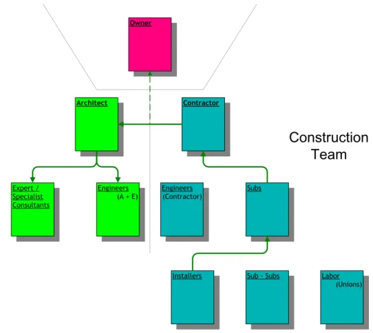
Figure II-1 Standard contractual organization ... 38
Figure II-2: Communication path and controls... 40
Figure III-1: Elements of 3D master model (DCH)... 53
Figure III-2: Structural wireframe contract model (EMP). Photo: L. Tighe, G. Metzger ... 54
Figure III-3: Coordination model of ceiling space ... 57
Figure III-4: CIFE’s 4D modeling tool (DCH) ... 58
Figure III-5: Finite element analysis of frame (Riscal) ... 59
Figure III-6: CFD fire safety analysis (Weatherhead) ... 60
Figure III-7: CFD wind studies (MIT)... 62
Figure III-8: Solar shadow studies (MIT)... 62
Figure III-9: Drawing extraction from the CATIA master model (MOT)... 66
Figure III-10: Re-integration of two dimensional information in 3D (MIT) ... 67
Figure III-11: Digitized data, CAD model and prototyped model. (Ohr). Photo: W. Preston.. 70
Figure III-12: CAT scan and reconstruction of a complicated physical model (DCH)... 73
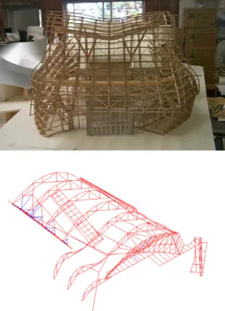
Figure III-13: The physical master model and its digital counterpart (MIT)Photo:W.Preston 74 Figure III-14: Schematic design phase physical and digital structural studies... 75
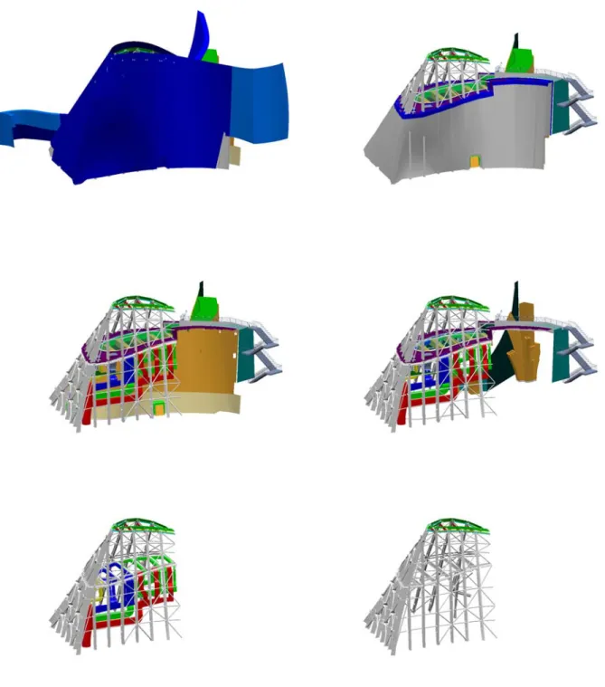
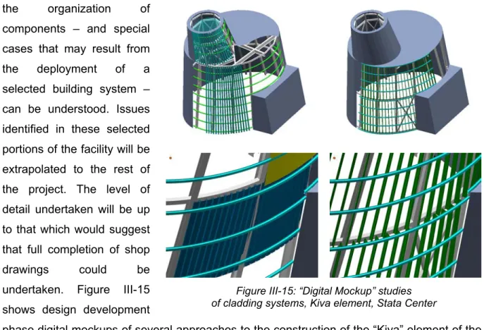
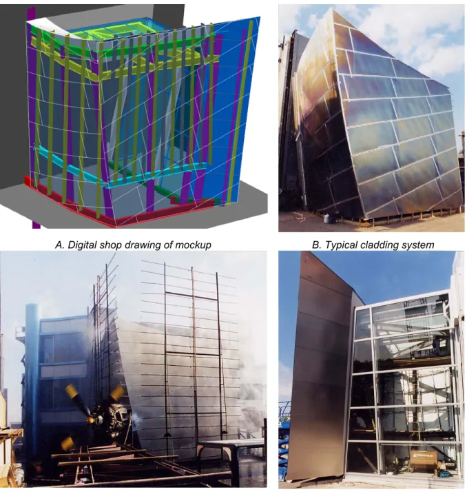
Figure III-15: “Digital Mockup” studies ... 76
Figure III-16: Performance mockup of DCH cladding systems. Photo: H. Baumgartner ... 77
Figure III-17: Physical model rationalized by digital modeling. Photo: W. Preston... 79
Figure III-18: Segmented construction of planar curves (DCH). Photo: W. Preston... 82
Figure III-19: Arc segment generated primary structure (MIT). Photo: H. Brawner ... 82
Figure III-20: Curved, planar pipe system (Weatherhead ) . Photo: G. Meyer ... 83
Figure III-21: Rationalization methods for planar curves ... 84
Figure III-22: Comparison of DCH and EMP structural schemes. Photo: Gehry Staff... 86
Figure III-23: Connection geometry on DCH. Photo: Gehry Staff... 87
Figure III-24: Steps in the CNC fabrication of EMP structural ribs... 88
Figure III-25: Two dramatically different fabrication systems for curved glass forms. Photo:David Heald... 89
Figure III-26: Curved surface glazed roof (Berlin Zoo, Schlaich Bergermann & Partner)... 92
Figure III-27: Construction of the translation surface... 93
Figure III-29: Attributes on enclosure system model (MIT), structural frame model (DCH)... 96
Figure IV-1: Examples of planar forms on Gehry project .Photo: Gehry Archives... 104
Figure IV-2: Horse’s head (DG Bank) .Photo: Gehry Staff ... 107
Figure IV-3 Horse’s head (Gagosian gallery) .Photo: Douglas M. Parker ... 107
Figure IV-4: CNC fabrication of cast concrete (Dusseldorf). Photo: Gehry Staff ... 108
Figure IV-5: Geometries based on fabric materials. Photo:Josh White ... 109
Figure IV-6: Paper surface constructions – physical models. Photo:W. Preston... 110
Figure IV-7: A wide range of “paper surface” materials and assemblies. Photos:A-C Gehry Staff, D. Erika Barahona Ede ... 113
Figure IV-8: Rationalization of a sphere ... 115
Figure IV-9: Macro and element scale sheet forms (Bilbao). Photo:Gehry Staff ... 116
Figure V-1: A line as a function on end points... 119
Figure V-2: Euclidean space basis vectors ... 122
Figure V-3: Description of a point in an affine vector space ... 123
Figure V-4: A vector field in R3... 124
Figure V-5: Expansion of a vector by orthonormal basis vectors. ... 125
Figure V-6: A manifold, defined as a mapping between parametric and containing spaces 128 Figure V-7: A space curve as three mapping functions... 130
Figure V-8: Mapping of a curve to a unit arc length parameterization... 133
Figure V-9: Osculating plane of a curve ... 133
Figure V-10: Normal plane of a curve... 134
Figure V-11: Curvature of a curve ... 135
Figure V-12: The Frenet frame vectors ... 135
Figure V-13: Torsion of a space curve ... 136
Figure V-14: The vectors t, n, and b as a vector field ... 137
Figure V-15: Parametric definition of a surface ... 138
Figure V-16: The partial derivatives of the surface function ... 139
Figure V-17: Tangent plane defined by the differentiating the surface function ... 140
Figure V-18: Isoparametric curves on surface... 142
Figure V-19: The family of surface curves through a point... 143
Figure V-20: The angle between surface and curve normals ... 145
Figure V-21: Decomposition of surface curve into normal and geodesic components... 145
Figure V-22: The normal curves at a point ... 147
Figure V-24: Positive gaussian curvature - “dome” configuration... 150
Figure V-25: Negative gaussian curvature configuration... 150
Figure V-26: Gaussian curvature as a relationship among principal curvatures ... 151
Figure V-27 Equivalent gaussian curvature family ... 152
Figure V-28: A family of polynomial curves ... 154
Figure VI-1: Gaussian curvature samples and curve ... 160
Figure VI-2: Acceptable and unacceptable curvature configurations ... 160
Figure VI-3: Control of gaussian curvature by introduction of tangency discontinuities ... 161
Figure VI-4: EMP site model. Photo:Josh White... 162
Figure VI-5: Terrazzo mockup (EMP). Photo:Gehry Staff ... 163
Figure VI-6: EMP design prior to selection of cladded surface system. Photo:Gehry Staff. 164 Figure VI-7: EMP design after rationalization for cladded surface construction Photo:Gehry Staff ... 164
Figure VI-8: Surface geometry conditions and associated test results (EMP)... 166
Figure VI-9: Gaussian curvature rationalization (EMP) ... 167
Figure VI-10: AZCO’s panel system ... 168
Figure VI-11: Developable surface as the limit of a family of planes ... 170
Figure VI-12: Parallel normal vectors on a developable surface ... 171
Figure VI-13: Basic ruled surface definition... 173
Figure VI-14: Ruled surface as a vector field ... 173
Figure VI-15: General developable surface condition on parametric surfaces ... 175
Figure VI-16: Space curve and Frenet field surfaces ... 176
Figure VI-17: Canonical developable surface forms... 178
Figure VI-18: Developable surface and its decomposition into developable regions ... 179
Figure VI-19: A tangent developable surface of two sheets. ... 179
Figure VI-20: Ruled surface defined by edge curves... 180
Figure VI-21: Input edge curves resulting in an infeasible developable surface condition .. 181
Figure VI-22: Paper sheet and developable regions ... 182
Figure VI-23: Developable surface approach based on (1,2) weighted Bézier patches... 185
Figure VI-24: Results of the developable surface application ... 186
Figure VI-25: Weatherhead project design model. Photo:W. Preston... 187
Figure VI-26: Digital developable surface modeling (Weatherhead) ... 189
Figure VI-27 Curved surface concrete formwork. Photo:G. Mayer... 190
Figure VI-29: Ladder truss system. Photo:G. Mayer ... 191
Figure VI-30: Back pan on hat channels. Photo:G. Mayer ... 192
Figure VI-31: Finish surface layers. Photo:G. Mayer... 192
Figure VI-32: Shingled developable form. Photo:G. Mayer ... 192
Figure VI-33: Conic form rationalization through traditional documentation (Weissman). . Photo:Gehry Archives, Don F. Wong ... 196
Figure VI-34: Conic form rationalization through digital documentation (DCH). . Photo: W. Preston ... 197
Figure VI-35: Gaussian curvature mapping on Bilbao project ... 198
Figure VI-36: Rationalization comparison. Photo:G. Mayer, G. Metzger... 200
Figure VII-1: Deformable body mapping function ... 209
Figure VII-2: A simple mass-spring model of sheet materials ... 212
Figure VII-3: Deformation modes of the idealized spring assembly ... 213
Figure VII-4: Results of materials simulation based on a simple spring model ... 216
Figure VII-5: Sheet configuration and internal strain map ... 227
Figure VII-6: Spring assembly with variations of spring force coefficient... 231
Figure VII-7: Varying the gravitational constant... 231
Figure VII-8: Variation of attractor force coefficient ... 232
Figure VII-9: Matrix organization ... 234
Figure VII-10: Sparsity pattern of a simple-mass spring system ... 237
Figure VII-11: Paper simulator interface... 239
Figure VII-12: Sheet views ... 240
Figure VII-13: Sheet modifications ... 242
Figure VII-14: Remeshing... 243
Figure VII-15: Mesh operations ... 244
Figure VII-16: Variation of simulation parameters ... 246
Figure VII-17: Elements of the simulation algorithm ... 247
Figure VII-18: Isometries of parametric mapping on Bézier surfaces... 251
Figure VII-19: Isometries of developable surfaces ... 252
Figure VII-20: Isometries of the materials based formulation ... 253
Figure VII-21: Translation between developable and material representations... 255
Figure VII-22: Original developable surface scheme (Guggenheim mesh installation) ... 257
Figure VII-23: Initial design proposal based on materials simulation... 259
Figure VII-25: Recalibration of material properties based on initial installation results... 260
Figure VII-26: Materials simulation design iterations of mesh curtain installation ... 261
Figure VII-27: Final installation and simulation... 262
Figure VIII-1:Physical sketch model, showing two shape classes (Ohr Museum)... 267
Figure VIII-2: Point set versus shape grammar subtraction... 269
Figure VIII-3: Mapping of Euclidean space shape transformations ... 274
Figure VIII-4: Mapping of shape transformations ... 274
Figure VIII-5: Composition of a curve on surface as manifold... 275
Figure VIII-6: Surface metrics as a parametric space labelling field... 277
Figure VIII-7: Gaussian curvature mapping into parametric space... 278
Figure VIII-8: Mapping of surface differential properties to a vector field ... 279
Figure VIII-9: Graph grammar resulting i n the subdivision of triangles... 281
Figure VIII-10: A complex as adjacency graph... 282
Figure VIII-11: Mapping of shared boundaries ... 283
Figure IX-1: Subdivision grammar metrics (EMP) ... 287
Figure IX-2: Base Mughul grammar production rule... 288
Figure IX-3: Image subdivision using a histogram metric. Image: W. Hokoda, W.J. Mitchell ... 288
Figure IX-4: Subdivision grammar results ... 289
Figure IX-5: Rules of the subdivision grammar... 290
Figure IX-6: Basic parametric subdivision grammar... 291
Figure IX-7: Subdivision grammar applied to EMP design development models ... 291
Figure IX-8 Grammar for face sheet layout on panels... 292
Figure IX-9: Subdivision grammar applied on EMP contract documents ... 294
Figure IX-10: Pipe routing through interstitial space... 295
Figure IX-11: Panel framing... 295
Figure IX-12: Elements of the EMP surface fabrication grammar.Photo:Gehry Staff... 297
Figure IX-13: Structural rib system ... 298
Figure IX-14: Tube and pedestal layout ... 298
Figure IX-15: Panel and face sheet edges ... 299
Figure IX-16: Finish surface ... 299
Figure IX-17: Fabricators rules for panel placement ... 300
Figure IX-18: AZCO’s Automatically generated shop drawings... 301
Figure IX-20: A construction of rectangular sheets and springs... 306
Figure IX-21: Boundary and resulting mesh configurations... 307
Figure IX-22: Cut features and resolution in the triangulation ... 308
Figure IX-23: Dodge insertion... 310
Figure IX-24: Insert creation ... 311
Figure IX-25: Possible 2D feature shapes... 314
Figure IX-26: Matrix of feature behaviors and shapes... 315
Figure IX-27: Shapes defined through sheet features ... 316
Figure IX-28: Distance metric on sheet ... 317
Figure IX-29: Strain map ... 318
Figure IX-30:Gaussian curvature approximation on triangulated meshes... 319
Figure IX-31: Input shape to grammar, after initial convergence of the simulator ... 320
Figure IX-32: Generative Rationalization Scheme ... 322
Figure IX-33: Surface patterns of rectangular sheets. Photo:Gehry Staff ... 323
Figure IX-36: Rectangle subtraction operations ... 325
Figure IX-37: Rectangle Boolean operators ... 326
Figure IX-38: Mapping of the parametric space rectangle grammar ... 327
Figure IX-39: Basic rectangle split operation... 328
Figure IX-40: Basic rectangle split operation... 328
Figure IX-41: Feature generation response to design shape curvature ... 329
Figure IX-42: Curvature – angle relationship... 330
TABLE OF SYMBOLS
Topologies and manifolds
R ... the set of real numbers, the real number line, the real number topology Rn ... n – dimensional Euclidean space, a Cartesian product of n real numbers n, m, etc ... the ordinality or degree of a Cartesian product space (e.g. Rn)
I... the set of integers, the integer topology Z ... a set of discrete values, the discrete topology
α, β, φ, etc. ... a mapping function of the form Rn
→
Rm, e.g. curves and surfaces. N, M, etc ... a bounded region of space in Rn, Rm, etc.a, b, c, etc. ... a (typically scalar, real valued) variable
p, q, etc ... a vector or vector field
I, j, etc ... the index of a vector component (e.g. pI )
Curves and surfaces
t...a scalar parameter in the curve function α :t→ x
α’, α’’, etc, ... differentiation with respect to t
s... the unit arc length parameterization of a curve
, ,
α α& && etc ...differentiation with respect to s
u... a 2-dimensional position vector in R2 “parametric space” u, v...the scalar components of ui
x... a 3-dimensional position vector in R3 “world space” x, y, z ...the scalar components of xi
Physical modeling
m... particle mass
M... the 3n x 3n particle mass matrix
t...time
h... time step (∆t)
n... vertex count
x... the 3n vector of particle locations v... particle velocity
f... force on a particle xi... R3 location of particle i
x1, x2, x3,... the individual (x,y,z) coordinates
φ...the R2 → R3 material mapping function ω...the linear approximation of φ on a triangle
C ...the behavior function
E ...the system energy
REFERENCED PROJECTS AND ABBREVIATIONS
Santa Monica Place, Santa Monica, CA 1973-80
Gehry Residence, Santa Monica, California 1977-78; 1991-92 Winston Guest House, Wayzata, Minnesota 1983-87
Edgemar Development, Venice, California 1984-88 Chiat Day Building, Venice, CA 1985-91
Lewis Residence, Lyndhurst, Ohio, 1989-95 (unbuilt)
Team Disneyland Administration Building, Anaheim, California 1987- 96
DCH Walt Disney Concert Hall, Los Angeles, CA 1987-
Barcelona Vila Olimpica, Barcelona, Spain 1989-92
Weissman Frederick R. Weissman Art Museum, Minneapolis, Minnesota 1990-93
Bilbao Guggenheim Museum Bilbao, Bilbao, Spain 1991-97
Prague Nationale-Nederlanden Building, Prague, Czech Republic 1992-96
Dusseldorf Der Neue Zollhof, Dusseldorf, Germany 1994-99
EMP Experience Music Project, Seattle, Washington 1995-2000
Berlin DG Bank Building, Berlin, Germany 1995-2001
Weatherhead Peter B. Lewis Building, Weatherhead School of Management, Case Western
Reserve University Cleveland, Ohio 1997-
MIT Ray and Maria Stata Center, Cambridge, Massachusetts 1998-
OHR Ohr-O’Keefe Museum, Biloxi, Mississippi 1999-
FOREWORD
Over the past decade, Gehry’s firm has developed a unique and innovative approach to the process of delivering complex building projects. Computer based project information plays a vital and integral role in enabling this process. The concepts and strategies that have emerged though the development of the firm’s methodologies offer profound lessons for the design community, not simply in the ways that computing may be applied to architectural practice, but in the ways by which computing methods can change the process of building. It is with an eye to providing further insight into this important example of computing and practice that this thesis has been prepared.
This thesis offers a view into Gehry Partner’s computer aided design methodologies, based on the author’s experiences with the firm over the past half decade. Rather than attempting to tell this story in a historical or encyclopedic fashion, this thesis takes as its object of inquiry a specific set of building intentions, and associated computational strategies, playing a fundamental role in the firm’s work: the design, engineering and fabrication of surface forms
on Gehry’s projects. This set of issues is explored as a topic of substantial interest in its own right, while serving as an example of the larger sets of intentions exhibited by the firm’s practice.
The qualities of materials and the role of craftsmanship as guiding intentions of Gehry’s work have received considerable discussion41. These intentions have critical counterparts in
project documentation and construction activities, and in associated computational constructs. The goal of adequately representing intentions of materiality and craft in digital form is perhaps the most important and complex aspect of the firm’s computing efforts. These intentions are fundamental motivations of the firm’s approach to digital representation of the geometry of project forms, and of the fabrication processes responsible for their realization. These are central themes of this thesis.
This body of this text is organized into three parts. Part 1 offers an introduction to the role of computing in Gehry’s design and building delivery process. Computing is explored in its relationship to key project design, analysis and construction intentions. Important concepts guiding the development of the firm’s computing efforts are presented, including the nature of geometric representations employed by the firm, and the role of analytically driven operations
on project geometry. A set of materially guided intentions fundamental to the generation of Gehry’s surface forms are introduced. Examples and case studies are provided that demonstrate the application of these tenets on recent projects. This introductory section establishes the framework for the inquiry developed in the remainder of the text.
Part 2 focuses on developing a formal representation of materially guided surface forms. This section describes the firm’s efforts to develop digital counterparts to the behavior of surface materials in modeling and fabrication. A review of the theory of topology and manifolds underlying representations of curved spatial objects is presented in Chapter V, followed by a rigorous formal exploration of the geometric structures employed by the firm and their applications to specific constructibility problems. A promising new approach to the representation of surfaces through physical modeling of material behaviors is presented in detail in Chapter VII. This Part establishes a unified geometric framework for the modeling, simulation and analysis of the elementary shape elements employed in the firm’s designs.
Part 3 expands on this geometrical framework, in developing a formal methodology for considering assemblies of these basic surface elements. This extended framework has implications for the digital representation of project scale gestures, as well as utility for addressing localized surfacing system fabrication and assembly requirements. With a formal framework for the representation of surface organizations established, the discussion turns to operations on these assemblies. The potential is demonstrated for automaton of key processes addressing constructibility requirements of building systems. Several examples of these generative approaches to the design of surface systems are documented. The thesis concludes by presenting a computational framework for the generation of materially guided surface assemblies.
I. INTRODUCTION
It seems that Gehry’s practice has become synonymous with cutting edge computing technology and CAD / CAM manufacturing processes. But the path to the firm’s prominence in architectural computing applications has not been easy or straight forward. Gehry himself remains skeptical of computing as a tool for design96. He speaks with a certain degree of pride in his inability to operate a computer, and suggests that the quality of the digital image is dangerous and subversive to the designer’s eye.
Gehry’s design process is perhaps best characterized by its emphasis on physical objects as the principal artifacts on which design takes place. The firm places a unique emphasis on the development of designs through physical models, full scale mockups and other physical artifacts as the means for understanding and developing design intentions. These artifacts of include numerous sketch models, some undergoing active transformation while others wait on shelves or in storage, documented in photos, serving as records of design intentions at significant points in the process. These models are often deliberately developed to a rough, unfinished state, in order to allow suggestion of new directions of development as the designers contemplate the objects. The power of this design process springs in part from the ambiguity presented by this multiplicity of physical design representations.
These evocative qualities of the firm’s designs persist in the further development of projects as they enter documentation and construction phases. Project engineering and detailing strategies are often developed that accommodate the real world indeterminacy of on-site construction events. Many building system strategies have involved in-situ fabrication and placement of system elements as a means for responding to on-site conditions. This reliance on the efforts of craftsmen, operating in the field, again reflects the profound concern for physical artifacts and events as driving elements of the design process and the aesthetic that results.
The role of computer-based methodologies in this fundamentally tactile, evocative process presents a dilemma. Contemporary CAD modeling capabilities seem to stand in marked contrast to these design intentions. CAD modeling strips away ambiguity, producing definitive geometric forms that “leave little to the imagination”. These digital, logically founded
constructs stand in curious contrast to the indeterminacy of physical based activities and artifacts.
The physical / digital interactions, and the tension between these realms of the process have become fundamental to the success of the firm’s design process. At the heart of the process is an ongoing affinity between a disparate set of design intentions, embodied in multiple physical representations, and a coherent set of computer based representations. The process utilizes the definitiveness computer representations at points in the process where it is appropriate, and draws these digital descriptions into the assemblage of representations. The computer based description represents the glue that ties the physical design representations together, and ultimately document their convergence. Computer representations allow the intentions embodied in multiple physical representations to be resolved, translations of scale to be performed, and incursion of system fabrication decisions to be resolved into the design intent.
Three dimensional computer aided design applications provide a critical characteristic relative to traditional building documentation, in the ability to translate design intentions from physical design artifacts to constructed objects without recourse to two-dimensional representations. On more “conventional” building projects, this direct translation is unnecessary and perhaps inefficient. Conventional two dimensional architectural documents, comprised of plans, sections, elevations and details, compress the full spatial and dimensional scope of a design into a set of inter-related representations. The regularity of an object whose dimensions may vary little or not at all from floor to floor can be efficiently described by a single floor plan background, repeated for each floor. Variations in fit out can be overlaid on this normalizing representation. Typical details may be specified as a single detailed drawing. Its application across the project is specified by annotation on floor plans or sections, or in specifications. For buildings with repetitive components, and regular floor plans, the necessity for individually describing each element as a three dimensional model correctly positioned in space would require substantial additional labor. The ability to mentally resolve multiple two-dimensional representations of a design into a coherent understanding of the three dimensional object and its methods of construction is a core part of traditional architectural training and heritage. Architects take a professional pride in the development of this mental ability.
The relationships between tools, process of making enabled by tools, and the objects produced by operating tools are subtle and deep. The operations enabled by a chosen tool guide the operator to make specific types of objects or products that the tool affords. The parallel rule and triangle, blue print and tracing paper overlay of conventional document production facilitated the design of orthogonally organized building designs. The compass allows circular arcs to be included in these compositions. When two-dimensional plans are extruded perpendicularly to the plane of the paper in a uniform fashion, a single drawing presents a slice through the designed objects whose applicability is invariant of where the cut is taken. The two dimensional drawing construction provides tremendous expressive power in describing this geometric regularity. In turn, the designer is subtly guided toward the development of designs for which the utility of this geometric construct holds. More elaborate geometries than simple extruded form are of course possible, by combining multiple sections either in parallel or orthogonally, but the “trace” of the tool is inevitably felt in the resulting designs.
The adoption of the tools of two-dimensional representation has provided a basis for the development of descriptive conventions unifying the building industries. This shared language has Euclidean geometric forms and their sectional representations as an underlying construct. Straight lines stand in for wall and floor planes, arcs represent cylindrical forms. Parallel bold lines represent vertical walls, dashed lines represent overhead elements, usually aligned with elements on a floor plan cut at a higher elevation. This common understanding among participants in a building project is so deeply shared that it eludes dissection. An architect and contactor can discuss the layout and construction of a building on the basis of a two dimensional floor plan without any discussion of what the elements in the drawing mean. In parallel with the development of this common language of Euclidean elements, numerous interwoven industries and industrial processes have been developed around the making of Euclidean objects and building components. Saw mills turn trees into straight lumber of square profile and flat, rectangular sheets of plywood, steel mills extrude molten steel into linear members with invariant profiles. Carpenters use plumb bobs, string, levels and 3:4:5 triangle measurements to produce straight, vertical walls and their perpendiculars. So pervasive has the “tyranny” of Euclidean geometry become in the building industries that any building designed without strict accordance to its rules is subject to characterization as impossible to build.
In Gehry’s design process, physical model making is the principal design tool. This primacy of the construction of physical objects as the vehicle for design explorations in itself propels the firm’s work beyond the constraints of the Euclidean rationale. In its place, a new set of guiding rules have been developed, directly related to the materials and operations available to the processes of object making. Viewed in isolation, the operations of physical modeling are insufficient to guarantee the constructibility of the full scale products that models are intended to represent. However, in Gehry’s process, models serve not simply to describe the object in scale. Rather, the processes and materials of model making are brought into alignment with, and stand in for, those of craftsmen and fabricators on the resulting building construction. Materials and construction strategies are selected to emulate aspects of their full scale counterparts. This approach binds the operations of design directly to those of building, bypassing the filter of a common language of Euclidean geometry.
Prior to the firm’s adoption of computing based practices, the firm’s process suffered a key limitation in its methods of project documentation. While the firm could reasonably guarantee that the designs could be fabricated, the designs still required rendition into conventional two-dimensional description to support steps of the conventional construction process, including building permit submissions, bidding and on-site project layout. In order to bring the design back into the language of building industry convention, two dimensional plans, sections and elevations needed to be developed. Often, the forms of the models would require re-interpretation into conventional Euclidean forms of planes, cylinders and cones, simply to be consistently described through plans and sections.
Even with this painstaking development of project documentation, the geometry was still beyond the norms of conventional construction description. While fabricators could build the shapes, the process of bidding and coordinating the projects presented difficulty to construction managers. Accuracy of quantity takeoffs could not be guaranteed using conventional methods of measuring off of plans. Shop drawings – necessary for describing the detailed fabrication geometry – were difficult to render into orthogonal views. Spatial coordination of building elements became unmanageable as component details were developed. The limitations of understanding the project geometry through the lens of two dimensional views exacerbated perceptions of project complexity.
The history of the development of computer assisted building delivery by the firm in response to these limitations has been well documented52. Jim Glymph joined Gehry’s firm in 1989.
Glymph had substantial experience in the role of Executive Architect on several substantially complex building projects, including the San Diego and Los Angeles Convention Centers. At the time, 3D CAD was beginning to have application to architectural visualization, movie animation and automotive and aerospace design. Glymph realized that these technologies could be applied to the processes of architectural documentation, independent of the contemporary interest in the technology as a means for project visualization.
Initial forays into the technology were tentatively undertaken. The firm selected the Barcelona Fish sculpture – part of the Vila Olimpica project as an initial test of the approach. The fish sculpture – a 50 meter long sculpture of woven stainless steel mesh on a structural steel frame – provided a relatively safe test case for the use of digital representation as a vehicle for construction documentation. As a sculpture, with minimal life safety or building system issues, only the geometry of the project and the elements of fabrication needed to be represented digitally. Code compliance documentation requirements were minimal compared to that required for an inhabitable structure.
The development of the surface mesh geometry presented substantial concern for the design team. The mesh was understood to have a resistance to forming in an arbitrarily curved
fashion, and would buckle undesirably if certain constraints on the surface form were adhered to. Additionally, templates for cutting the shape of the mesh elements needed to be provided.
Figure I-1: Barcelona fish, physical and digital construction models.
Glymph contacted William J. Mitchell, then Professor of Architecture at the Harvard Graduate School of Design, who produced an initial model of the design in the Alias software package with graduate student Evan Smythe. While the results of the study demonstrated the possibility of representing construction documentation in digital form, a critical limitation emerged in the Alias software’s underlying representation of surfaces. Alias represented the surface of the sculpture through a tessellation of triangular faces. While this representation was sufficient to provide visual fidelity to Gehry’s initial physical model, geometric operations on the surface required to produce the structural steel model were problematic. The sculpture’s skeleton is constructed as a set of planar, vaulted truss “ribs”, offset from the surface, and connected to a cross braced structural steel skeleton. Intersections of the rib planes with the tessellated surface resulted in segmented polylines. It was difficult to control the segmentation of the mesh surface produced by Alias to correctly produce the required segmentation of the steel trusses. Offsetting of curves to produce the bottom chord of the trusses and other geometric operations produced similar undesirable linearization of the geometry.
Realizing that this segmentation of smooth surfaces would be a critical limitation to its digital construction documentation process, the firm began to search for more advanced representational capabilities in other software packages. At the time, the CATIA software package was one of the few CAD platforms offering true smooth surface representations. CATIA – initially developed by Dassault Aviation as an in house CAD application for the development of the Mirage fighter plane – had recently been released as a commercial application through IBM and was gaining acceptance by the automotive and aerospace industries. At the time CATIA Version 3 had achieved a commercially viable CAD application based on Bézier curve and surface algorithms28.
As an engineering tool, CATIA also offered capabilities for surface analysis not provided by Alias. While unable to provide a detailed assessment of the mesh behavior, capabilities for analyzing surface curvature were supported. Additionally, CATIA allowed curved surfaces to be flattened into shapes allowing a reasonable approximation of the mesh profiles required to cover the surface. These utilities, while representing quite loose approximations of the true mesh behavior, were sufficiently powerful to support the design and detailing of the mesh surface.
Rick Smith – proprietor of the consulting company C-Cubed - was at the time an independent IBM business partner, providing CATIA services to the southern California aerospace industries. Smith revisited the digital modeling of the fish, demonstrating the possibility of accurately creating the curved geometry of the surface and the construction of the structural steel geometry as offsets and intersections derived from the curved surface model. Construction of the sculpture was awarded to Permasteelisa, an Italian curtain wall fabrication company, for what would be the first of many successful collaborations between the two firms. Smith brought his model and CATIA station to Italy and worked directly with the Permasteelisa’s engineers and fabricators to produce the shop drawings for the steel and layouts for the mesh elements.
Glymph characterizes the experiences of the Barcelona Fish project as a breakthrough in many ways. The fact that the project, with its admitted geometric complexity, was completed on time and on budget, while the conventional steel construction of the rest of the Pavilion complex was suffering construction delays and on site reworking of steel elements “showed that [the firm] was onto something” in identifying a new process for project documentation. Furthermore, the direct collaboration with Permasteelisa on the development of shop drawings - with the endorsement of the project owner - circumvented the conventional disassociation between architect and fabricator.
At the same time as initial experiments in digital project description were being conducted by the firm, Dassault Systèmes, the developers of CATIA, were developing a comprehensive methodology to support the design of Boeing’s 777 aircraft line. Dassault termed this methodology Digital Mockup (DMU), with the intent to support design, detailing and CNC fabrication of the 777 aircraft and all components in an integrated, paperless fashion. This development effort resulted in software functionality within the CATIA product line beyond the limited functionality of curved surface description that Gehry’s firm had initially sought. The story of these developments in the digital design of manufactured products presents a parallel history to Gehry Partners’ efforts in developing similar methodologies for the support of building projects, and served as an important example closely observed by the firm. The parallel development of these manufacturing methodologies has also disclosed important differences in economies and supply chain organization between “vertically integrated” industries such as the aerospace industry, with opportunities afforded by economies of scale,
and the constraints of process imposed by construction industry. Comparisons between the methodologies of these industries are discussed below.
Applications to building projects followed shortly. The Nationale-Nederland Building in Prague and Team Disneyland Building drew on elements of the process proven on the Barcelona Fish. The development of the firm’s process culminated with the opening of the Guggenheim Bilbao museum in 1997. While refinements of the process continue, the essential elements of the process and its applications were defined in the early successes of these projects.
It would seem, from the success of these projects, that digital representation is poised to free architecture from the constraints imposed by historically developed project description. Complexity of geometric representation and methods of constructibility are apparent in the design and construction of Gehry’s projects, but digital technology seems to have proven up to the task of resolving this complexity. Digital modeling now allows free form, non-Euclidean shapes to be represented with exacting tolerances. Digital CNC fabrication technologies, developed to serve the automotive, aerospace, and Hollywood animation industries stand ready for application to building, faithfully rendering building components to similar exactness. The Boeing 777 project and other manufacturing processes have proven the viability of a fully digital design development process. To the delight of some critics and the dismay of others, digital technology seems poised to cast off the last relics of a historically developed building context, translating the designer’s gesture effortlessly into final form through Hollywood animation software coupled to robotic production devices. As post modern historicism freed design from contextual constraints, digital representation seems poised to remove the remaining constraints imposed by historically developed conventions of building description and production.
It would be unfortunate to draw so simple a lesson from Gehry’s work. The firm’s ability to successfully realize innovative forms springs partly from its ability to bring these projects
within the context of conventional construction documentation and building process. A view of the development of Gehry’s body of work shows a formal language that originates in the forms and materials of conventional construction, and an ongoing experimentation to press these materials and methods to their limits. The succession of Gehry’s built projects shows a gradual, continual coaxing of the conventions of fabrication and building, each work drawing
on the lessons learned from previous successes to push building method in new directions and to further limits. The power of Gehry’s architecture springs partly from a struggle, negotiation and ultimate reconciliation with existing context and conventions.
Part of the role of digital technology in the firm’s process has been to disclose simplicity within the geometric complexity, and to bring the description of building elements and processes within the conventional language of contemporary construction practice. This discipline is key to the success the firm has enjoyed in successfully completing projects. Perhaps surprisingly, much of the detailing of building components relies on extensions to conventional processes of building, and seldom relies on aerospace or Hollywood methods of object making. Rather, the firm strives to work with the existing processes of craftsmen and fabricators, and attempts to produce detailing and documentation strategies that reflect a deep understanding of the methods and constraints of existing fabrication processes. Two dimensional documentation, flat patterns, Euclidean cut edges and profiles are the norm in these fabrication methods. Digital technology is drawn on to render Gehry’s forms within these conventions; is it not seen as an opportunity to discard the capabilities of traditional craftsmanship. Part of the reason for this approach is of course necessity. Even where fully digital fabrication technologies are available, the costs of these methods are frequently prohibitive. But part of this methodology seems to be drawn from Gehry’s embracing of material qualities and craftsmanship, and an aesthetic that pushes conventions to their limits, rather than creating a design language from scratch.
Viewed from a geometric perspective, the methods drawn on in the digital description and documentation of projects are enabled by capabilities for developing project descriptions in full three dimensional, digital form, using non-Euclidean geometric constructs. However, the reliance on non-Euclidean geometric constructs in no way means that these structures are constraint free. Non-Euclidean, digital representations bring their own constraints and artifacts to description processes, in the forms that can be represented, the geometric operations that can be performed, and the fabrication processes that are enabled. This structuring of non-Euclidean geometry on surface representation and associated constructibility will be a central theme of this thesis. It will be shown that the non-Euclidean representational constructs at the heart of the firm’s digital process can in fact be positioned as extensions of Euclidean constructs into a more general framework, in which Euclidean and a variety of non-Euclidean descriptive elements coexist on equal footing.
II. THE DEVELOPMENT OF GEHRY’S BUILDING PROCESS
In order to realize the innovations of Gehry’s forms on built projects, corresponding innovations of design development and building process have been required. The firm’s computational innovations have been developed parallel to, and as part of, these building process innovations. To understand the context in which the firm’s digital process has evolved, it is appropriate to review some of the guiding intentions of the firm’s building delivery methodologies that these digital representations serve.
A.
PROJECT COST CONTROL
It may not be overstatement to say that project budget control – and the reconciliation of design intent with project financial requirements – are the most important driving forces behind the firm’s design development phase decisions. Certainly, project cost control has been the most important factor in the development of the firm’s digital building delivery process. This position may surprise readers. It is sometimes assumed that Gehry’s practice engages predominately or exclusively in “budget less” projects, with clients for whom money is no object. This is far from the truth. The firm has achieved its successful track record of completed projects by providing buildings within clients’ budgets, and within the rough per square foot costs of more conventional projects of similar building usage types.
Project costs can be broken down in a number of different ways. First, the distinction is often made between the “soft costs” of a project, including the design services of architects and engineers, versus the ‘hard” costs attributed to actual construction materials and labor. Second, there is an important distinction to be made between costs identified prior to commencement of construction, roughly up the GMP (Guaranteed Maximum Price) bid phase, and cost overruns that can crop up during construction. Both of these distinctions are subject to further inspection in light of the new forms and processes championed by Gehry’s firm.
It is often assumed by owners that the hard costs of a building are a fixed factor in building construction, while soft costs are an area for flexibility. This reasoning seems at a preliminary glance to be valid. In theory, a 2x4 stud is a 2x4, a cubic foot of concrete is a known quantity. The unit prices of these materials seem relatively fixed. Buildings of a certain size require
certain amounts of material. Metrics for these material quantities relative to square footages of given construction types are available in the industry. Quantity estimating on conventional construction is a fairly straight forward process. The estimator adds up linear wall lengths from the 2D drawings, multiplies this length by the height of the walls to determine square footages, throws in a percentage for material waste, and multiplies these quantities by established local costs for the building materials and per quantity estimates of hours and rates of construction labor, to arrive at a cost for the construction of a given building system. If the client is interested in higher quality materials or construction, these decisions can increase the cost of construction, but in theory the client “gets what he or she asks for” in terms of a higher quality product. In turn, it is perceived that the soft costs of the architectural and engineering services have some flexibility. If the architect spends less time in schematic design, the number of billed hours can be reduced, beneficially impacting the bottom line of the building construction budget. On many conventional building projects, the design services are seen as an area to squeeze some cost reduction.
The above distinctions between soft and hard costs of construction may be valid for conventional construction, where quantities and associated costs are relatively well established. On unconventional construction, where established industry costs for the type of construction are not available, the rules of the game are thrown wide open. Even the straight forward activity of quantity estimating can be difficult to accurately perform if these quantities can not be easily determined from conventional 2D documentation. Material waste factors can be difficult to estimate, since atypically shaped building elements can be more difficult to fit on industry standard sheets of material. The labor associated with unit quantities of unconventional construction systems can be difficult to anticipate.
Even on conventional construction, construction budgeting is less of a science than it first appears. For conventional construction, rough per unit cost rules of thumb are available in the industry, and are known to architects and construction managers. These unit costs vary widely from region to region, and are substantially impacted by short term localized economic factors. Factors contributing to the cost of a given system include local availability of materials and equipment, availability of skilled vs. unskilled labor and the influence of trade unions, and competition among projects in a given locale for certain elements of construction. A “hot” building market will drive up costs for most basic construction systems, as demand for sub-contractors is driven up. The history of Gehry’s projects is rife with
anecdotes of these local and temporary economic considerations. The economic feasibility of titanium for the Guggenheim Bilbao project is traced to a temporary glut of available titanium in the world market after the fall of the Soviet Union. The Big Dig project in Boston reduced the available concrete contractors in the local market during the construction of the Stata Center. Low demand for skilled carpenters in the Czech Republic after the fall of communism contributed to the development of a hybrid digital / manual fabrication process for concrete panels of the Nationale – Nederland project.
The premium on direct hard costs associated with unconventional project geometry is an important factor in preliminary project budgeting. This premium is acknowledged by clients as a cost associated with the acquiring one of the firm’s designs. The rationale of cost associated with receiving a superior product is applicable to Gehry’s buildings. Many budgetary tradeoffs are made throughout schematic design phase decision making. For example, Gehry’s design aesthetic suggests more economical, conventional materials used in unconventional forms, in lieu of more expensive finishes applied to conventional geometry. Mixing project geometry to include conventional construction and geometry along with more highly shaped elements is an important element of the design process. These tradeoffs can be managed in schematic design in order to meet client budget requirements.
A more problematic aspect of project budgeting can be identified, in terms of risk
management. In North America, construction sub contracts are typically awarded based on guaranteed price bids. Typically, construction sub contracts are awarded through a competitive bidding process, with the low bidder being awarded the contract. The recipient of the contract is obligated to perform the agreed upon services – specified through project documentation - for a contractually committed price. On conventional construction, sub contract estimators have a good understanding of their internal unit price costs for conducting work, and can make trade offs between competitive pricing and profit margin. On unconventional construction, where prior experience and industry established price points do not exist, cost estimation is difficult to conduct with any guarantee of successful completion of the project. The level of risk associated with contracting to perform the work at any specific price can be substantial. The result can be sub contractor bids containing large factors of safety, which ultimately represent premiums on the price of construction. Many sub contractors will simply elect not to consider taking on the work, reducing the competitive pool of providers and resulting in higher cost bids being accepted. The premiums cannot be
construed to be costs associated with a superior product, but simply represent higher costs for the same quality of construction. This price of risk can dwarf the premiums that can be expected due purely to additional labor or materials.
While the pre-construction pricing exercises can jeopardize the commencement of a project, lack of project and associated cost control during construction present even greater jeopardy to the project and participating organizations. The major risks in terms of cost overruns during construction can be traced to lack of dimensional coordination, and errors and omissions in construction documentation or their interpretation. Errors in dimensional coordination can result from mis-communication between trades, misunderstanding of dimensions of components, and complexities of routing equipment through tight spaces, such as duct runs of mechanical systems. Obvious errors of miscalculating dimensions on traditional 2D documents or not updating dimensions on plans when updates and changes are made occur all to frequently on conventionally documented construction drawings. When such errors escape notice until they are discovered in the field, at best re-work is necessary. More significantly, this rework can cause delays impacting many of the trades on the job. If these delays are significant enough, they can cause a “ripple affect” where subsequent trades are impacted. For example, the mis-sizing of a single primary steel beam, discovered in the field can delay the placement of adjoining members while the erroneous member is rebuilt and shipped. In turn, placement of any system to be attached to the primary steel system may be held up. If delays are significant, they can put in jeopardy guaranteed contracts with sub contractors, who may have other work scheduled in anticipation of completing their portion of the job by a certain date. The costs of running a large construction site per day can be substantial even without the subcontractor labor costs.
Improved project information provided by 3D CAD documentation has the potential to address many of these issues, allowing control of, and dramatically reducing, the so called “hard costs” of project construction. Much of the cost saving opportunities offered by information technology can be traced to reduction of risk. By facilitating improved unit quantity estimates early in schematic design, budget tradeoffs can be played out before detailed design has begun. Improved dimensional coordination can be a direct outcome of “virtually” constructing the building and its components to some level of detail prior to generating contract documents. Tricky or idiosyncratic conditions for typical system details – at corners or atypical interfaces with other systems – can be identified prior to committing
work contractually. Admittedly, this added information may give prospective bidders better insight into the complexity of the project, resulting in higher initial bids. However, if this complexity were to be discovered after the fact, disputes about the completeness of construction documents would need to be resolved, likely resulting in remediation.
Part of the successful design development practices of Gehry’s firm results from the frequent use of conventional system detailing, applied to unconventional geometry. The firm is continually cognizant of the availability of locally available talented craftsmanship, and seeks to take advantage of the materials and practices of their local construction practices. This is part of the contextual aesthetic of Gehry’s designs, and an aspect of the respect of craftsmanship for which the firm is known. One strategy for reducing project costs is to be able to provide construction information in a format familiar to these local trades. The 3 dimensional project database allows information to be “sliced and diced” to extract information supporting construction practices familiar to these local trades. If the description of complex geometry can be provided in a format that supports practices familiar to these trades, the risk factor can be reduced or eliminated. Complex geometry may still carry a premium in labor and material, but these factors can be understood in terms of real impact on the costs of construction, not buried in excessive cost contingencies to protect the contractor from unknown risks.
B.
BUILDING TEAM ORGANIZATION AND INFORMATION FLOW
The conventions of contractual relationships among organizations participating in a construction project vary widely in different parts of the world. In many ways, the North American construction environment is among the most difficult for supporting unconventional building practices. It is partly for this reason that many of the early successes of the firm’s digital building delivery process were achieved on projects outside North America. Much of the development of the divisions between design and construction teams can be traced to the increase in construction litigation that has occurred in America since the 1950s. To protect the various partners from litigation, strict boundaries have been defined for the scope of responsibility each party takes on, and the flow of information between parties.
Contractor Owner Architect Subs Expert / Specialist Consultants Engineers (A + E) Engineers(Contractor) Sub - Subs Material
Suppliers Installers Labor (Unions)
Product Suppliers Design Review Agencies Independent Q. C. Testing / Inspection
Design
Team
Construction
Team
Figure II-1 Standard contractual organization
Figure II-1 diagrams the contractual relationship between organizations on a standard North American design – bid - build project. The contractual relationships are organized as a tree. The major contractual relationships are defined between the owner and architect, and owner and contractor. The architect is “prime contractor” for the design team, which specifies the scope of construction through construction drawings and specifications. The general contractor is responsible for the construction of the project per the construction documentation provided by the design team. All contractual relationships at the top of the hierarchy are with the owner; no contractual relationship exists between the architect and general contractor.
The architect sub-contracts for engineering services to structural, mechanical, acoustical, lighting and other consulting engineers. Various specialist engineers may be enlisted to perform peer review on the work of the engineering team. The design team completes the
specification of the project to demonstrate conformance with local building codes, and to sufficient level of detail to guarantee in theory that the project can be built without errors or conflicts between the activities of building trades.
The general contractor in turn apportions work, at their discretion, to internal resources or to subcontractors. These contracts need only to guarantee that the specifications of the design team are met; beyond these base line requirements the contractor is free to select any contracting organizations that can reasonably be expected to perform the work. The contractor will generally award sub contracts on the basis of lowest bid.
Sub contracting organizations “fill in the details” of the project specification through shop drawings that describe building systems and components to a level of detail necessary for actual construction. The sub contracting organizations have their own engineering teams that conduct detailed engineering of system components to verify that proposed fabrication meets the standards specified by the design team. Again in theory, the contract documents provided by the design team have anticipated all the geometric and coordination conditions that will occur as a consequence of the systems that have been selected for the project. In practice, the level of detail performed by the design team to define the resolution of typical conditions may not anticipate all the actual localized conditions generated by the specified systems. The level of detail provided by the shop drawing detailing may be necessary to disclose the full range of implications of a selected building system strategy. Any discrepancies between general and actual localized conditions can be a source of dispute between the design and construction teams. These shop drawings are submitted to the design team for review, comment or exception. The design team is usually responsible for guaranteeing that the details specified in the shop drawings can be dimensionally coordinated between trades. Note that dimensional conflicts between the work of different trades may not be apparent in any single trade’s shop drawing submissions. Coordination through integrating information contained on numerous shop drawings may be required for the design team’s review. Problems can be difficult to detect when this information is contained on disparate two dimensional documents.
When a condition is detected by the sub contractor that is beyond the scope of the details specified by the bid package, requests for information (RFIs) are generated by the sub contractor and sent through the contractual hierarchy to the architect - as head of the design
Contractor Owner Architect Subs Expert / Specialist Consultants Engineers (A + E) Engineers(Contractor) Sub - Subs Installers Labor (Unions)
Design
Team
Construction
Team
Figure II-2: Communication path and controls
team - for clarification of design intent. Depending on the severity of the condition, the design team may issue a supplemental information document (SI), indicating that the design team believes the condition is within the original intent of the contract documents. If the condition is determined to be outside the scope of the details specified in the contract documents, change orders may need to be generated. The generation of change orders indicate that resolution of the condition is in fact beyond the scope of the original construction documents and contract, and will frequently generate additional fees for the construction team. This change of contractual scope will necessarily require the approval of the owner.
Information flow between organizations is strictly controlled along the paths of contractual relationships (Figure II-2) . The parties higher up in the contractual tree are typically leery of allowing their sub contractor organizations to communicate or make decisions directly with other organizations, since they are ultimately responsible for the work of the subordinate organizations. Worse, the fear is, subcontracting organizations may “leak” information about internal decision making between contracting and sub contracting organizations to