Publisher’s version / Version de l'éditeur:
Vous avez des questions? Nous pouvons vous aider. Pour communiquer directement avec un auteur, consultez la première page de la revue dans laquelle son article a été publié afin de trouver ses coordonnées. Si vous n’arrivez pas à les repérer, communiquez avec nous à [email protected].
Questions? Contact the NRC Publications Archive team at
[email protected]. If you wish to email the authors directly, please see the first page of the publication for their contact information.
https://publications-cnrc.canada.ca/fra/droits
L’accès à ce site Web et l’utilisation de son contenu sont assujettis aux conditions présentées dans le site LISEZ CES CONDITIONS ATTENTIVEMENT AVANT D’UTILISER CE SITE WEB.
Research Paper (National Research Council of Canada. Division of Building
Research); no. DBR-RP-657, 1975-08
READ THESE TERMS AND CONDITIONS CAREFULLY BEFORE USING THIS WEBSITE. https://nrc-publications.canada.ca/eng/copyright
NRC Publications Archive Record / Notice des Archives des publications du CNRC :
https://nrc-publications.canada.ca/eng/view/object/?id=7af79dc8-430d-41b3-b8c6-4beb1a87f0bb https://publications-cnrc.canada.ca/fra/voir/objet/?id=7af79dc8-430d-41b3-b8c6-4beb1a87f0bb
NRC Publications Archive
Archives des publications du CNRC
This publication could be one of several versions: author’s original, accepted manuscript or the publisher’s version. / La version de cette publication peut être l’une des suivantes : la version prépublication de l’auteur, la version acceptée du manuscrit ou la version de l’éditeur.
For the publisher’s version, please access the DOI link below./ Pour consulter la version de l’éditeur, utilisez le lien DOI ci-dessous.
https://doi.org/10.4224/40001666
Access and use of this website and the material on it are subject to the Terms and Conditions set forth at
The scaling of fire resistance problems
S e r TH1
N21r2
no.
657
NATIONAL RESEARCH COUNCIL OF CANADAc . 2
CONSEIL NATIONAL D E RECHERCHES DU CANADA BLDG
The Scaling of
Fire Resistance Problems
by
J. H. McGuire, W. W. Stanzak and Margaret Law
Reprinted from FIRE TECHNOLOGY Vol. 11, No. 3, August 1975
p. 191-205
Research Paper No. 657 of the
Division of Building Research
SOMMAIRE
Les auteurs presentent les rapports de graduation de la con- duction thermique, en particulier quelques-uns qui font le lien entre temps et dimension, et se servent de resultats empiriques pour les appliquer aux problemes de la resistance au feu, y compris celle des poteaux d'acier enrobes de beton. En plus d'etre simple, cette methode de graduation n'exige pas une connaissance des proprietes thenniques des materiaux en question et elle tient compte de la variation des proprietes thermiques en fonction de la temperature ainsi que de plusieurs effets de l'humidite.
F I R E TECHNOLOGY
The Scaling
of
Fire Resistance Problems
J. H. McGUIRE,* W. W. STANZAKt and MARGARET LAWS
Heat conduction scaling relations are given, particularly some relating time and dimension, and empirical findings are used t o permit their extension to fire resistance problems, including those relating to concrete-encased steel columns. The merit of scaling, apart from its simplicity, is that i t does not require a knowledge of the thermal properties of the materials involved and that i t takes into account variation of thermal properties with temperature and many of the effects of moisture.
F
IRE RESISTANCE is a property of elements of a structure and is asso- ciated with the intention on the part of the designer to confine fire to its compartment of origin. The fire resistance of an element is usually defined as the time during which it will comply with various requirements when subjected to test by a furnace following some specified standard time- temperature curve. Load bearing elements, including columns and some walls and floors, will be required to sustain a specified load for the duration of the test. Quite distinct from this requirement are others relating to elements of structure, such as floors and walls, intended to separate spaces and to resist the spread of fire by conduction and penetration. I t is custom- ary to specify limiting average and localized temperatures on the un- exposed faces of such specimens and some standards also specify limitations on the development of cracks and fissures through which flame can pass.Although fire resistance problems might be loosely described as thermal problems, they can involve considerable complication. Until recently, it was generally accepted that a full-scale fire test was necessary in determining *Research Officer, Division of Building Research, National Research Council of Canada, Ottawa.
tFire Protection Consultant, Canadian Steel Industries Construction Council (Former Steel Industries Fellow, Division of Building Research, National Research Council of Canada, Ottawa)
$Formerly, Principal Scientific Officer, Department of the Environment, U.K.; now Consulting Fire Engineer, Ove Arup & Partners, London.
191
Copyright 1975, NATIONAL FIRE PROTECTION ASSOCIATION, 470 ATLANTIC AVE., BOSTON, MASS. 02210 Printed in U.S.A.
192
the fire resistance of an element of structure with any reasonable reliability. Full-scale fire resistance tests, however, involve considerable expense (usually several thousand dollars), and some means of predicting the fire resistance of an element of structure is highly desirable.
Small-scale fire resistance test facilities developed within the last twenty years have proved very useful, but they still involve expense (several hundred dollars). For some types of specimen, the definition of failure may also pose a problem on the small scale. Thus, if the full-scale structure is a load-bearing column for which collapse will constitute failure, the representation of collapse on the small scale may not be obvious. A further drawback of using any test method to solve a problem is that most problems will generally concern the protection required to achieve a speci- fied time, whereas the test determines the fire resistance time given by a particular protection.
Most fire resistance problems prove to be intractable if a rigorous analytical treatment is attempted, but theoretical approaches are worth considering. Although a computer can circumvent the mathematical prob- lem, it requires basic data often not available. I n the present paper, scaling concepts are developed, largely from a theoretical base, to permit estimation of the fire resistance of an element of a structure from the value given by the corresponding element in some other related structure. Although the techniques involve knowledge of a test result on a somewhat similar ele- ment, this is no impediment in most problems. A tremendous advantage is that they take into account all manner of complicating factors, such as variation of thermal conductivity with temperature and several of the effects of moisture, about which little or no quantitative information may be available.
Basically, scaling techniques are derived in relation to heat transfer by conduction, treating the scale of temperature as invariant. A basic premise is that, in any element for which a prediction is required, the time of failure will be associated with the attainment, a t some particular point, of precisely the same temperature as prevailed a t the corresponding point in the reference structure a t the time it failed. Where the failure criterion is a temperature rise, this premise is clearly valid.
Where failure is by collapse, the validity of the assumption requires further investigation. For steel columns, the "critical temperature concept" is accepted in the field of fire technology and is reflected in most fire test standards. The critical temperature for structural steel columns loaded according to current design standards depends on the elevated temperature yield strength and elastic modulus, and is in the order of 1000" F.' I n a steel flexural member, failure will be associated with creep. It has been shown,2 however, that the significance of temperature is some 50 times greater than that of time and some 7.5 times that of load in bringing about failure of a steel structural member. For such cases, there- fore, the suggestion that failure is temperature dependent usually con- stitutes an adequate approximation of fact. This assumption can be ex-
Sealing 193
tended to cover metals generally, but it might need further investigation for other materials used as load-bearing members.
T H E S C A L I N G O F
H E A T C O N D U C T I O N P R O B L E M S
Scaling of the quantities involved in equations governing heat conduc- tion is considered in Appendix A, where it is shown that the scaling of x, k* and the product pc by the factors q, m and n will scale time by the factor nq2/m and rate of flow of heat per unit area by the factor m/q. The first feature to be noted concerns boundary conditions. Both heat flux per unit area and time have been scaled, and where boundary conditions involve these quantities, great care must be taken in applying scaling techniques. I n extending the scaling concept to the solution of fire resistance problems, these restrictions concerning scales of time and heat flux per unit area will be shown to be significant impediments.
A second noteworthy feature is that, if the thermal properties of the materials involved in the problem are a function of temperature and dis- tance, the scaling approach is not invalidated in any way. If kfl (8, x ) and pcf2 (8, X) are substituted for k and pc in the original equations, then the scaled equations retain their consistency if the quantities become mkfl
(e,
qx) and npcf2 (8, qx). Where the solution of a problem is to be derived from the existing solution for a scale model, it is improbable that this feature will be of value where m and n are not unity; this would imply that, although different materials are involved, the temperature dependence of thermal conductivity and thermal capacity per unit volume is identical. A much more likely circumstance is that a t corresponding locations in the two scale models the two materials are the same. Regardless of the nature of the temperature dependence of the thermal properties, the other quantities in- volved in the problem (temperature, time, distance, etc.) will continue to scale as previously. It will be noted that, within the temperature-dependent functions, x has been scaled to maintain consistency. Extension of the discussion to cover temperature dependence when two- and three-di- mensional problems are scaled follows quite readily.To give as complete a picture as possible, the somewhat academic con- cept of applying different scaling factors to different portions of a structure should be discussed. The scale of heat flux per unit area and time must remain invariant throughout the structure, and thus nq2/m and m/q must remain constant. In other words, the product qn and the quotient m/q must remain constant. For n or m to vary throughout a structure, q would also have to be variable, and this can only have physical signxcance in a one- dimensional problem.
A special case (again almost solely of academic interest) arises when mn = 1, i.e., when the products kpc for two materials are the same and
qn = q/m = 1. The two slabs of material (thickness proportional to their
thermal conductivities and inversely to their thermal capacities per unit volume) will behave identically, regardless of boundary conditions and whether or not they are in a composite structure.
E X T E N S I O N O F
C O N C E P T T O F I R E R E S I S T A N C E
It has already been suggested that a fire resistance problem can be loosely described as a thermal problem, and substantially as a thermal conduction problem. Even accepting this premise, a major problem arises concerning boundary conditions, primarily with the fact that, in a fire resistance test, a time-temperature curve is imposed a t the heated surface. With the scaling concept so far developed, time should be scaled as nq2/m, and hence a prediction based on scaling of time would implicity relate t o a furnace time-temperature curve in terms of scaled time.
The above impediment is not rigorously resolvable, but the nature of a typical furnace time-temperature curve and its resemblance to a step function (which would be compatible with scaling) prompted a n attempt at an empirical approach to circumventing the impediment. An electric analogue of heat conduction was used to investigate various problems, scaling in each case being associated only with linear dimensions. I n general, the most valuable applications do not involve scaling of thermal conductivity or thermal capacity per unit volume; the important result of the analysis of Appendix A is that the times to attain a specified tempera- ture a t corresponding points in similar structures will scale a s the square of the linear scales of the specimens. I n other words (using the symbols of Appendix A) if n = m = 1, then time scales as q2.
The structures investigated (some highly hypothetical) included brick walls (3, 4
W
and 9 in.), bulkheads (some including a 1%-in. thickness of steel), steel columns and concrete columns. The intention of such a selection was to represent fire resistance achieved in some cases by uni- formly distributed thermal properties and in others by lumped thermal capacity.The work suggested that, for structures such as these, the effect of using a standard time-temperature curve could be accounted for in the first in- stance by assuming time to scale as q1 .6 instead of q2.3 The index was, in
fact, distinctly lower than 1.6 where very short times were involved and a little higher for longer periods. These trends were derived from tempera- ture predictions relating t o the centers of the column and to points deep in
the wall structures. The results are not, however, reported quantitatively because the validity of their widespread application seems questionable on a theoretical basis. Practical problems of accuracy also make it unreason- able to specify, as a first approach to scaling, anything much more refined than a simple 1.6 power law.
Scaling 195 associated with natural cooling to the atmosphere. Appendix A indicates that valid scaling of either linear dimensions or conductivity entails scaling of heat flux boundary conditions. I n a practical problem, natural cooling is not scaled. The effect of this failure was investigated with the analogue by examining the relation of time to attain a specified tem- perature a t the unexposed face with dimensional scale. I t was found that this superimposed a fraction on the power law already discussed, having a greater effect a t longer times, to the extent that the exponent rose above 2.0 where duration of several hours was involved. Where natural cooling enters a problem, the work discussed so far does not permit accurate specification of an exponent, despite the fact that previous work4 suggests that a value of 1.7 may be freely used. I t is, however, very probable that it will be between 1.6 for short periods and 2.2 for very long periods.
The practical pitfalls of scaling must not be minimized. Table 1 records some of the first predictions made in the early 1950's concerning prestressed concrete beams. The first beam tested was described as a half-scale beam and from its test result predictions were made of t h e failure times of other beams. T o indicate the effect of keeping to a 1.6 power law, two sets of predictions are given, those on the left derived from a 1.6 power law and those in parentheses from a power law slightly higher for longer times and lower for shorter times. I t may be seen that the variable power law is slightly more accurate for small-scale predictions, but that this feature is of very little significance when one considers t h e largest scale predictions, both of which proved to be hopelessly inaccurate.
The discrepancy is explained by the fact that the concrete cover to the prestressing wires spalled badly in the full-scale beam but not in t h e others. I t has subsequently become apparent5 that, where prestressing wires are to have a substantial concrete cover, some secondary reinforcing is necessary. A more positive feature concerning scaling is that it not only takes into account effects previously mentioned, for example, variation of ther- mal properties with temperature, but also covers many of the effects of water. Its absorption of heat as temperature rises and as it is converted to water vapor, together with the fact that water vapor occupies a greater volume than water, is compatible with scaling.
An important role of water vapor is that it migrates throughout a structure; it is highly desirable that this mechanism should be compatible
TABLE 1 . Predicted and Test Results for Prestressed Concrete Beams
Test result Prediction
Scale of beam (min) (m in)
165 212 (226)
100 Reference
65 63 (65)
with scaling. I n so far as the mechanism is a diffusion process following the customary square law it is compatible with scaling.
Many structures involve cavities or imperfect thermal contact a t interfaces. I n general, imperfect thermal contact only constitutes a small series thermal resistance in a structure that already has a high thermal resistance, so that its effect on scaling may be neglected. I n a cavity, however, where heat transfer is primarily by radiation and convection, a scaling problem arises because heat flux per unit area is a scaled quantity. The presence of a cavity is thus not compatible with scaling. It can only be utilized if the influence of the cavity is minimal.
The discussion so far has been confined to the modeling of structures according to simple dimensional scaling laws. As often as not, when the solution of a new problem is required, similar problems for which solutions are available do not relate to models conforming precisely to the required dimensional scaling laws. Thus, if the fire resistance time of an 8-in. by 6-in. steel beam protected by 2 in. of material is required, an available result on a 4-in. by 3-in. beam might relate to, say, 1%-in. of cover rather than 1 in. Alternatively, a result might be available for an 8-in. by 6-in. beam with only 1 in. of cover. The extension of the scaling concept to this class of problem will be discussed.
C O L U M N S W I T H L U M P E D
T H E R M A L C A P A C I T Y A N D R E S I S T A N C E
A large number of problems, not amenable to the scaling technique so far described, concern columns in which the core material has a high thermal capacity (with a very high conductivity) and the protection has a high thermal resistance (with only limited thermal capacity). A construction of this nature can be represented in the first instance by the symbolic circuit of Figure l a where the capacity, C, represents the thermal capacity of the core and resistance, R, represents protection.
An approach to the problem can be developed from the fact that the solution for the temperature of the core, when the exterior of the column is subjected to a step function temperature rise go, is 9 = 90 (1 - e - ' I R C ) . If
an experimental result is available for one column and a prediction is required for another of similar materials, an initial step is to assume that failure will be a function of temperature. Assuming the furnace to have followed a step function time-temperature curve and the problem to be one of thermal conduction, it follows that for the two columns the value of the exponent (t/RC) is the same. I n other words tl/t2 = R ~ C ~ / R ? C B .
The extent of the validity of this relation will be very similar to that of the scaling relations previously discussed. Variations of thermal proper- ties with temperature and distance (e.g., use of two-layer protection) will be compatible, as will some of the effects of moisture. The fact that moisture migration is not likely to follow a perfect diffusion law should,
Sealing
T
( a ) D = 2 ( 2 B + H ) ( b ) D = 2 ( B + H )( c ) D ' 7 r H
:
( d ) D = 2 ( B + H )Figure I . Developed heated perimeter.
however, be borne carefully in mind for it might sharply interfere with scaling.
As with the previous approach, some measure has to be adopted t o take account of the nature of the furnace time-temperature curve. The simil- arity between the current and previous approaches is so great that i t is not surprising that the same measure is adopted for time scaling. With heat conduction problems, time scales as the square of the linear dimension. For fire resistance problems involving the standard time-temperature curve, test results and an analogue study indicated that it was more appropriate to use a value of 1.6 for the exponent rather than 2. I n the present case the exponent of the product RC is unity, and on the same basis it is reduced by the same factor to 0.8, giving the relation tl/z = (R 1C1/R2C2)
It is usually convenient to simplify this expression by substituting for R and C. Thus, if unit height of the column is considered, the thermal capacity of the core will be Apt, where A is the cross-sectional area of the core. Assuming that the same metal is involved in the two related problems, the product pc will not enter into the final expression, and in fact W1,
weight per unit height, can be utilized instead of A.
Where the protecting thermal insulation is thin and follows the contour of the column, the expression for R will be R = I /Dk where I is the thickness
of the insulation and D is its developed heated perimeter (Figure 1). D, in fact, represents the area through which the heat flows and is truly the product of D and unit height. I n utilizing this expression for R, the nature of k and whether or not it is a function of temperature becomes irrelevant, provided the same protecting material is used in any two re- lated problems.
Substituting these expressions for R and C, where the protection follows the contour of the core, gives the relation
ti/tz = ( ~ I W I D ~ / & W ~ D I )
.'
It seems reasonable to extend the application of this expression, unmodXed, to steel shapes with box protection, as is demonstrated by examples given later. Where, however, an H beam is encased in concrete, direct application of the expression is obviously impractical. Some ini- tiative is often called for, and examples of the case of the H beam encased in concrete will be discussed in the next section. Only one flange of the beam was considered, and it was assumed that the primary path of heat transfer was through the cover immediately adjacent to it. I n other words, heat transfer was considered through only one face of the protected beam. One further refinement of the technique can be developed from theo- retical considerations and frequently proves very helpful. It concerns the thermal capacity of the protecting insulation, which has so far been neglected. The representation that can be adopted is illustrated in Figure 2c. Figure 2b is a slightly more accurate representation of the actual conditions and would become absolutely accurate if the number of sec- tions were increased to infinity (maintaining the appropriate values for Zr and Zc). From Figure 2b, it may be seen that the capacity, c, located near the metal core will prove quite effective in holding down temperature because it will be isolated from the heated surface by the maximum thermal resistance. Conversely, the capacity, c, near the heated surface will prove ineffective because it is preceded by such a small value of thermal re- sistance. Pursuing an argument of this nature leads to the suggestion that
e"
Figure 2. Representation of columns. -
( b ) R E P R E S E N T A T I O N O F T Y P I C A L A R R A N G E M E N T
& - -
Sealing 199 the effect of the thermal capacity of the protection should be represented by assuming half its value to be located a t the core (Figure 2c).
Limited analogue investigations codrmed the merit of this approach, but did not immediately yield simple rules regarding the range over which the approximation is adequate. If a prediction were required using the result of a test on a structure similar to that in question but, say, slightly larger, the approximation would yield useful results for Zlc
>>
C . If the two structures were much more dissimilar (one, say, with a substantially protected small core, and the other with a lightly protected massive core), it would probably be desirable in both cases for Zc to be no more than C. Concurrently with the investigation of practical problems connected with the application of the techniques here discussed, it would be worth in- vestigating the accuracy of this approximation in more detail.E X A M P L E S O F T H E A P P L I C A T I O N O F S C A L I N G
CONCRETE-ENCASED STEEL COLUMNS
Concrete-encased steel columns constitute a n interesting class of structure in the context of scaling, for some initiative is required to make scaling possible. Assuming that the relation t a (RC) O .8 is adopted, Figure
3 illustrates four ways of representing a concrete-encased steel column. I n each, heat flow towards the core through the two longer faces is ne- glected, and the effective flow path is taken to be co&ned t o the cover adjacent to the flanges. As there is symmetry, only flow through one of the two significant faces is considered.
It will be seen that the concrete cover is represented in two different ways. Where the cross section is taken as trapezoidal, the approximation can be extended by regarding it as rectangular, the lateral dimension being the mean of the exterior and flange dimensions. Such a n approximation will not influence an assessment of thermal capacity and will usually be acceptable in the context of thermal resistance. If the thickness of cover is taken as 1 and if, in any group of columns, the thermal conductivity characteristics are taken as identical, then thermal resistance R a 1/(Z,
+
Zj), where 2,and Z j are the exterior and flange dimensions, respectively, (the factor, 2, making the denominator a mean dimension has been omitted).
I n a column of this nature, it is usually essential to represent the effect of the thermal capacity of the concrete, .and this can be conveniently achieved by adding half its steel equivalent weight to that of the steel. As concrete has a speciiic heat double that of steel, half its steel equivalent weight amounts to its precise weight.
With regard to the heat sink constituted by the steel, the representations in Figures 3a and 3b are self-explanatory and, if unit height of the column is considered, a convenient measure is half the weight per unit height of the steel member. Taking into account the heat sink effect of both the concrete cover and the steel, one arrives a t the expression C a (W,/2
+
W,),
whereI I :: I I I I - - _ _ - I I I I I I I ' I , - I I - - - I T R A P E Z O I D A L O N E H A L F O F R E C T A N G U L A R O N E H A L F O F C O N C R E T E C O V E R STEEL C O N C R E T E S T E E L C O V E R ( a ) METHOD I ( b ) METHOD II T R A P E Z O I D A L H E A T S I N K R E C T A N G U L A R H E A T S I N K C O N C R E T E C O V E R E M P H A S I Z E D C O N C R E T E C O V E R E M P H A S I Z E D
( c ) METHOD III ( d ) METHOD IV
Figure 3. Representation of concrete-encased columns.
W, is the weight/unit length of the steel and W, is the weight/unit length of the concrete cover. Where the specific heat of the concrete is not twice that of the steel, it should be borne in mind that a factor other than unity will appear in front of W,.
Writing 2 for the mean lateral dimension of the concrete cover, one can use the same expression for scaling in accordance with both Figures 3a and 3b, viz.
t a (RC)O (1(W8/2
+
W,)/Z)OThe representation of the concrete cover in Figures 3c and 3d is the same as in Figures 3a and 3b for both thermal resistance and thermal capacity. The main heat sink has been emphasized, however, to represent the effect of the concrete adjacent to the web and the inner face of the flange. The extent of this emphasis should obviously be associated with the properties of the concrete, but for the results presented in Table 2 the simple expedient of doubling the considered effect of the steel was resorted to:
Table 2 gives predictions, using the four methods just discussed, for a group of concrete-encased columns for which test results are available.= It will be seen that the fourth method gives the most accurate estimates. As this conclusion stems largely from comparison of the test result and estimates for only one column, the last listed (C64), this conclusion should not be regarded as widely applicable without further investigation.
Scaling 201
Tnur.~ 2. Predicted uarrd Test Rcsults far Concrete-Encased Steel Colrrrr~ns
C2 8 in. X 6 in. X 35 Ib RSJ, 2 in. cover 3-39 Reference Reference Referernee Referonce C67 6 in. X 4 W in. X 30 Ib RSJ, 2 in. cover 3-08 3-15 3-17 3-05 3-09 C63 4 in. X 3 in. X 10 Ib RSJ, 3 in. cover 3-01 2-52 2-57 2-33 2-43 C62 4 in. X 3 in. X 10 lb RSJ, 1 in. cover 1-29 1-17 1-17 1-18 1-18 C64 4 in. X 3 in. X 10 Ib RS.1, 4 in. cover 6 4 0 7-11 7-17 5-44 6-08
1 g,? i
5;
5.i Test z-
N o . Typc of ColumnI
* a .gr libCONTOUR PROTECTED STEEL COLUMNS
These structures very closely approximate the assumption of a thermal resistance followed by a thermal capacitance. The critical temperature is relatively constant, since the protection (unlike concrete encasement) does not contribute signxcantly to the strength of the structural unit.
Where steel columns are protected with light sprayed fiber (,I? 15 lb/ft3) the scaling relation yields relatively good results. Since the use of asbestos fibers in sprayed fire protection products has been banned, how- ever, most materials include some gypsum or cement. This increases the apparent heat capacity of the protective material greatly, and the as- sumption of protection as a pure thermal resistance is no longer justXed.
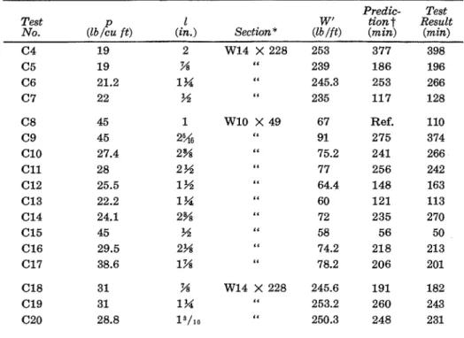
To examine the validity of the scaling method for so-called sprayed cementitious fire protection materials, a number of typical fire test results have been e~amined.~ As most materials containing cement or gypsum have a specXc heat in the order of 0.2, adherence to the previous assumption of adding one-half the heat capacity of the protection to that of the steel core amounts to using the unit weight per foot (W') of the structural unit in the scaling formula. Table 3 shows the calculated fire endurance times for the available fire tests.
Examination reveals that, in most cases, the results are reasonably close to the values derived by fire test. Considering that the information relating to density and other properties of the protective materials (which were similar but not identical products) was very scant, the agreement between predicted and test values is remarkably good. I t should be noted that the thermal conductivity of the protective materials was regarded as being independent of density in these calculations.
Predicfed Fire Enduranec (hr-min) 'Main Heat Sink - Sfeel Heat Sinl: Emphasized Method I Mehod 2 Merhorl 3 hlefhod .I
T i f Tmpczoid~zl Rrcfonguivr Cover Couer C o ~ e r Couer
Box PROTECTED STEEL COLUMNS
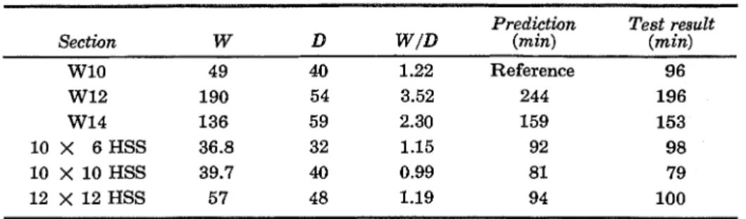
Most types of so-called "dry" column protection are applied in box form. The scaling formula has been applied for predicting the results of a con- trolled series of fire t e s t ~ , ~ as tabulated in Table 4. With the exception of the second set of figures, agreement between calculated and experimental results is excellent. The exception indicates the necessity for caution in using scaling to calculate fire endurance times much higher than that of the
TABLE 3 . Predicted and Test Results for Steel Columns Protected by Sprayed Cementitious Mixture
Predic- Test
Test P 1 W' tiont Result
No. (lb/cu f t ) (in.) Section * (lblft) (min) (min)
R e f . 275 241 256 148 121 235 56 218 206
*For section properties see Handbook of Steel Construction (Canadian Institute of Steel
Comtruction)
.
ttl/tZ = ( Z I W ' D Z / ~ Z W ' ~ D I ) ~ ~ ~
reference. Scaling relations should usually be used to calculate only fire endurance times equal to, or shorter than, that of the reference because s i g d c a n t deterioration of the protective materials may occur if fire ex- posure is prolonged.
Box PROTECTED STEEL BEAMS
Estimation of the fire resistance of protected steel beams is usually complicated by the fact that a typical floor deck makes a considerable contribution to the strength of a test a ~ s e m b l y . ~ With roof decks, which do not absorb much heat from the supporting beams nor contribute sig- nzcantly to structural performance, reasonably accurate estimates can be made. Table 5 shows the predictions for three identical wide-flange beams tested with a simulated roof deck.10
C O N C L U S I O N
A number of quantities in a heat conduction problem can be scaled, provided certain relationships are maintained. If the scale of tempera-
Sealing 203
TABLE 4. Predicted and Test ~ e s u l t s for Box Protected Columns*
Prediction Test result Section W D WID (min) (min)
W10 49 40 1.22 Reference 96 W12 190 54 3.52 244 196 W14 136 59 2.30 159 153 10 X 6 HSS 36.8 32 1.15 92 98 10 X 10 HSS 39.7 40 0.99 81 79 12 x 12 HSS 57 48 1.19 94 100
*Cover = 1-inch pressed vermiculite board, P = 27 Ibs/fta
ture is taken as invariant, the most useful relation is that time scales ac- cording t o the square of a characteristic dimension. I n applying this to fire resistance problems, the fact that a fixed furnace time-temperature curve is used may be largely overcome by taking the power law as 1.6 instead of 2. The relation involves the scaling of heat fluxes, although this is not directly compatible with cooling to the atmosphere. Where it is significant, as a t the unexposed surface of a wall, adoption of a higher exponent, par- ticularly where greater times are involved, can maintain the usefulness of the relation.
Scaling can be used quite extensively, and various applications are given. Its merit, apart from its simplicity, is that it does not require a knowledge of the thermal properties of the materials involved, takes ac- count of variation of thermal properties with temperature, and takes ac- count also of some of the effects of moisture. If, in fact, the migration of moisture followed diffusion laws, the scaling described would take account of all the effects of moisture.
A circumstance that will invalidate prediction by scaling is the in- volvement of a phenomenon that departs sharply from the relation. One example quoted involved the spalling of concrete t h a t occurred with disas- trous effect on a large-scale specimen, although not on smaller specimens. It might be wise, as a general rule, t o limit the application of scaling, where practical building designs are involved, to the calculation of fire endurance times equal to or less than that of the reference structure.
TABLE 5. Predicted and Test Results for Box Protected Steel Beams
Plaster thickness Prediction Test result (in.) (min) (min) *
Yi Reference 50
1 63 65
1 % 75 71
204
N O M E N C L A T U R E
x7 y and z = Cartesian coordinates
t = Time
e
= Temperature riseF z
= Heat flux through a defined area in the direction xk
= Thermal conductivityP = Density
c = SpecSc heat
4 = Scaling factor applied to dimensions in which there is a flow
of heat
m = Scaling factor applied to thermal conductivity k
n = Scaling factor applied to product pc
R7
r = Thermal resistancec,
c = Thermal capacityI = Thickness of thermal insulation protecting a column core
D
= Developed heated perimeter of thermal insulation protectinga core
A = Cross-sectional area of column core W = Weight per unit length of column core
W' = Weight per unit length of protected steel column
1, 2 = Subscripts relating to specimens 1, 2
= Subscripts relating to steel and concrete, respectively
R E F E R E N C E S
Lie, T. T. and Stanzak, W. W., "Fire Resistance of Protected Steel Columns," Engineering Journal, American Institute of Steel Construction, Vol. 10, NO. 3 (Third Quarter 1973), pp. 82-94.
Harmathy, T. Z. and Stanzak, W. W., "Behavior of Steel Flexural Members in Fire," Proceedings, Symposium on Applications of Solid Mechanics, University of Waterloo, Ontario (June 1972), pp. 291-310.
McGuire, J. H., "The Scaling of Dimensions in BS 476 Fire-Resistance Tests," FR Note No. 95, Joint Fire Research Organization, Boreham Wood, England (Janu- ary 1954).
"Fire Resistance Classifications of Building Constluctions," National Bureau of Standards, Building Materials and Structures Report BMS 92 (October 7, 1942), Appendix B.
Fire Research 1957, HMSO, England
Davey, Norman and Ashton,
b,.
A., "Investigations on Building Fires. Part V,Fire Tests on Stiuctural Elements, National Building Studies Research Paper NO. 12 (1953), HMSO, London.
Underwriters' Laboratories, Inc., Report to the American Iron and Steel Insti- tute, NC505, 71NK2639 (January 29, 1973).
Stanzak, W. W. and Lie, T. T., "Fire Tests on Protected Steel Columns with Different Cross Sections," NRCC 13072, National Research Council of Canada, Division of Building Research (February 1973).
Pearce, N. S. and Stanzak, W. W., "Load and Fire Test Data on Steel-Supported Floor Assemblies," S T P 422, American Society for Testing and Materials (August 1967), pp. 5-20.
l o Stanzak, W. W., "Fire Tests on Wide-Flange Steel Beams Protected with Gyp-
sum-Sanded Plaster," NRC 9474, National Research Council of Canada, Division of Building Research (June 1967).
Scaling
APPENDIX A
SCALING I N A ONE-DIMENSIONAL HEAT CONDUCTION PROBLEM
The flow of heat by conduction in a one-dimensional problem is governed by two equations:
F, = -
k.
sy. sz.ae/axand
( a F z / a x ) 6% = - PC. ax. ay. 62. ae/at.
(See list of nomenclature on page 204.)
If x, k and the product pc are scaled by the factors q, m and n, respec- tively, and 0 is left unscaled, then the equations will remain consistent
if
modified as follows:
( m / q ) F , = - mk. 6y. 6~6aiaqx
and
(a(m/q)F,/aqx) 6qx = - npc. 6qx. 6y. 6z.ae/a(nq2/m)t
Thus time t becomes (nq2/m)t and rate of flow of heat per unit area F z / 6y. 62
becomes ( m / q ) ( F z / 6y. 6 2 ) .
The dimensions y and z do not enter into the one dimensional problem and may be scaled by other factors. Such action would not affect t h e rate of flow of heat per unit area. It would remain ( F z / 6y 6 2 ) . It would, however,
scale total heat flux.
The same approach may be applied to the equations governing two- or three-dimensional heat flow. Time will again be scaled by the factor nq2/m, and flow of heat per unit area, by the factor m/q.
NOTE: This paper is published with the approval of t h e Director of t h e Division of Building Research, National Research Council of Canada, and of t h e Head of the Fire Research Station of the Building Research Establishment, Department of the Environment, and the Fire Offices' Committee, United Kingdom.
This publication is being distributed by the Division of Building Research of the National Research Council of Canada. It should not be reproduced in whole or in part without permission of the original publisher. The Division would be glad to be of assistance in obtaining such permission. Publications of the Division may be obtained by mailing the appropriate remittance (a Bank, Express, or Post Office Money Order, or a cheque, made payable to the Receiver General of Canada, credit NRC) to the National Research Council of Canada, Ottawa. KIA 0R6. Stamps are not ac- ceptable.
A list of all publications of the Division is available and may be obtained from the Publications Section, Division of Build- ing Research, National Research Council of Canada, Ottawa. KIA 0R6.