Publisher’s version / Version de l'éditeur:
Vous avez des questions? Nous pouvons vous aider. Pour communiquer directement avec un auteur, consultez la première page de la revue dans laquelle son article a été publié afin de trouver ses coordonnées. Si vous n’arrivez pas à les repérer, communiquez avec nous à PublicationsArchive-ArchivesPublications@nrc-cnrc.gc.ca.
Questions? Contact the NRC Publications Archive team at
PublicationsArchive-ArchivesPublications@nrc-cnrc.gc.ca. If you wish to email the authors directly, please see the first page of the publication for their contact information.
https://publications-cnrc.canada.ca/fra/droits
L’accès à ce site Web et l’utilisation de son contenu sont assujettis aux conditions présentées dans le site LISEZ CES CONDITIONS ATTENTIVEMENT AVANT D’UTILISER CE SITE WEB.
Paper (National Research Council of Canada. Division of Building Research),
1981
READ THESE TERMS AND CONDITIONS CAREFULLY BEFORE USING THIS WEBSITE. https://nrc-publications.canada.ca/eng/copyright
NRC Publications Archive Record / Notice des Archives des publications du CNRC : https://nrc-publications.canada.ca/eng/view/object/?id=5063a23c-cdd7-489f-88c9-db87497f21dd https://publications-cnrc.canada.ca/fra/voir/objet/?id=5063a23c-cdd7-489f-88c9-db87497f21dd
NRC Publications Archive
Archives des publications du CNRC
This publication could be one of several versions: author’s original, accepted manuscript or the publisher’s version. / La version de cette publication peut être l’une des suivantes : la version prépublication de l’auteur, la version acceptée du manuscrit ou la version de l’éditeur.
For the publisher’s version, please access the DOI link below./ Pour consulter la version de l’éditeur, utilisez le lien DOI ci-dessous.
https://doi.org/10.4224/40000463
Access and use of this website and the material on it are subject to the Terms and Conditions set forth at
Design and performance of a multi degree of freedom aeroelastic
building model
Ser
T L I
. \ ' ,B21d
'
no.
1008
,
National Research Conseil national
c. I Council Canada de recherche5 Canada
BLDG
DESIGN AND PERFORMANCE O F A MULTI-DEGREE- O F - F R E E D O M AEROELASTIC BUILDING MODEL b y J. T. T e m p l i n and K. R. Cooper R e p r i n t e d f r o m J o u r n a l of Wind E n g i n e e r i n g and I n d u s t r i a l A e r o d y n a m i c s Vol. 8 , 1981 p. 157
-
1 7 5 DBR P a p e r No. 1008 D i v i s i o n of Building R e s e a r c h P r i c e $1. 25 OTTAWACanads
NRCC 1SO MMAIRE
On a COnFU e t c o n s t r u i t , 'a 116chelle de 1/200e, un mod'ele
\a s e p t concentrations de m a s s e e t 'a t r o i s d e g r k s de l l b e r t 6 p a r ktage pour s i m u l e r l a tenue dynamique d'une tour 'a
b u r e a u x d c 57 .Ctages d e Toronto. O n d 6 c r i t a u s s i une m6thode qui p e r m e t d ' h l a b o r e r un mod'ele dans lequel 11 e s t tenu compte d e s modes coupl6s produits p a r l e dCcalage e n t r e l e c e n t r e de rigidit6 e t l e c e n t r e de m a s s e . Des m e s u r e s de l a r6ponse dynamique d u mod'ele indiquent que c e d e r n i e r p e r m e t d e bien s i m u l e r l e s p r e m i e r s modes fondamentaux de l a tour. Des r e s u l t a t s pr611minaires d ' e s s a i s e n soufflerie montrent que l a r6ponse d e t o r s i o n a un i m p o r t a n t effet s u r l e s d6placements. e t l e s acckl6- r a t i o n s m e s u r k s de l a s t r u c t u r e e t que p a r s u i t e l a r6ponse dynamique peut Etre s o u s - e s t i m 6 e s'il d e s t pas tenu compte de l a t o r s i o n .
Journal of Wind Engineering and Industrial Aerodynamics, 8 (1981) 157-175 157 @ Elsevier Scientific Publishing Company, Amsterdam - Printed in The Netherlands
DESIGN AND PERFORMANCE OF A MULTI-DEGREE-OF-FREEDOM' AEROELASTIC BUILDING MODEL*
J.T. TEMPLIN
Division of Building Research, National Research Council of Canada, Ottawa, Ontario (Canada)
K.R. COOPER
National Aeronautical Establishment, National Research Council of Canada, Ottawa, Ontario (Canada)
ANALYZED
SummaryA 1 : 200-scale, seven-level lumped-mass model with three degrees of freedom per floor has been designed and constructed t o simulate the dynamic behaviour of a 57-storey office building in Toronto. A model design procedure is described that allows for coupled modes produced by the effect of the offset of the centre of stiffness from the centre of mass. Measurements of the model's dynamic response indicate a good simulation of the first few fundamental modes of the building. Preliminary wind-tunnel result. show that torsional response has an important effect on the measured displacements and accelerations of the structure, demonstrating that dynamic response can be underestimated if torsion is ignored.
Notation
leg width in NS direction leg width in EW direction centre of mass
distance of elastic axis from origin of coordinates elastic axis (centre of stiffness)
east-west
Young's modulus force
bulk modulus
polar mass moment of inertia about centre of mass cross-sectional m>ament of inertia
torsional constant lateral stiffness
*Paper presented at the 4th Colloquium on Industrial Aerodynamics (Building Aerody- namics), Aachen, June 19-20,1980.
torsional stiffness
length; leg length (Model Design)
Lagrangian (T-U)
number of storeys (Design Theory)
mass (Model Design)
mass matrix moment north--south axial load
generalized coordinate generalized mode shape generalized force time
kinetic energy potential energy wind speed
EW leg location relative to local elastic axis NS leg location relative t o local elastic axis
EW and NS displacements vertical coordinate
critical damping torsional factor
angle about vertical axis stiffness matrix Poisson's ratio air density angular frequency Subscripts f full-scale
i, j referring to ith or jth floor
m model value x EW component Y NS component 0 torsional component Miscellaneous [ ]
-'
inverse of matrix ( ) first time-derivative ( ") second time-derivative ( ) model property1. Introduction
The dynamic response of a 57-floor office building in the heart of Toronto has been continuously monitored over the past three years [ I ] , and measure- ments of tip deflections and accelerations at four levels, including the top, have been made to provide comparisons with values in the National Building Code of Canada. As this full-scale measurement program offered an ideal opportunity for a correlation study with a model-scale wind-tunnel test, a joint program was initiated by the National Aeronautical Establishment and the Division of Building Research of the National Research Council of Canada.
A 1:200 scale model was designed for test in a 9.1 X 9.1 m closed-return wind tunnel using a spire-generated boundary layer. The model was a seven- level, lumped-mass approximation of the structure, having 21 degrees of freedom. Each of seven rigid masses was supported by four flexible legs providing one torsional and two independent lateral deflections. This arrange- ment allowed a good simulation of the First few coupled lateral-torsional modes of the full-scale building. This paper will concentrate on the design and laboratory testing of the model, but will present a few typical results from the wind-tunnel test.
2. Full-scale building description
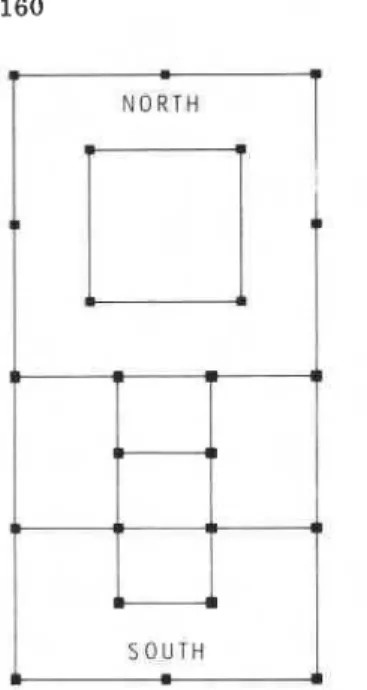
The Commerce Court West office tower is a steel frame structure with concrete floors. Stainless-steel and glass cladding and partitions are so de- signed that they do not add stiffness to the structure. The primary structure consists of frames in two directions, making use of 24 column lines extending the full height of the building. Although the exterior is symmetrical, the framing is not, because elevators and other services are located towards the south end and east-west (EW) frames are concentrated around them (Fig. 1). Some EW frames have K-bracing on the lower floors, but it does not extend to the top of the building. The stiffened frames are towards the south end, moving the centre of stiffness in that direction. The result is a centre of stiff- ness that shifts from south of the geometric centre of the building at the base to slightly north at the top. The building is symmetrical about the north- south (NS) centreline.
The mass properties (mass, moment of inertia, centre of mass) were derived from the 24 dead-load column loads for each storey supplied by the designers. A uniform live load of 480 N m-2 was used on every floor. This value is con- sistent with measurements of average live loads and represents actual condi- tions better than the extreme design case, which uses 95% confidence loads. As the centre of mass of each storey was less than 0.5% of the building length away from the geometric centre, it was assumed that the centre of mass and geometric centre of each floor coincide.
The stiffness properties of the building were obtained from the results of computer analysis, performed by the design engineers, of a plane-frame model
N O R T H
r-?
Fig. 1. Framing of 57-storey building.
of the structure loaded with estimated design wind loads. One calculation was made for each of the NS and EW directions using 1500-2000 representative members and joints in each case. The P-delta effect was included t o account for an increase in flexibility resulting from the weight of the structure. A rigid foundation was assumed. Based on these calculations it was determined that the structure acted primarily as a shear building; there was very little column shortening or floor rotation. The ratio of successive frequencies for a simple shear structure is 1: 3 : 5, as was the case in the full-scale building. The assumption of pure shear behaviour considerably simplifies further analysis.
Lateral stiffnesses in two directions were determined for each floor, using applied loads (without the P-delta effect) and the resulting lateral deflections. To obtain torsional information from the plane-frame analysis, the shear forces in the 24 columns due to the EW wind loads were used t o calculate the shear centre of each storey. The torsional stiffness about the shear centre was determined by applying a fictitious rotation of each floor about its shear centre and calculating the forces required to deflect each column, based on measured shear forces from the NS and EW loading cases. This implies that all rotational stiffness is due to bending stiffnesses of the frames and not t o torsional stiffness of the columns. The stiffnesses were adjusted using the combined dead and live loads to include the P-delta effect.
The properties of this 171-degree-of-freedom numerical representation of the building were used in a dynamic analysis program to determine the natural frequencies and mode shapes of the structure. The resulting calculated funda-
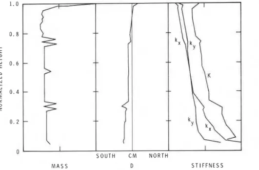
mental frequencies were 15-20% lower than those measured in full scale [ I ] , implying that the calculated stiffnesses were low. In fact, later analysis by the designers showed an increase of this order in the fundamental frequencies as a result of fireproofing and a better estimate of floor-slab stiffness. A con- stant stiffness was therefore added t o each floor in order to obtain the correct frequencies of the lowest three modes (two lateral and one torsional). The assumed properties of the building used for subsequent calculations are shown in Fig. 2. Irregularities in the mass distribution occur at mechanical floors where there are changes in framing that affect elastic axis location and stiff- nesses.
M A S S D S T I F F N E S S
Fig. 2. Full-scale building properties (arbitrary units).
3. Design theory
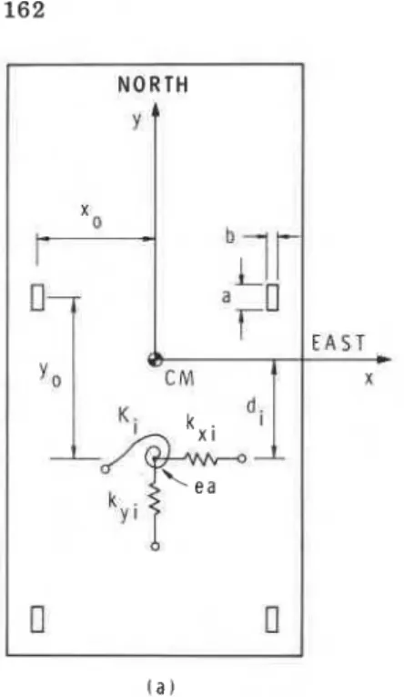
The theory provides a rational approach to designing a simplified model of a multi-storey structure that retains the complex dynamics required for a realistic wind-tunnel simulation. The model consists of rigid floors, containing most of the mass, connected by light-weight flexible members. The geometry of a typical floor is shown in Fig. 3. The centre of mass (CM) is located at the geometric centre, the origin of the coordinates. The three characteristic stiff- nesses for the ith floor are represented by springs with ends attached to the elastic axis on the ith floor and t o the (i-1)th floor below it, producing forces resulting from relative displacement of these floors. The elastic axis is located a distance d , from the origin, positive in the south direction (-y).
N O R T H
Y '
X 0t
t r r r X d . I0
n
l a ) F L O O R i + 1 rFig. 3. Definition of model geometry.
Because the elastic axis is always on the y-axis for this structure, the NS motion is decoupled from the EW and torsional movements, allowing two problems to be formulated, one for the NS motion and one for the EW- torsional motion.
For the EW-torsional case consider forces
F i
and momentsM i
applied at the centre of each floor. In matrix form:where K is a partitioned stiffness matrix. A displacement
xi
of the ith floor with all rotations and all other lateral displacements kept at zero will produce a force at the ith floor ofwhere ki is the lateral spring constant k , of the ith floor. This force must be counteracted by a moment to prevent rotation:
For a rotation
6
of the ith floor with no lateral displacement or other rota- tions, both forces and moments are required.A
force of-k6d
is required to rotate the floor about the origin when the centre of stiffness is a distanced
from the origin. Owing t o additional stiffness from the floor above, the re- quired forces are
Fi-l
=d i
k i
O i ;
Fi+l
=di+,
hi+,
Oi
(7)r
The moments required to overcome the torsional stiffness plus the moments due to lateral forces are
1
Each partition of the coupled stiffness matrix in eqn. (1) is a tri-diagonal symmetric matrix. The non-zero elements of the ith column for each partition for the (i-l)th, ith and (i+l)th rows, respectively, are:for K :
-hi
;hi
+k i + ~ ;
-ki+~
(10)When
i
= 1 , the (i - 1)th row is ignored. Wheni
= n, the (i+l)th row is ignored and the (i + 1)th terms are set to zero.The NS case does not involve moments or rotations and the stiffness matrix is only K
,
(eqn. (lo)), wherek i
is theNS
lateral stiffnessk,
of the ith floor.The mass matrix for the system chosen where the centre of mass is at the origin for each floor is a simple diagonal matrix with elements m i in the upper half and
Ii
in the lower half for the EW-torsional system. For the NS system, only the masses m i are required.The equation of motion can be formulated using these stiffnesses and masses and the generalized coordinates
qi,
as follows:where [I] is the identity matrix. This eigenvalue problem can be solved for values of w and
q
using any suitable digital solution method.I
A model with the same hequencies and mode shapes as the full-scale struc- ture but fewer mass and stiffness elements is desired. This can be accomplished I through an application of Lagrange's equations using the concept of generalizedproperties where the model is designed t o have correctly scaled kinetic and potential energies. The potential energy for the structure with n floors is
where A(xi
-
Bidi) is the relative displacement of the elastic axis from its rest position. The potential energy is due to lateral displacement of the elastic axis as well as twist of each floor. The kinetic energy isFor a particular mode shape assume
x = q , ( t ) @ , ( z ) ; d = ~ e ( t ) @ e ( z )
where q, and qe vary only with time and @, and
Ge
represent constant modeshapes. Lagrange's equations are
where the Lagrangian L is given by
where A@, = @x,i - $,,i-1 and A@e = G0.i - @e,i-l.
Using eqn. (18), eqn. (17) can be written as
For two systems to be dynamically similar, the coefficients of the equations
of motion must be identical. Thus, to model an n-storey building by an
m-
storey building, where m
<
n, the summations (generalized properties) in eqns.(19) and (20) must be equal for both structures. These equations must be applied for each mode shape that is to be duplicated.
For m = 1 (single storey), the relation is simplified since the mode shapes
reduce to constant scalar values and the model properties m', kt, I t , d
',
and K 'can be evaluated explicitly. For m
>
1 there may not be a physically realizablesolution. For
m
sufficiently large, however, a solution producing a goodapproximation of the lower modes can be found. The method used for the current design matches portions of the n-storey structure to the individual modules of the m-storey model. The following equations are formulated:
j z
(k; di2 + K ~ ' ) A @ ; ~ ~ =
C
( k i d i 2 + K i ) A@ei2 ,=j( 2 5 )
where these are used t o evaluate the properties of the jth module of the model and jl and j2 are the lowest and highest storeys of the n-storey structure that are to be included in the jth module. The values of mode shape are chosen from the lowest fundamental modes. The choice of j, and j2 can be arbitrary and is determined by the requirements of the test.
I
4. Details of model mechanical designOnce the model-scale structural system and the number of modules re- quired have been selected, the design theory can be used t o determine the necessary generalized properties. These properties can be adjusted to model scale and used to design the mode1 components.
The number of modules chosen will depend on many parameters, including: number of modes required; distribution of and discontinuous changes in mass, inertia, stiffness or cross-sectional shape with height; number of measurement levels required; model structural requirements; and model complexity.
In this instance, four upper-level breaks were required for accelerometers and displacement transducers to represent the locations used at full scale
( 1 3 8 m, 166 m, 201 m, 235 m), and one lower break was required to handle a
structural change (77 m). Because the two lower modules were tall, i t was decided to divide each of them in two ( 4 3 m, 102 m) to reduce potential problems of lack of stiffness in the light-weight facade used to provide the correct aerodynamic shape. Seven modules were required in total, permitting a good representation of the first two structural modes.
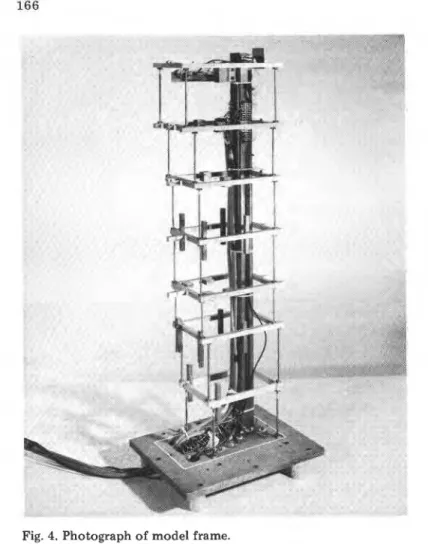
The full-scale building deflections consisted primarily of shearing of adja- cent floors in parallel planes, with no significant column shortening. The model structure used to simulate these deflections consisted of four identical
Fig. 4. Photograph of model frame.
rectangular legs per module, sized and spaced t o provide the requisite lateral stiffnesses, torsional stiffness, and elastic-axis offset. The legs were ground to size within 0.01 mm and silver-soldered to brackets at each end that were fastened to the floor masses or base plate with four small cap screws. The rigid floors were designed to be several orders of magnitude stiffer than the
.
legs and contributed most of the mass and mass moment of inertia requiredfor each module. The exterior shape of each module was provided by 1.6-mm thick balsa sheet stiffened with balsa and aluminum. This facade was rigidly
r attached near mid-height to the module mass and separated from adjacent
elements of the facade by a 1.6-mm gap. This gap was later taped over and the tape slit t o reduce air leakage. Although the facade design and construc- tion seemed straightforward at first, it was not. In particular, warping posed considerable problems even after the balsa was sealed. A superior form of construction would probably involve laminated balsa or balsa-foam sandwich panels. The floor masses were initially designed to provide about two thirds of the required mass and inertia, the remainder being provided by the facade and sets of trim weights. The effective masses of the legs and brackets were included as part of the floor masses. The model was attached to a 25-mm thick steel base-plate that, in turn, was bolted to a rigid turntable isolated from wind-tunnel shell vibrations by air springs.
The upper module was instrumented with both inductive displacement transducers and miniature accelerometers. The next two modules were fitted with accelerometers only and the legs of the first level were strain-gauged.
A single instrument or strain-gauge bridge was used in the NS direction,
while the sum and difference signals from pairs of transducers were used to
obtain EW lateral motion and torsion. The instrumentation leads and motion
transducers were supported by a rigid inner tower whose natural frequency - -
was well above model frequencies of interest. The major structural details of
the model frame can be seen in Fig. 4. Figure 5 shows details of a typical floor
mass, the top floor, including instrumentation.
The aeroelastic similarity or modelling laws used to convert the full-scale
generalized building properties t o model scale are summarized in Table 1.
The velocity scaling can be arbitrarily set and was chosen as 1: 3.5 t o keep the
frequencies of the first two EW modes below 1 0 Hz, resulting in a model
stiffness well below that of the mounting system. The model legs were still large enough for easy machining and strain-gauging, and the floor/leg stiffness ratio was high.
The sizing and location of the elastic legs is set by the model size and the velocity scaling selected through the modelling parameters of Table 1 and the
1 stiffness properties required. A typical mode of deflection for the legs of one
floor is schematically illustrated in Fig. 3 which also includes a sketch defining the leg geometry and location. The deflected shape of each leg is identical to that for two cantilever beams, one extending up from the lower floor and one down from the upper floor, joined at their tips. The lateral stiffness of a single leg is given by
168
TABLE 1
Modelling parameters
Property Modelling parameters Value used length velocity time density mass inertia force bending stiffness moment torsional stiffness damping
Thus the lateral stiffnesses for four legs are
k: = 4 a E ( b / l ) 3
kk = 4 b E ( ~ / l ) ~
When the effect of axial load is included, the lateral stiffnesses become
The torsional stiffness, arising from a combination of twisting and lateral deflection, is given for four legs by
= lztwist + kbend
= ( 4 GJIl) + ( k , y i +
k,
x i )The bulk modulus is assumed to be
and the torsional constant is
where q is the function of alb shown in Fig. 6 [2], used to adjust the torsional
a l b Fig. 6. Torsional factor, q.
Knowing the required values of k , , k , and K obtained by scaling the prototype
structural values, it is possible to solve for a , b ,
xo
and yo. Leg lengths are setby floor mass location, thickness, and mounting-bracket size. The leg sizes are given by
b = { ( k , + P/l)13 I(4E [ ( k , + P / l ) / ( k , + ~ / 1 ) ] 3" 4) I'} ( 3 5 )
a = b [ ( k , + P / l ) / ( k , + P / l ) ] ' I 2 ( 3 6 )
The value of
x o
was set t o a convenient constant value at each floor and eqn.( 3 4 ) was solved for y o :
y o =
{[K
-
(4l?/2.61)(ab3/3 - q b 4 ) - k y x ; ] kw -l}ln ( 3 7 )The leg locations were then obtained by shifting the geometric centre of the leg array by the required generalized elastic-axis offset.
The model legs were from 3.12 to 4.87 mm in width and from 100 to 159
mm in length. The values of y o ranged from 110 t o 152 mm with
x o
chosento be 7 6 . 2 mm.
5. Measurement of model properties
Prior to installation of the model in the wind tunnel a series of laboratory measurements was .made to determine the model's static and dynamic proper- ties in order to enable trim-weight positions and masses to be computed and to establish whether expected model-scale properties had been achieved.
Each module was assembled, including all components except the legs, and the module's mass and centre of gravity were determined. The polar moments of inertia about the mass centre were determined using a quadrafilar pendulum.
The location and size of the trim weights required to provide the final values of mass, inertia, and centre of gravity location were determined, the weights were mounted on the floor masses and a final set of measurements taken. The bending and torsional stiffnesses of each floor were measured by loading each floor assembly (set of legs and adjacent floor masses) with pure forces and moments and measuring the resulting deflections.
The measured stiffness properties were, on average, 1-2% below those re- quired, probably due to bending of the floors. Although the floors had been
considered rigid in the design analysis, the effect of finite stiffness was shown +
to reduce stiffnesses by 2-6%,depending on the floor. The masses and mom-
ents of inertia averaged within 0.5% of the required values.
The model was completely assembled and bolted to a rigid foundation for preliminary dynamic testing. Aluminum-foil targets were attached to each floor, and travelling inductive-displacement transducers were used to measure the motion of each module of the model, which was excited by a linear- motion, electrodynamic shaker acting through a weak spring. This spring de- coupled the shaker mass from the model and limited the maximum force applied. The shaker spring introduced an additional peak in the measured response spectrum because of its first-mode resonance, but this was filtered out. White-noise excitation was used to determine the model's natural fre-
quencies, and typical spectra showing the first seven EW modes and the first
F R E Q U E N C Y . H z
TABLE 2
Comparison of measured and required model frequencies
Model equivalent of full scale Computed model Measured model, 5 = 0.0025 Measured model, 5 = 0.01 (9.1 x 9.1 m wind tunnel) EW Mode NS Mode
*Frequency ratio in parentheses.
three NS modes are given in Fig. 7. The model was then shaken at these fre- quencies with a sinusoidal input and the resulting mode shapes measured.
The measured model frequencies are compared with those of the computed model and the measured full-scale values, converted to model-scale, in Table 2. The E W modes are grouped in sets of two modes. The pairs are a result of inertial coupling in the E W direction due to the offset of the elastic axis and the centre of mass of the building. The lower mode of each pair is primarily lateral, with a smaller torsional component, whereas the higher mode of the pair is primarily torsional with a smaller lateral component. The ratio of the torsional-to-lateral natural frequencies are also given in parentheses for the E W modes in Table 2. The NS modes are lateral with no torsion and generally have a frequency close to that for the E W lateral modes.
The choice of model natural frequency was difficult to make because the full-scale building's periods increased with mean wind speed [I] .The model frequency was chosen to match that measured with an
18.4
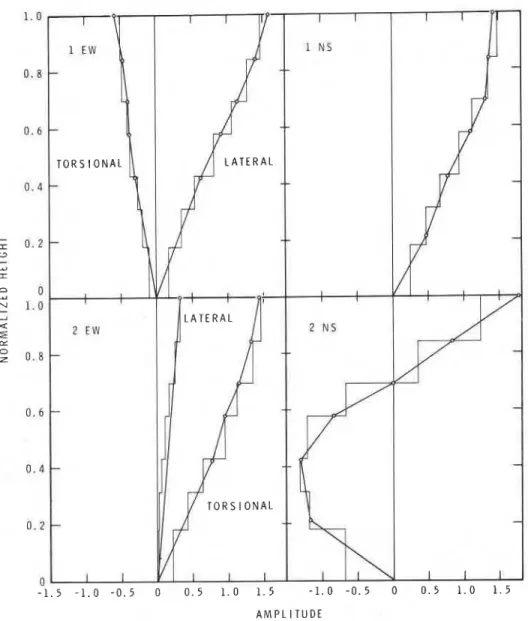
m s-I wind at full scale, equivalent to the lowest speed at which the model was to be tested.The first two measured NS and E W model mode shapes are compared with preliminary measurements from the full-scale structure in Fig.
8.
In all cases the mode shapes are scaled so that the integral of the mode shape squared over the height of the building equals1.0.
The torsional components at each level were converted to an equivalent E W deflection at a horizontal distance of34
m measured north from the geometric centre of the building, at a point almost at the outer wall where accelerometers were located on the upper floors of the full-scale building. The computed model mode shapes were within a few percentage points of the measured values.The preceding measurements were made at a damping level of 0.0025 in the fundamental modes, lower than the value of { lEw = 0.01 measured for the
full-scale building [I]. Additional'damping was provided by the addition of foam-rubber pads between adjacent sections of facade. The foam could be positioned t o adjust the damping separately in the first two EW modes and the first NS mode, and served t o reduce leakage flows through the slots separating adjacent sections of the model facade. The foam pads increased the model stiffnesses slightly, as shown in the last row of Table 2. The final
A M P L I T U D E
damping levels obtained were
SlEW
= 0.0096,tzEw
= 0.0104 andClNS
= 0.0105. The damping measurements were obtained from vibration-decay tracesproduced after the shaker was turned off.
6. Preliminary wind-tunnel results
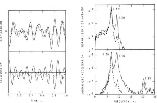
Although the data from the recently completed wind-tunnel tests will re- quire detailed analysis, it is already apparent that torsional motions have a considerable influence on the observed deflections and accelerations. Compar- isons of the EW motion of the north wall, resulting from lateral deflections alone, with the motion produced by a combination of lateral and torsional deflections indicate a considerable increase due t o torsion, especially for acceleration (Fig. 9). The data represent a typical cross-wind response to south winds of 39.3 m s-' full scale at a 300-m reference height. The response and acceleration spectra of the records from which the sample signals were chosen (Fig. 9) clearly show the significance of the second EW mode of vibra- tion. If the torsional deflections had not been simulated, the standard devia- tion of acceleration at the building's north wall would have been only 47%
of the value observed. For other wind directions except near north the increase due t o torsion would be less than given in this example, but would still be sig- nificant. Table 3 summarizes the standard deviations of deflection and accelera- tion of the north wall measured for this example.
T I M E , s F R E Q U E N C Y , Hz Fig. 9. Effect of torsion on north wall deflection and acceleration in model: -, lateral and torsional; - - - - -, lateral only.
TABLE 3
Standard deviation of EW response (arbitrary units) EW Torsion EW plus torsion
Displacement 0.218 0.132 0.266
Acceleration 0.155 0.270 0.333
7. Concluding remarks
A method of designing a multiple-degree-of-freedom building model is presented that accounts for the distributed properties of the building, including torsion. The generalized properties of portions of the full-scale structure are represented by individual modules of the model, each having correctly scaled mass and stiffness properties. A model was designed of a 57-storey office tower with coupled lateral and torsional modes of vibration. The simplest geometry that can include the torsional behaviour would be a linear-mode, pivoted model having a rigid-body torsional degree of freedom. This singlemodule model would provide tip deflection and base moment only. A more complex 7-module, 21-degree-of-freedom model was chosen to permit detailed comparison of motions on other levels of the full-scale stmc- ture. Laboratory measurements of the model's mode shapes and natural fre-
quencies agreed well with full-scale values, demonstrating a good dynamic simulation and verifying the design procedure.
An indication of the importance of torsion to the model building's dynamic response is provided by preliminary wind-tunnel results. Peak values of both deflection and acceleration were increased as a result of the torsional compo- nent of building motion. These increases suggest that torsion should be con- sidered in aeroelastic model design if peak dynamic responses are not to be underestimated.
Acknowledgements
The authors wish t o express their grateful thanks to the following organiza- tions and individuals for their contributions to this paper: Canadian Imperial Bank of Commerce, owners of the building; John Springfield, of Carruthers and Wallace Consulting Engineers, for design information; members of the
Low Speed Aerodynamics Section, National Aeronautical Establishment; and
1
colleagues in the Division of Building Research, particularly J.H. Rainer forsupplying full-scale mode-shapes. This paper is a joint contribution of the ! National Aeronautical Establishment and the Division of Building Research,
National Research Council of Canada. It is published with the permission of the Directors of both Divisions.
References
1 W.A. Dalgliesh and J.H. Rainer, Measurements of wind induced displacements and accelerations of a 57storey building in Toronto, Canada, Natl. Res. Counc. (Canada), Div. Build. Res., NRCC 17152 (1978).
2 C.F. Kollbrunner and K. Basler, Torsion in Structures, Springer, Berlin, 1969, pp. 268-269.
This publication is being distributed by the Division of Building R e s e a r c h of the National R e s e a r c h Council of Canada. I t should not be reproduced in whole o r in p a r t without p e r m i s s i o n of the original publisher. The Di- vision would b e glad to b e of a s s i s t a n c e in obtaining s u c h p e r m i s s i o n .
Publications of the Division m a y be obtained by m a i l - ing the a p p r o p r i a t e r e m i t t a n c e ( a Bank, E x p r e s s , o r P o s t Office Money Order, o r a cheque, m a d e payable to the R e c e i v e r G e n e r a l of Canada, c r e d i t NRC) t o the N a t i o n a l R e s e a r c h Council of Canada, Ottawa. K1A OR6. Stamps a r e not acceptable.
A lie t of a l l publications of the Division i s available and m a y be obtained f r o m the Publications Section, Division of Building Research, National R e s e a r c h Council of Canada, Ottawa. KIA OR6.