Publisher’s version / Version de l'éditeur:
Vous avez des questions? Nous pouvons vous aider. Pour communiquer directement avec un auteur, consultez la
première page de la revue dans laquelle son article a été publié afin de trouver ses coordonnées. Si vous n’arrivez
pas à les repérer, communiquez avec nous à [email protected].
Questions? Contact the NRC Publications Archive team at
[email protected]. If you wish to email the authors directly, please see the
first page of the publication for their contact information.
https://publications-cnrc.canada.ca/fra/droits
L’accès à ce site Web et l’utilisation de son contenu sont assujettis aux conditions présentées dans le site
LISEZ CES CONDITIONS ATTENTIVEMENT AVANT D’UTILISER CE SITE WEB.
Proceedings, International Symposium on the Mechanical Behaviour of Structured
Media, pp. 419-430, 1981
READ THESE TERMS AND CONDITIONS CAREFULLY BEFORE USING THIS WEBSITE.
https://nrc-publications.canada.ca/eng/copyright
NRC Publications Archive Record / Notice des Archives des publications du CNRC :
https://nrc-publications.canada.ca/eng/view/object/?id=8992175b-9883-43d0-a268-7daa377be5f7
https://publications-cnrc.canada.ca/fra/voir/objet/?id=8992175b-9883-43d0-a268-7daa377be5f7
NRC Publications Archive
Archives des publications du CNRC
This publication could be one of several versions: author’s original, accepted manuscript or the publisher’s version. /
La version de cette publication peut être l’une des suivantes : la version prépublication de l’auteur, la version
acceptée du manuscrit ou la version de l’éditeur.
Access and use of this website and the material on it are subject to the Terms and Conditions set forth at
Deformation behaviour of ice-like materials in engineering applications
Sinha, N. K.
-
Ser
N21d
National Research
Conseil national
no. 992
I
*
Council Canada
de recherches Canada
c .
2
'
DEFORMATION BEHAVIOUR OF ICE LIKE
MATERIALS IN ENGINEERING APPLICATIONS
by
N.K.
Sinha
ANALYZED
10253
Reprinted from
Proceedings, International Symposium on the
Mechanical Behaviour of Structured Media
Ottawa, Canada
18 21 May 1981
p.419 430
DBR
Paper No. 992
Division of Building Research
SO
MMAIRE
Cet a r t i c l e dCcrit comment, g r 2 c e
'a
une 6quation de fluage,
on peut p r g v o i r 18Cvolution d e l a dCformation de mat6riaux
p o l y c r i s t a l l i n e
'a
de hautes t e m p & a t u r e s homologues, quand
i l s sont s o u m i s aux sollicitations v a r i a b l e s q u e l ' o n r e n c o n t r e
habituellement dans l e s applications techniques. L a p r C v i s i o n
th6orique a CtC comparCe avec succ'es
5
d e s o b s e r v a t i o n s
expCrimentales d e l a glace. On trouve Cgalement dans c e t t e
communication une analys e de 18application tr'es s a t i s f a i s a n t e
d e 18Cquation proposCe
'a
l a d e s c r i p t i o n de l a rkponse dyna-
mique observCe pour l a glace polycristalline.
On y t r o u v e
a u s s i une explication d e s mCcanis m e s physiques qui i n t e r
-viennent d u r a n t l a dCfor m a t i o n d e matCriaux m u l t i g r a n u l a i r e s
Mechanics of Structured Media, Proceedings of the International Symposium on the Mechanical Behaviour of Structured Media, Ottawa, Canada, May 18-21,1981 Part
A,
pp. 419-430Elsevier Scientific Publishing Company, Amsterdam - Printed in The Netherlands
DEFORMATION BEHAVIOUR OF ICE-LIKE MATERIALS IN ENGINEERING APPLICATIONS
N.K. SINHA
Geotechnical Section, Division of Building Research, National Research Council of Canada, Ottawa, Ontario, Canada KIA OR6
ANALYZED
ABSTRACTThis article describes how a creep equation can be applied to predict the deformation behaviour of polycrystalline materials at high homologous temperatures, subjected to variable loading conditions common to engineering applications. The theoretical prediction has been successfully tested with experimental observations made on ice. The paper also discusses the successful application of the proposed analytical expression to describe the experimentally observed dynamic response of polycrystalline ice. An explanation of the physical processes that take place during the deformation of multigrained materials at high
tenperatures is presented.
INTRODUCTION
Isotropic snow-ice is structurally similar to many commonly used engineering materials, whereas commonly occurring columnar-grained sea ice is not different in texture from directionally frozen super alloys. Metals, alloys, clays, ceramics and many other polycrystalline materials usually have grain sizes in the range of a few micrometres. In comparison, the grain size in natural ice has been observed to be in the range of a few millimetres.
- -,-- --\
In most engineering problems involving ice, %hear stress,
21-
ranges from a- 2
fraction to a few MN.m
.
This is relatively low if only the absolute magnitude of the stress is considered. However, the corresponding normalized stress, T/G, where G is the shear or rigidity modulus,is comparable to the normalized stress other materials are subjected to during their service life.The temperature of ice in nature rarely goes below - 4 0 " ~ for any extended period. Working temperatures in ice are, therefore, greater than the homologous
temperature of 0.85 Tm, where T is the melting point in kelvin. High temperatur m
in metals and alloys are considered to be around 0.4 T or above. Ice, therefore m
normally exists in a high temperature state.
A better appreciation of the deformation behaviour of ice can be obtained by comparing its response with that of other materials of similar grain structure and texture at similar homologous temperatures and normalized stresses. Studies on the mechanical properties of ice, on the other hand, also give an improved understanding of the behaviour of other polycrystalline materials under comparabl conditions.
This paper describes briefly, albeit superficially, the micromechanics of
-
.--
-
-- -
polycrystalline materials and presents an analytical expression to describe theI
-- -
----
-
-
\
phenomenological observations under uniaxial creep loading Dondltions. It also - -
describes how the creep equation Can be applied to predict the uniaxial deformati behaviour of materials that are subject to variable loading conditions common to
engineering tests. Both theoretical predictions and experimental observations will be used to show that polycrystalline materials might exhibit properties at high temperatures which, although apparently peculiar, can be explained and quantified.
ENGINEERING TESTS
Two comnonly applied experiments to determine material properties for engineer ing applications are the uniaxial "constant stress" creep and the "constant strai rate" deformation tests. Ideally a certain stress is suddenly imposed and held constant in the creep tests; in the other tests, a certain strain rate is sudden1 imposed and held constant. There is a profusion of either empirically developed or theoretically formulated mathematical equations to describe constant stress creep, as well as constant strain rate deformation experiments. These equations often add to the confusion, although efforts have been made (ref. 1) to show that most creep equations are at least related to each other. Using a creep equation to predict the response to a variable load, or vice versa, is still an open question. Moreover, many empirically developed equations give no consideration to the structure and texture of the material or the physical processes occurring during the deformation process.
PROPOSED CREEP EQUATION
Irrespective of material differences or operational conditions, the total strain, E , can be physically described in terms of a minimum of three macroscopic strain components - a pure elastic and instantaneously recoverable deformation, ee, a delayed elastic or time-dependent recoverable strain, E ~ , and a permanent
or viscous strain, E
.
In the case of creep at constant stress, o, and vtemperature, T, E is dependent on time, t, i-e., E = E~ and
Elastic response of a single crystal is described by a number of elastic moduli corresponding to the different lattice planes. Polycrystalline materials, on the other hand, exhibit a mixed single crystal elastic response. This elastic response is referred to above as 'pure elastic' and is usually represented as Young's modulus, E, and shear modulus, G. Thus E in the previous equation can
e -
be replaced by o/E, assuming the applicability of Hooke's law in uniaxial loading.
Stress induced and thermally activated mobility-af defects (vacancies,
i- '
___
4----_._interstitials, dislocations, etc.,) governs bi,scous . creep--&..single ....-<.' , , crystals as well as in individual grains in polycrystals. diaxik boundari?; in polycrystalline materials add additional complexities and act as barriers, sources or sinks to these intragranular _def_e_cts;--4ingle as well as polycrystals exhibit, however,
-1 ~\
small or negligible delayed elasticbnrecove;; creep at'low temperatures. Shear ' \ or sliding in the grain boundary regions becomes pronounced at temperatures of
1
about 0.4 T and above, as does the amount of recovery strain. Moreover,i
m -2
recovery effect becomes more pronounced in polycrystals than in single crystals. This author hypothesized that a degree of reversibility in the grain boundary sliding processes, including its accommodation, might be associated with delayed elasticity. This effect in ice of known grain size was experimentally investiga- ted and formulated (ref. 2), but no information is yet available on intergranular
- - I
displacements in polycrystalline ice. An indirect approach was then taken to
I
I
correlate the delayed elastic strain to the strain due to the grain-boundary
I
sliding, for metals, alloys and other materials (ref. 3 ) . The result was the
\
-.-- development of a mathematical model capable of explaining satisfactorily the observed dependence of sliding on stress, time, strain, temperature and grain size (ref. 3). This analysis also assisted in introducing the influence of grain size on the creep of polycrystalline materials at elevated temperatures. It was concluded that, for conditions where the microstructure had not deteriorated--.
because of voids, cracks or recrystallization, etc., the viscous creep rate,
i
rv' was independent of grain size, in direct contradiction to the usually accepted a - ' concept (refs. 4, 5), and that the transient creep rate should be sensitive to grain size. Grain size insensitivity of E ~ , in ice in the range of grain diameter d = 1 to 10 mm, usually encountered in nature, has since been verified experimen- tally (ref. 6) at 0.97 Tm (-7OC). An excellent example of the effect of grain size on transient strain during creep in an iron-base austenitic alloy at 0.55 T m
422
- - - - - - -
-
-
~ h d u n i a x i a l
.
creep equation in polycrystals\can now be described. The totalstrain, E ~ , at time, t, in pure randomly oriented, polycrystalline material of -
-.
grain size, d, subjected to an uniaxial stress, cr, at a temperature, T, is given
by
E = - + cl
k]
[;Is
- exp { - (aTt) b11
+tv
1
9In
where E is Young's modulus; E is the viscous strain rate for unit or reference
v 1 1
stress, u ; cl is a constant corresponding to the unit or reference grain size,
dl; b, n and s are constants; and a is a constant at a given temperature. The T
constant n represents the stress exponent for viscous flow; s is implied as the stress exponent for delayed elasticity or grain-boundary sliding.
Both iv and a are dependent on temperature, such that
1 T
and
where Q and R are the activation energy and gas constant respectively; and TI and
T are temperatures in the kelvin scale. 2
- , The three components in Eq. (2) correspond to the three components ~n Eq. (1)
! respectively. Equation (2) has been shown to be applicable both in compression
(ref. 2) and tenslon (ref. 3). It should not be extrapolated to long-term creep without consideration of its limitations, as discussed (ref. 3). The values of
the factors in Eq. (2) for ice were determined (ref. 3) to be E = 9.5 ~ N - r n - ~ ;
Q = 67 kJ/mol; cl = 9; n = 3; b = 0.34; s = 1; aT (T = 263 K) = 2.5 x s-l;
6
= 1.76 x s-l at T = 263 K; u1 = 1 M N . ~ - 2 ; and dl = I mm. These valuesv1
will be used in the theoretical predictions in this paper, although it is believe
.'(-'that the constants can be determined with greater accuracy.
VARIABLE STRESS LOADING
"Constant stress" uniaxial creep tests are usually performed at constant load
I
i using a dead-load system. Stress can be assumed to be constant as long as the
specimen is not allowed to deform excessively, e.g., not more than a few per cent. A constitutive creep equation for constant stress can therefore be developed with reasonable confidence. Until recently, "constant strain rate" tests were
performed at constant cross-head or actuator rates, j r , using conventional test
machines, and the actual specimen strain rates,
t ,
were far from constant (ref. 7 ) .The deviation of E from the nominal strain rate in(= %/9. where R is specimen
length), could depend on the capacity and hence the stiffness characteristics df the machine (ref. 8). Any equation developed from the observations under such conditions, with the assumption of a constant strain rate, is applicable only to the results of that particular system (ref. 9) and may not be generalized. The results, however, can be examined with respect to the imposed stress or strain path. An effort will be made next to show how Eq. (2) can be applied to predict the uniaxial deformation behaviour under variable loading conditions.
/'-
I
-
Any arbitrarily increasing stress path can be represented in terms of-sseriesof positivYee
-
stqes_svaWs'each acting during an equal interval of time, At.Suppose Aol,
Au,
.
.
.
LoN, and are the incremental increases in stress attimes 0,At.
. .
(N-l)At, NAt so that Aol is the average stress in the firstinterval of time, Aol
+
Ao, in the second interval, and so on. Stress Aol appliedat t = 0 produces, according to the first term in Eq. (2), an instantaneous
elastic strain Ao /E at t = O+ with negligible contributions from the second and
1 the third term. Thus
There will be an elastic strain due to the total stress of nol
+
Au2 at t = lilt',whereas the delayed elastic and the viscous strains will be the amounts produced
by
AD,
applied for t = l ~ t + . Hence, from Eq. (2) at t = at+, one obtainsAu
+
Aa,E = 1
t E (4b)
At t = 2ntf,elastic strain will correspond to the stress
AU
+
Au2+
A u ~ .1
Viscous strain will be the sum of the strain produced by ADl applied for the first
increment of time At and the strain produced by Ao
+
nu2 applied for the secondincrement of time At. This is on the assumption that the "commutative law" of creep (ref. 10) applies to viscous flow. Such a law is independent of history
424
and cannot be applied to delayed elastic strain, particularly if associated with grain boundary sliding. A detailed discussion on this question and a method of generalized calculation will be presented elsewhere. It will be assumed that the principal of superposition associated with a standard linear solid is applicable
I for the class of polycrystalline materials that exhibit linear stress dependency
in their delayed elastic response, i.e., s = 1. Accordingly, the total delayed
elastic strain at 2btt is given by the sum of the strains produced by Aol applied
for 2At and Aa2 for At. Thus at t = 2bt' and s = 1, the total strain is given by
Ao,
+
Ao2+
AoE =
t E
+
c 1[>I
p
- exp ;- (a T 2At)"1
1
+
- 1-
expI-
(a At)1
+
EE
Ao2
L-
.I]
v1 At+
A"]~]
(4c)Equation ( 4 c ) can be expanded to show that for t = N A ~ + and s = 1,
N+1 N+1
c = - I Aai +
2
I>]
I @ai - exp1-
(a IN+l-ilAt) 1t E . 1=1 i=l T
"1
N i
n
+ E A t
z
1v 1 i=1 1 j = 1 (5)
Equation (5) is applicable only for materials that have s = 1 in Eq. (2).
Observations on ice indi-c-atc..Lh,at it belongs to this class of material. Thus we
. - .. . .- . . .. - ' %
can classify "ice-like" materials'more appropriately as that class of polycrystal- line materials that exhibit a linear stress dependency in their delayed elastic response.
The question is how well Eq. (5) applies to actual experimental observations. This will now be examined using test results on ice.
EXPERIMENTS
Two series of experiments (refs. 7,11) were carried out with two different test systems to examine carefully the effect of system stiffness on the compres- sive strength of one of the most common types of ice. Both series of experiments
were carried out at -lO°C (0.96 T ) on 50 x 100 x 250 mm rectangular specimens.
Transversely isotropic columnar-grained S-2 ice of average cross-sectional grain
- 3
diameter of 4 to 5 mm and density of 917.8 kg'm at -lO°C was used. The long
axis of the grains were normal to the 100 x 250 mm faces. Load was applied parallel to the longitudinal axis of the specimens and hence normal to the axis of the columnar grains.
The experimental results, shown by curve (a) in Fig. 1, were obtained with a conventional screw-driven machine (0.1 MN capacity Instron, TTDM-L) under a
- 1
constant cross-head displacement rate of 7.5 x mm-s or a constant nominal
strain rate
t
of 3 x s-l for a specimen 250 mm long (ref. 7). The observedstrain path and the stress-strain diagram for this test are shown by the experimen- tal points (a) in Figs. 2 and 3 respectively. Strain was measured by an extenso- meter mounted on the specimen. If the strain rate during this test was maintained
constant at 3 x s-I, the strain path would have been similar to that followed
by the experimental points (b) in Fig. 2, obtained with a closed-loop servo- hydraulic test system (1.0 MN capacity MTS 810.15) under a truly constant strain rate (ref. 11). The stress path for the closed-loop test is given by curve (b) in Fig. 1. Experimental stress-strain diagrams of the two tests are compared in Fig. 3 along with the hypothetical nominal stress-strain curve (c) obtained from
stress-time results shown by (a) in Fig. 1, by replacing time with strain = t x i
according to the assumption commonly made that the specimen strain rate equals nominal rate.
Results from the conventional system in Fig. 2 show that (i) specimen strain rate,
i,
was not constant but a function of time; (ii) initial strain rate, Ei, wasabout one order of magnitude less than B ; and (iii) peak strain rate, f
,
wasP
close to i
.
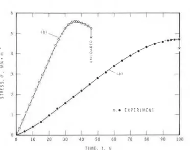
Figure 1 or 3 shows that (iv) the upper yield stress is higher ina truly constant strain rate test than that under the same i. in a conventional
machine. Figure 1 shows that (v) the infinitely stiff closed-loop machine took less time to yield the specimen than did the softer conventional machine. Figures 2 or 3 show that (vi) the stiffer system deformed the specimen less to yield. Thus both strength and ductility depend on the stiffness of the test system. Finally, Fig. 3 shows that (vii) the actual stress-strain diagram in a conventional system (curve (a)) is far from the diagram conventionally
envisioned (curve (c) )
.
COMPARISON BETWEEN THEORY AND EXPERIMENT
Computations for strain were made using Eq. (51, the creep constants given
earlier, and d = 4.5 mm. Although it is better to use At as small as possible,
a comparative study has shown that it is sufficient to divide the stress paths illustrated into about 100 time segments. Theoretical predictions for the two
b 5 c . E 4 Z
-
b J rn",
u LL + 2 L C 1 nu
1 0 20 30 a0 50 6 0 73 SO no i n n T I M E , f , sFig. 1. Stress history of columnar-grained S-2 ice of average grain diameter of 4.5 r m at -lO°C: (a) - nominal strain rate, in, of 3 x s-l in a conventional
system; (b) - constant strain rate, i, of 3 x s-l in a closed-loop system.
I ? 3 : l B . 5 1 s . l 1 4 -
J'
12 - -/*
- ' a ' y * -/
/ -.'
*
0,. E X P E R I M E N T - - T H E O R Y - I I I I n IU 20 3 0 40 s o 6 0 70 so qono
T I M E , t , sFig. 2. Theoretical and experimental strain history corresponding to the results shown in Fig. 1.
tests in Fig. 1 are compared with the experimental results in Figs. 2 and 3. Agreement between theory and experiment is more than acceptable considering the
P,
:
simplicity of the basic equation and the method of calculation, in comparison to* .. .
some recently proposed creep equations (ref. 12), and considering that both
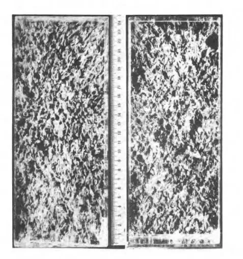
specimens exhibited heavy damage during the tests because of microcracking (Fig. 4
1
I I I I I I I I I t J I - / Q -0
P
z /" - -P
/ -K
- / 4' 0 . - E X P E R I M E N T - I I I I I I I Ix . o . . E X P E R I M E N ~
wd --*X- - T H E O R Y
1
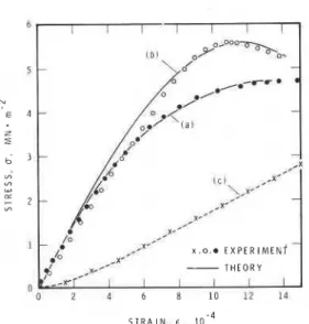
Fig. 3. Theoretical and experimental stress/strain diagrams for columnar-grained
S-2 ice of average grain diameter of 4.5 mm at -lO°C: (a) - nominal strain rate,
in, of 3 x s-1 in a conventional system; (b) - constant strain rate,
t ,
of3 x 10-5 s-l in a closed-loop system. Curve (c) is drawn from o - t data from
curve (a) shown in Fig. 1, following the conventional assumption of a constant strain rate of in.
Observations (i) to (vii) pointed out in the previous section might appear "peculiar to ice" but they are now justified theoretically and hence applicable
..-- -
to any material under similar test conditions where nonlinear viscoelastic I
I
characteristics play an important role.
i
The present discussion will remain incomplete without clarification of another important yet overlooked or, perhaps, generally misunderstood subject. One of the most common engineering practices is to determine elastic modulus from the slope of the linear portion of the stress-strain diagram. There are innumerable engineering textbooks supporting this practice and there is no doubt that the method is sound. The question then arises as to why the modulus determined this way has been found to depend on loading conditions (refs. 13,141 and grain size
(ref. 15).
Figure 3 shows that the experimental stress-strain diagrams (a) and (b) are
- 2
linear up to a stress of about 2 MN-m giving 6.7 G N - ~ - ~ as the average of the
two modulus values. Theoretical predictions are also approximately linear up to the same stress level in both the tests, although they give a slightly higher
- 2
average value of 7.2 GN-m
.
Both experimental and theoretical values agree wellFig. 4. Cracks observed in the entire specimen after unloading: closed-loop test (left); conventional test (right). (Scale in centimetres.)
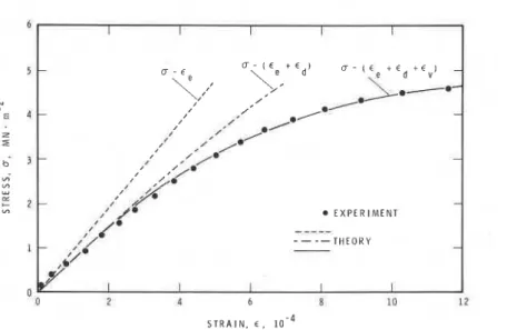
the same strain rate range and temperature. All these values are about 30% lower than Young's modulus of ice (ref. 2). The experimental results do not give any clue as to why they are lower but the theory implies that the lower values are due to the contribution of delayed elastic and viscous components to the total strain, as demonstrated in Fig. 5 for the conventional test, (a) in Fig. 3. Note that the slope in the apparently linear part, in this case, is determined not by pure elasticity but predominantly by a combination of elastic and delayed elastic effects. Contribution of the viscous creep to the total strain increases with the increase in stress and becomes pronounced in this case at stresses greater than about 2 M N - ~ - ~ .
It can be shown using Eq. (5) and the previous analysis that the deviation of the effective moaulw from Young's modulus would depend, in addition to the stress
S T R A I N . 6 .
Fig. 5. Comparison between experimental stress/strain and theoretical stress/ elastic strain, stress/(elastic + delayed elastic strain) and stress/total strain for the conventional test ((a) in Fig. 3). Note that the slope of the initial quasi linear part of the stress/strain curve is determined by elastic and delayed elastic strain.
or strain level, on the rate of loading, temperature, and grain size. Thus the increase in the effective modulus with the increase in strain or stress rate
(ref. 13), frequency (refs. 14,15), and grain size (ref. 15), or with a decrease in temperature (refs. 13,14) observed under dynamic loading conditions, can be
.~ ,
explained and quantified
.
~t (l'~~-'@omologous temperatures, the contribution of I ' inelastic deformation to the totai strain becomes small for low stresses, which explains the success in engineering practice of estimating elastic modulus from stress-strain curves in structural materials at room temperature. This points Out, however, that the established low temperature methods should be examined c ~ ~ i c a l l y ' b e f o r e applying them to high temperature problems.This paper is a contribution from the Division of Building Research, National Research Council of Canada, and is published with the approval of the Director of the Division.
REFERENCES
1 L.N. McCartney and D. McLean, J. Mech. Eng. Sci., 18(1976)39-45.
2 N.K. Sinha, Exp. Mech. 18(1978)464-470. 3 N.K. Sinha, Philos. Mag. A, 40(1979)825-842.
4 H. Conrad, in J.E. Dorn (Ed.), Mechanical Behaviour of ater rials at Elevated Temperatures, McGraw-Hill Book Company Inc., New York, 1961, Ch. 9 , pp.218-269.
5 F. Garofalo, Fundamentals of Creep and Creep-Rupture in Metals, MacMillan Company, New York, 1965.
6 P. Duval and H. LeGac, J. Glaciology, 25(1980)151-157.
7 N.K. Sinha, Presented at 1979 Spring Meeting, Soc. Exp. Stress Anal., San Francisco, May 20-25, 1979. In press, Exp. Mech.
8 N.K. Sinha and R.M.W. Frederking, POAC 79 Proc 5th Int. Conf. Port and Ocean Engineering under Arctic Conditions, Trondheim 13-18 August, 1979, Vol. 1, pp. 708-717.
9 N.K. Sinha, Comparative Study of Some Ice Strength Data. To be presented at IAHR Int. Symp. Ice, Quebec City, Ouebec, July 27-31, 1981.
10 F.K.G. Odqvist, Mathematical Theory of Creep and Creep Rupture, 2nd edn., Clarendon Press, Oxford, 1974.
11 N.K. Sinha, Constant Strain and Stress Rate Compressive Strength of Columnar- Grained Ice. To be published.
12 J.S. Lai and W.N. Findley, (1980) ASME J. Appl. Mech., 47(1980)21-26. 13 A. Traetteberg, L.W. Gold and R. Frederking, Proc. IAHR 3rd Int. Symp. Ice
Problems, Hanover, N.H., August 18-21, 1975, pp. 479-486.
14 T.S. Vinson, T. Chaichanavong and R.L. Czajkowski, ASCE J. Geotech. Eng. Div., 104 (1978) 779-800.
T h i s p u b l i c a t i o n i e being d i s t r i b u t e d b y the Division of n u l l d i n g R e e c a r c h of t h e N a t i o n a l R e e e a r c h Council of Canada. I t s h o u l d not b e r e p r o d u c e d in whole o r in p a r t without p e r m i s s i o n of the o r i g i n a l p u b l i s h e r . T h e Di- v i s i o n would b e g l a d t o b e of a s s i s t a n c e i n obtaining s u c h p e r m i s s i o n .
P u b l i c a t i o n s of t h e Division m a y be obtained by m a i l - ing the a p p r o p r i a t e r e m i t t a n c e ( a Bank, E x p r e s s , o r P o e t Office M o n e y O r d e r , o r a cheque, m a d e p a y a b l e t o t h e R e c e i v e r G e n e r a l of Canada, c r e d i t NRC) t o t h e N a t i o n a l R e s e a r c h Council of Canada, Ottawa. K I A O R 6 . S t a m p s a r e not a c c e p t a b l e .
A l i s t of a l l p u b l i c a t i o n s of the Division i s a v a i l a b l e and m a y b e obtained f r o m the P u b l i c a t i o n s S e c Lion. Division of Building R e s e a r c h , N a t i o n a l R e s e a r c h C o u n c i l of C a n a d a , O t t a w a . KIA 0R6.