HAL Id: inria-00582506
https://hal.inria.fr/inria-00582506
Submitted on 15 Jun 2011
HAL is a multi-disciplinary open access
archive for the deposit and dissemination of
sci-entific research documents, whether they are
pub-lished or not. The documents may come from
teaching and research institutions in France or
abroad, or from public or private research centers.
L’archive ouverte pluridisciplinaire HAL, est
destinée au dépôt et à la diffusion de documents
scientifiques de niveau recherche, publiés ou non,
émanant des établissements d’enseignement et de
recherche français ou étrangers, des laboratoires
publics ou privés.
An MDE-based approach for solving configuration
problems: An application to the Eclipse platform
Guillaume Doux, Patrick Albert, Gabriel Barbier, Jordi Cabot, Marcos
Didonet del Fabro, Scott Lee
To cite this version:
Guillaume Doux, Patrick Albert, Gabriel Barbier, Jordi Cabot, Marcos Didonet del Fabro, et al..
An MDE-based approach for solving configuration problems: An application to the Eclipse platform.
ECMFA 2011 - Seventh European Conference on Modelling Foundations and Applications, Jun 2011,
Birmingham, United Kingdom. �inria-00582506�
An MDE-based approach for solving configuration
problems: An application to the Eclipse platform
Guillaume Doux 1, Patrick Albert 2, Gabriel Barbier 3, Jordi Cabot 1, Marcos Didonet
Del Fabro 4, Scott Uk-Jin Lee 5 1 AtlanMod, INRIA & EMN, Nantes
2 IBM France, Paris 3 Mia-software, Nantes 4 Universidade Federal do Paraná
5 CEA, LIST, Gif-sur-Yvette
{Guillaume.Doux , Jordi.Cabot}@inria.fr, AlbertPa@fr.ibm.com, gbarbier@mia-software.com, marcos.ddf@inf.ufpr.br,
Scott.Lee@cea.fr
Abstract. – Most of us have experienced configuration issues when installing
new software applications. Finding the right configuration is often a challenging task since we need to deal with many dependencies between plug-ins, components, libraries, packages, etc; sometimes even regarding specific versions of the involved artefacts. Right now, most configuration engines are adhoc tools designed for specific configuration scenarios. This makes their reuse in different contexts very difficult. In this paper we report on our experience in following a MDE-based approach to solve configuration problems. In our approach, the configuration problem is represented as a model that abstracts all irrelevant technological details and facilitates the use of generic (constraint) solvers to find optimal solutions. This approach has been applied by an industrial partner to the management of plug-ins in the Eclipse framework, a big issue for all the technology providers that distribute Eclipse-based tools.
Keywords: Configuration, MDE, Eclipse, Plug-in, Cartography
1
Introduction
Complex software systems are built by assembling components (components in a broad sense, i.e. COTS, libraries, plug-ins,…) coming from different repositories. This simplifies the development of the system but inevitably introduces an additional complexity dimension due to the need of managing these components. Each component can evolve independently and new releases can introduce/break dependencies with other components.
In particular, this is becoming a huge problem in the Eclipse community where new tools are built on top of several other plug-ins already available in the platform, many times requiring a specific version of the plug-ins. Therefore, releasing a new Eclipse tool implies a precise build definition for the tool that must be continuously evolved.
Therefore, technology providers commercializing Eclipse tools are looking for solutions that help them to automate and optimize the build definitions for their tools so that end-users do not need to suffer all these configuration problems. Right now, this very costly and time-consuming task requires a dedicated engineer in the provider company. This engineer needs to manually provide all the information regarding the tool dependencies, the plug-ins that can satisfy those dependencies and also the repositories where the plug-ins are available. Moreover, once everything is defined, the generated build definition needs to be empirically tested. Clearly, for non-trivial projects, this process does not scale.
In this paper, we propose to overcome this situation by means of using Model Driven Engineering and Constraint Programming techniques to automate the generation of build definitions. This work has been done in collaboration with two industrial partners: Mia-Software1
This paper is structured as follows. Section
, a well-known technology provider in the Eclipse community that leads several Eclipse projects and IBM that has contributed its expertise in commercial constraint programming tools.
2 discusses the motivations of our solution in an industrial environment. Section 3 presents the overall approach used to manage our Eclipse plug-ins configuration problem. Section 4 is focused on the management of the configuration as a Constraint Satisfaction Problem (CSP) whereas Section 5 describes the decision tree approach for finding configurations, and Section 6 illustrates the tool used to visualize the configurations. Section 7 presents the implementation, a comparison between the resolution approach described and the lessons learnt. Section 8 focuses on the related works and Section 9 concludes this study.
2
Motivation: Industrial Challenge
This work has been motivated by the need of Mia-Software to configure and control build definitions for its tools and to be able to update such definitions during the tool lifecycle.
A second (and more complex) requirement is to be able to tailor build definitions to different scenarios, such as targeting the minimal subset of elements to run the application in a headless mode (using scripts on a server), or selecting only non-GPL component to allow integration in proprietary applications.
The results of this work are being integrated in the MoDisco2 and EMF Facet3
As an example, the MoDisco Eclipse project alone contains 94 plug-ins (without the 30 test ins) and depends directly or indirectly on around 920 additional plug-ins. For the time being, the MoDisco project has a dedicated plug-in to configure the build definition. This plug-in contains more than ten types of files to do so (ant files, xml files, properties files, cspec files, cquery files, mspec files, rmap files, xsl files, sh Eclipse projects and in the custom developments the company builds internally for its clients.
1 Mia-Software: http://www.mia-software.com/
2 The MoDisco project: http://www.eclipse.org/MoDisco/
files and txt files). To be able to maintain all of these artifacts and to reproduce in a server environment the behavior of a development environment, a dedicated engineer is now assigned to the task. To initially configure the build definition one full month of the engineer was required. Unfortunately, due the continuous evolution of the Eclipse platform this is not just a one-time effort. Every time there are new relevant plug-in versions or a new release of the Eclipse platform available, two or three additional days are spent in adapting the configuration (e.g. to update the locations of update sites for dependencies). Furthermore, the correctness of the process cannot be detected until the application is rebuilt again.
Therefore, MoDisco is clearly a tool that could benefit from the results of our work. It is worth to note that this kind of complex dependencies scenario is not the exception but the norm and thus, any tool that improves the current state of the art could have a real impact on current industrial practices of Mia-Software and similar technology providers.
3
Overall approach
This section gives an overview of our Model Driven approach for solving Eclipse plug-ins configuration problems. Adopting an MDE approach has several advantages. First, it provides a homogeneous representation for all the technologies involved in the solution. Secondly, it allows designers to deal with the problem at a higher-abstraction level where some irrelevant details are omitted. And finally, the own Eclipse platform is moving more and more towards the adoption of model-based solutions (as the b3 Eclipse models used to define build generations) so an MDE approach perfectly fits in this scenario.
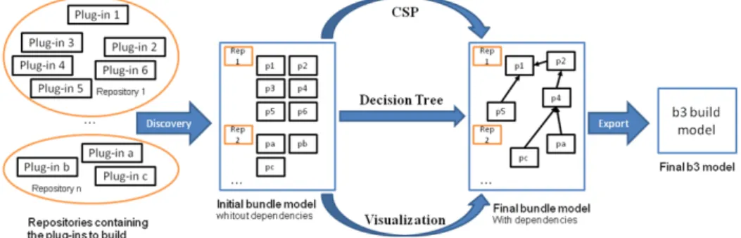
Our approach follows a three step process (see Fig. 1).
Figure 1 - Overview of the Eclipse plug-ins build generation process
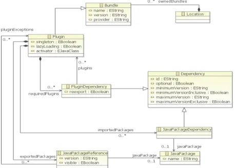
In the first step, a discovery phase allows the designer to express the requirements for the tool/component/plug-in she wants to build and the possible locations (i.e. repositories) where to find plug-ins that satisfy those requirements. The information concerning these plug-ins such as the dependencies they need, the name, the version or every other useful information is stored in a plug-in model conforming to the
metamodel presented in Figure 2. This metamodel allows the representation of the different elements needed for the plug-ins configuration representation. The main entity of this metamodel is the Plugin class whereas the main relationship between plug-ins is represented by the PluginDependency class. This class allows linking the plug-ins according to their dependencies. A second set of entities and relations is expressed with the JavaPackage and the JavaPackageDependencies classes. A
JavaPackageDependency element allows the representation of the relation between a Plugin element and the imported JavaPackage elements. At this stage, we just have
the “raw data”, i.e. we have the candidate plug-ins but not yet the selected configuration.
This is done in the second step: a possible combination of the candidate plug-ins (i.e. respecting all their dependencies) is created either manually (visualization option), interactively (decision tree option) or automatically (constraint programming option). When several configurations are possible, the final selection can be driven by additional search criteria like newest versions of the plug-ins (default option), license or cost. We propose these three different ways to obtain a configuration since each one offers a different trade-off as explained later on. As a result of this step we get a refined plug-in model with information from the selected configuration for the build generation.
Figure 2 - Metamodel to represent the plug-ins
The last step is the generation of the final configuration file from the refined plug-in model. In our case the configuration will be expressed as a b3 model but it could easily be expressed as a Maven4 file or Ant5
4The Maven project, http://maven.apache.org/
the development of a new generation of Eclipse technology to help building and assembling software. It proposes an approach using model driven engineering to represent the different artifacts that are relevant for building applications. More specifically, b3 proposes a metamodel to represent all of artifacts needed for the build, and execution support for these build models. Therefore in our approach the generation of the final configuration file is realized using model to model (or model to text in the case of Maven and ANT) transformations.
4
Configuration as a CSP
Constraint Programming [8] is a declarative problem solving paradigm where the programming process is limited to the definition of the set of requirements (constraints). A constraint solver is in charge of finding a solution that satisfies the requirements. Problems addressed by Constraint Programming are called constraint satisfaction problems (CSPs). A CSP is represented by the tuple CSP = <V,D,C> where V denotes the finite set of variables of the CSP, D the set of domains, one for each variable, and C the set of constraints over the variables. A solution to a CSP is an assignment of values to variables that satisfies all constraints, with each value within the domain of the corresponding variable.
We can represent the problem of configuration of Eclipse plug-ins as a CSP. This solution is a practical instantiation of the approach called Model Search [4].
The problem can be stated as follows: given a set of partially-connected Eclipse-plug-ins and a set of constraints that must be satisfied, find one (or the optimal, according to a given property) valid and executable build distribution. The constraints may be of different nature. For instance, defining version dependencies between the plug-ins, or specifying one desired vendor.
The constraints are written using OCL++. OCL++ is an adaptation of OCL (Object Constraint Language) [6]. OCL++ simplifies OCL for writing CSP problems. For instance, it enables writing multi-class invariants, which is a common construct in CSP problems. It also enables writing optimization functions.
More specifically, the re-expression of a configuration Eclipse problem in terms of a CSP is implemented as a chain of transformation operations over the initial plug-in model. Since Existing CSP solvers cannot directly read EMF models and OCL++ constraints as input, we need to translate the input artifacts into the CP language supported by the constraint solver of the ILOG OPL-CPLEX development bundle [7] engine, which is OPL (Optimization Programming Language). The OPL engine enables adding optimization functions, i.e., to find the best solution given an optimization criterion. The main steps of the process are:
1. Transformation of the Eclipse plug-in metamodel and the constraints into the OPL language.
2. Transformation of the input model into the OPL data format. The separation of the input model and metamodels into two transformations enables having
5The ANT project, http://ant.apache.org/
independence between the problem specification (metamodels + constraints) and the input models with the initial data to start the CP process.
3. Execution of the CSP engine. This operation is called model search. During this phase the input model is extended with the solutions found by the engine. However, the result produced by the CP engine is expressed as sets of integers, String and floats (the OPL output format).
4. Transformation of the output into a model conforming to the Eclipse plug-ins metamodel.
To facilitate the execution of these different steps a predefined script in charge of chaining the transformations is provided.
This approach combines the benefits of CSP with the advantages of expressing the problem at the model level (e.g. writing the constraints in OCL++). Moreover, the transformation chain makes the CP solver transparent to the user who provides and receives models as input/output of the process. Clearly, it would be even better that the transformation from the models to the CSP included an additional intermediate step where the CSP is expressed as instance of a solver-independent CSP metamodel. This would facilitate the utilization of different CSP solvers.
5
Decision Tree
Decision Trees is a strategy used in the field of Software Product Line (SPL) to illustrate all possible product configurations in terms of decisions on variations. It enables interactive configurations where user selects an appropriate decision for each variation to configure a particular product. The main benefits of utilizing decision tree in configuration are the clear presentation of all possible configurations and the ability to customize the configuration by allowing each decision made on variation to be based on different criteria. As only valid configurations are proposed in the decision tree, the build engineer work becomes simpler and safer using this approach. On the other hand, the strategy main limitation, compared to the CSP one, appears when there are a large number of choice criteria involving an important number of choices for the engineer. In that case, it can become difficult to manage efficiently a big configuration.
In order to take advantage of these benefits, we adapt the concept of decision tree and Sequoia, a UML based SPL tool embedded in Papyrus, to our configuration challenge. The main difference with the CSP implementation is in the generation of several build configurations instead of only one. This characteristic involves some user interactions for the final configuration choice. The process of Eclipse plug-ins configuration with Sequoia consists of different steps as described below:
1. Construction of the initial bundle model in UML – The initial bundle model obtained from the discovery phase must be transformed into a UML model since Sequoia is a UML specific tool. As in the Eclipse plug-ins problem, several versions of the same plug-in can exist, and thus, a way to identify plug-ins conforming to the same unique plug-in definition is needed. The plug-in definition can be seen as a “formal” plug-in having several “instance” plug-ins, corresponding to the different available version of this plug-in. In the
transformation, formal ins are defined as classes to type all the instance ins of the model. Then, in locations are defined as packages to group all plug-ins in the same location. Plug-in classes include useful metadata such as version, price and license. Each possible instantiation of the plug-in (i.e. different versions or vendors for the plug-in) instantiate these classes with the appropriate information to be considered during the configuration. Dependencies for a plug-in are represented as a dependency relationship from the depender plug-in to the dependee plug-in class.
2. Extraction of dependency constraints – Once the initial bundle model is constructed in UML, the dependency constraints are extracted following the specific profile defined in Sequoia. In addition, the extraction process can also accommodate the dependencies with constraints on criteria by allocating all the instances of the class that meet the constraints. For example, a dependency from the plug-in instance 'a' to a plug-in class 'B' with the constraint limiting the version of 'B' to be less than 3.0 will be converted into the set of dependencies from 'a' to 'b' with version 1.0 and 'b' with version 2.0.
3. Computation of dependency constraints – Once all dependencies are expressed as constraints, Sequoia uses the formal verification tool Alloy Analyzer [8] to produce all feasible configurations. The result of the calculation represents all possible configuration of the plug-ins computed based on their dependencies and represented in a textual format.
4. Decision tree creation – After the computation, the extracted dependency constraints are analyzed against the textual result of the calculation to construct a decision tree with decision nodes representing dependency constraints and its resolution edges representing all the configuration decisions that satisfy that dependency. In addition, values of various plug-in criteria are calculated and indicated for each resolution edge. Users can use these values to make more informed choices when interacting with the tree.
5. Transformation of decision tree into final bundle model – Finally, an Eclipse plug-in configuration interactively generated from the decision tree is transformed into a final bundle model.
6
Visualization
The visualization mechanism allows quickly checking if the obtained configuration fits the user needs and, if several possible configurations have been produced, the user can choose the one he prefers from the visualizations. For simple configuration problems, the visualization of the plug-ins suffices to manually define the optimal configuration. Nevertheless, this kind of approach cannot be used to manage configurations involving an important number of elements, as the generated graph becomes too complex to be understandable. As an example, a visualization of an initial bundle model is shown Figure 3.
This visualization component relies on the cartography plug-in Portolan6
To visualize plug-in data we just need to link the plug-in metamodel with the generic cartography metamodel provided with Portolan and, optionally, configure the view definitions that filter the input data and specify how this data will be visualized. The relationship between the plug-in and the cartography metamodels is done by defining the plug-in metaclasses as subclasses of the two main cartography metaclasses (entity and relationship). Once this is done, transforming data conforming to the plug-in metamodel to data conforming to the cartography metamodel is trivial (it is mainly a simple copy transformation).
. Integration with Portolan is easy since Portolan uses a model driven approach for the cartography analysis and visualization.
Figure 3 - Screenshot of the visualization tool
7
Implementation and preliminary results
The MDE-based approach presented here for solving Eclipse configuration problems has been implemented as an Eclipse set of plug-ins that provide the discovery of available plug-ins, the computation of possible dependencies, their visualization and the final build generation services. These functionalities are briefly presented in this section.
The discovery functionality is implemented as an Eclipse file creation wizard. This wizard proposes the creation of a model which is conforming to our metamodel dedicated to the Eclipse bundles representation (presented in Figure 2). To this aim, it allows selecting several plug-ins present in the workspace and then choosing the update sites that have to be considered when discovering candidate plug-ins for the bundle model.
The connection with the configuration engines (both the CSP and the decision tree versions) has been implemented as described in their respective sections. Also, as indicated, the visualization service is implemented using a model driven cartography
tool called Portolan. A specific extension of Portolan has been designed for this study to be able to visualize configuration models.
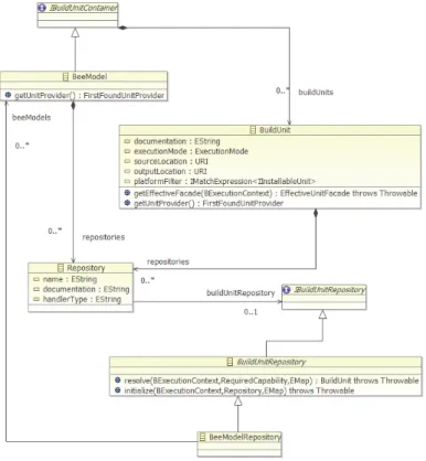
The build generation functionality takes the feedback from the previous configuration plug-ins and generates a b3 model representing the selected configuration. This is mainly done by executing an ATL transformation between the internal model conforming to the plug-in metamodel (presented in Figure 2) and the final b3 model conforming to the b3 metamodel. This b3 model will be processed by the b3 engine to drive the build generation (by retrieving the needed plug-ins and launching the different steps of the application build). An excerpt of the b3 metamodel (Figure 4) presents the main elements used for the build generation. The
BeeModel class represents the build model root; this class contains references to the BuildUnit and Repository elements used. In the model, a BuildUnit represents
something to build with b3, in our case it will be a bundle (in the general case, it can also be a library or any other kind of component). The repositories reference of
BuildUnit allows knowing which repositories can be used for the build unit’s
resolution. The BuildUnitRepository class allows the declaration of a build unit repository location in b3. A specific type of it is represented by the
BeeModelRepository class; this repository declaration refers to the BeeModel to use
for building the components contained in the repository.
Of course, other alternative implementations (e.g. Maven, ANT) of this service could easily be provided using the own Eclipse extension mechanisms.
After the initial set of experiments we have been able to validate that all three strategies (CSP, decision tress and purely visualization) can be used to solve the configuration problem. Each one has its own trade-offs and is best suited to address a specific kind of configuration problem. This is exactly the reason why we decided to keep the three of them in the framework without clearly favoring any of them.
The CSP-based approach is the best option when looking for a completely automatic solution. It is also recommended when looking for a single solution according to a specific criteria and when dealing with very complex problems (on which human interaction is not feasible).
Decision trees is an intermediate solution. It does most part of the job automatically (calculating all possible solutions) but still gives some flexibility to the designer to influence the final choice.
Visualization per se is only useful for simple solutions as an aid for the designer but it is a good complement to the other two as a visualization tool for the computer-generated solutions.
Besides this, the realization of this project has also shown the benefits of MDE when used as a tool for the unification of heterogeneous domain, such as the Eclipse plug-ins and the constraint programming domains. By expressing both domains (i.e. technical spaces) as models, we obtain a homogeneous representation that facilitates the transformation/communication between them.
Nevertheless, these first experiments have also pointed out some challenges that need to be addressed in the future. Reasoning tools usually suffer from scalability problems and our scenario is not an exception. Sometimes user interaction is required just because the search space is too big to get an answer from the solver in a reasonable time and the designer must help to reduce it by providing additional constraints to limit the search.
Also, our approach suffers from the lack of standards in the constraint programming domain. Even if part of the transformation chain is generic, the last steps are solver-dependent and need to be reimplemented if the development team decides to use a different solver in the future.
We are now working in both aspects. For instance, regarding the second one we are adopting the idea of a CSP solver-independent metamodel that abstracts until the last step the specificities of the solver to use. The translation of the configuration information present in a solver independent model into solver specific models becomes easy to specify using model transformations and should permit to choose the most appropriated solver for the configuration resolution.
8
Related Work
An alternative solution for plug-in management in Eclipse is called p2 [2]. This solution proposes to use the metadata of the plug-ins to create a set of constraints that are solved with the SAT solver SAT4j7
7 Sat4j website:
. In this approach there is no explicit modeling
of the problem so designers cannot define additional constraints about the desired characteristics of the solution (e.g. to get an optimal configuration). Moreover, since the translation is adhoc cannot be reused. Besides this, this approach only focuses on one of the alternative strategies we have explored.
Another interesting proposal is [1]. It proposes to use a model driven approach to represent the configuration and available packages for FOSS distributions. These models are then used to predict the effect of changes on the installed package base (e.g. upgrades) on the system configuration. As our own work, this approach brings the advantages of working at a higher abstraction level when compared with approaches that rely on a direct manipulation of the available metadata. Nevertheless, our approach is able to deal with a more general problem since we are able to create the entire configuration and not only simulate/predict what would happen if something changes.
The topic of translating models into other formalisms for an automatic analysis has been explored in several previous approaches (e.g. [10-13]) but they mostly focus on specific kinds of UML diagrams. Some of these techniques could be adapted to our configuration models and integrated in our framework to provide additional analysis capabilities.
9
Conclusions
This paper reports a collaboration between industrial and research partners to solve configuration problems faced by technology providers using a combination of model-driven engineering and constraint programming techniques.
We have focused on the specific configuration problems for tools developed on top of the Eclipse platform that need to manage and solve a lot of plug-in dependencies. This use case has been provided by Mia-software, a software editor specialized in the application Model Driven approaches for the software lifecycle industrialization with plenty of experience in the development of Eclipse projects.
As further work, we plan to generalize our framework to deal with configuration problems in other domains. The core of the approach can be easily reused but specific metamodels (e.g. Linux packages metamodel for Linux distributions configuration) need to be developed for each specific application domain.
Acknowledgement:
This work has been partially funded by ANR IdM++ project.References
1. A. Cicchetti, D. Di Ruscio, P. Pelliccione, A. Pierantonio and S. Zacchiroli. Towards a model driven approach to upgrade complex software systems. In Proceedings of ENASE 2009 (4th international conference on Evaluation of Novel Aspects to Software
2. D. Le Berre and P. Rapicault. Dependency management for the eclipse ecosystem. In Proceedings of IWOCE2009 (International workshop on Open Component Ecosystems) (2009).
3. O. Gruber, B.J. Hargrave, J. McAffer, P. Rappicault, T. Watson. The eclipse 3.0 platform: Adopting osgi technology. IBM Systems Journal, 44(2) (2005).
4. M. Kleiner, M.Didonet Del Fabro, P.Albert: Model Search: Formalizing and Automating Constraint Solving in MDE Platforms. In proceedings of ECMFA 2010: 173-188 (6th European conference on Modelling Foundations and Applications) (2010)
5. EMF. Eclipse Modeling Project. Reference site; http://www.eclipse.org/emf 6. OCL 2.0 specification: http://www.omg.org/spec/OCL/2.0/, 2008
7. ILOG OPL-CPLEX development bundle.
http://www-01.ibm.com/software/integration/optimization/cplex-dev-bundles/, Jan 2010. 8. D. Jackson. Alloy: a lightweight object modelling notation. ACM Transactions on
Software Engineering and Methodology, 11(2):256–290, 2002
9. Apt, Kristoph R.: Principle of Constraint Programming. Cambridge University Press (2003)
10. A. D. Brucker and B.Wolff. The HOL-OCL book. Technical Report 525, ETH Zurich, 2006
11. J. Cabot, R. Clarisó, D. Riera: UMLtoCSP: a tool for the formal verification of UML/OCL models using constraint programming.ASE 2007:547-548
12. R. V. D. Straeten, T. Mens, J. Simmonds, and V. Jonckers. Using description logic to maintain consistency between. UML models. In Proc. of UML’03., volume 2863 of LNCS, pages 326–340. Springer, 2003.
13. K. Anastasakis, B. Bordbar, G. Georg, and I. Ray.Uml2alloy: A challenging model transformation. In ACM/IEEE 10th International Conference on Model Driven Engineering Languages and Systems, pages 436–450, 2007