HAL Id: tel-03080574
https://tel.archives-ouvertes.fr/tel-03080574
Submitted on 17 Dec 2020HAL is a multi-disciplinary open access archive for the deposit and dissemination of sci-entific research documents, whether they are pub-lished or not. The documents may come from teaching and research institutions in France or abroad, or from public or private research centers.
L’archive ouverte pluridisciplinaire HAL, est destinée au dépôt et à la diffusion de documents scientifiques de niveau recherche, publiés ou non, émanant des établissements d’enseignement et de recherche français ou étrangers, des laboratoires publics ou privés.
Predictive energy management for fuel cell hybrid
electric vehicle
Yang Zhou
To cite this version:
Yang Zhou. Predictive energy management for fuel cell hybrid electric vehicle. Other. Université Bourgogne Franche-Comté, 2020. English. �NNT : 2020UBFCA020�. �tel-03080574�
THÈSE DE DOCTORAT DE L’ETABLISSEMENT UNIVERSITÉ BOURGOGNE FRANCHE-COMTÉ
PRÉPARÉE A L’UNIVERSITÉ DE TECHNOLOGIE DE BELFORT-MONTBÉLIARD
Ecole doctorale n°37
Sciences Pour l’Ingénieur et Microtechniques
Doctorat de Génie électrique
Par
Yang ZHOU
Gestion de l'énergie prédictive appliquée aux véhicules hybrides pile à combustible
Thèse présentée et soutenue à Belfort, le 12/11/2020
Composition du Jury :
M. Rachid Outbib Professeur à l’Université d'Aix-Marseille Président M. Olivier Sename Professeur à l’Institut Polytechnique de Grenoble Rapporteur Mme. Florence Ossart Professeure à Sorbonne Université Rapportrice M. Ali Sari Professeur à Université Claude Bernard Lyon 1 Examinateur M. Simon Morando Spécialiste diagnostique et pronostique de PEMFC chez Symbio Examinateur M. Marco Sorrentino Maitre de conférences à l'Université de Salerno Examinateur Mme. Marie-Cécile Péra Professeure à l’Université de Franche-Comté Directeur de thèse M. Alexandre Ravey Maitre de conférences à l’Université de Technologie de Belfort-Montbéliard Codirecteur de thèse
PH.D. THESIS OF THE UNIVERSITY BOURGOGNE FRANCHE-COMTÉ
PREPARED AT THE UNIVERSITY OF TECHNOLOGY OF BELFORT-MONTBÉLIARD
Doctoral School n°37
Engineering Sciences and Microtechnologies
Doctor of Philosophy (Ph.D.) in Electrical Engineering
by
Yang ZHOU
Predictive energy management for fuel cell hybrid electric vehicle
Thesis presented and defended in Belfort, on 12/11/2020
Composition of Jury:
M. Rachid Outbib Professor at Aix-Marseilles University President M. Olivier Sename Professor at Grenoble Institute of Technology Reviewer Mme. Florence Ossart Professor at Sorbonne University Reviewer M. Ali Sari Professor at University Claude Bernard Lyon 1 Examiner M. Simon Morando PEMFC diagnosis and prognosis specialist at Symbio corporation Examiner M. Marco Sorrentino Associate Professor at University of Salerno Examiner Mme. Marie-Cécile Péra Professor at University of Franche-Comté Supervisor M. Alexandre Ravey Associate professor at University of Technology of Belfort-Montbéliard Co-supervisor
Titre: Gestion de l'énergie prédictive appliquée aux véhicules hybrides pile à combustible
Mots clés : véhicule électrique hybride, gestion de l'énergie, pile à combustible
Résumé : Les véhicules électriques hybrides à pile à combustible ont été largement considérés comme la substitution prometteuse par rapport aux véhicules traditionnels à moteur à combustion interne. Pour réduire les coûts d'exploitation des véhicules, une solution pratique au stade actuel consiste à utiliser efficacement et sainement les systèmes de propulsion hybrides. Une telle tâche peut être remplie via des stratégies de gestion d'énergie fiables, qui coordonnent les sorties de plusieurs sources d'énergie pour satisfaire la demande de puissance des véhicules.
Dans un tel contexte, cette thèse vise à concevoir des stratégies de gestion intelligente de l'énergie pour les véhicules électriques hybrides à pile à combustible. Par rapport aux stratégies de contrôle existantes, cette thèse se concentre particulièrement sur la possibilité de combiner les informations de conduite prévues avec le cadre de contrôle optimal en temps réel.
Plusieurs techniques de prédiction de conduite sont développées pour estimer les conditions de conduite à venir, comme la vitesse du véhicule, la référence de l’état de charge de la batterie et les informations sur le modèle de conduite. Ensuite, la model predictive control est sélectionnée pour la prise de décision en temps réel, car elle est capable de gérer les systèmes contraints variant dans le temps et est pratique pour l'intégration des informations prédictives de pilotage. Sur la base des résultats prévus et model predictive control, plusieurs stratégies de gestion prédictive de l'énergie sont établies, visant à économiser la consommation d'hydrogène et à améliorer la durabilité des piles à combustible par rapport aux stratégies de référence.
La simulation hors ligne et les tests logiciels en boucle ont vérifié la fonctionnalité et l'adéquation en temps réel des stratégies proposées.
Title: Predictive energy management for fuel cell hybrid electric vehicle
Keywords: hybrid electric vehicle, energy management, fuel cells
Abstract: Fuel cell electric vehicles have been widely deemed as the promising substitution against traditional internal combustion engine-based vehicles. To reduce the vehicular operating costs, a practical solution at current stage is to efficiently and healthily use the hybrid propulsion systems. Such task can be fulfilled via reliable energy management strategies, which coordinate the outputs of multiple energy sources to satisfy the vehicular power request.
In such context, this PhD thesis intends to devise intelligent energy management strategies for fuel cell hybrid electric vehicles. Compared to existing control strategies, this thesis especially focuses on the possibility of combining the forecasted driving information with the real-time optimal control framework.
Several driving prediction techniques are developed to estimate the upcoming driving conditions, like the vehicle’s speed, battery state-of-charge reference and driving pattern information. Thereafter, model predictive control is selected for real-time decision-making, since it is capable of handling the time-varying constrained systems and is convenient for the integration of driving predictive information. Based on the forecasted results and model predictive control, several predictive energy management strategies are established, aiming at saving hydrogen consumption and enhancing fuel cell durability versus benchmark strategies.
Both offline simulation and software-in-the-loop testing have verified the functionality and real-time suitability of the proposed strategies.
Université Bourgogne Franche-Comté 32, avenue de l’Observatoire
i
Acknowledgement
First of all, I am very grateful to Prof. Olivier Sename and Prof. Florence Ossart for their agreements in review of this thesis, despite their very busy schedule. The constructive feedbacks they have given are of great help in improving the quality of this thesis. Besides, I also want to thank Prof. Rachid Outbib, Prof. Ali Sari, Dr. Marco Sorrentino and Dr. Simon Morando for their kindly assistances in preparation for thesis defense.
I would like to express my special appreciations to my supervisor and co-supervisor, Prof. Marie-Cécile Péra and Dr. Alexandre Ravey, respectively. I still remember that, at the beginning of my PhD study, I know nothing about fuel cells, hybrid electric vehicles and optimization, let alone how to initiate innovative researches or how to write high-quality scientific articles. Throughout my three-year PhD study, it is their constant support and patient guidance that encourage me to find the truth in scientific researches. They set up themselves as the real models to show me how to become an independent and professional researcher. Moreover, the critical thoughts and insightful suggestions they have proposed have generated profound impacts not only on this PhD thesis but also on my future career. It is my great privilege to work with them during the last three years.
I want to specially thank Prof. Fei Gao for his selfless help and constant support during my PhD study. His motivation and perseverance towards scientific researches greatly inspire me during the past three years. Moreover, I would like to express my sincere appreciations to Prof. Ruiqing Ma and Prof. Yigeng Huangfu from Northwestern Polytechnical University for their guidance and suggestions towards my future scientific career.
Wherever you go, friends are always here. I would like to convey my sincere appreciations to my friends: Mr. Weizhu QIAN, Mr. Shengrong ZHUO, Mr. Hongjian WU, Mr. Shiming XIE, Miss Bingcong JIAN, Miss Linrunjia LIU, Miss Shuangshuang Meng, Miss Yue ZHOU, Dr. Rui MA, Dr. Chen LIU, Dr. Hao BAI, Dr. Hanqing WANG, Dr. Hailong WU, Dr. Yu WU, Dr. Huan LI, Dr. Jian ZHANG, Dr. Bei LI, Dr. Meiling Yue, Dr. Dan ZHU, Dr. Suyao Kong, Mr. Zhiguang HUA, Mr. Xinyang HAO, Mr. Tianhong WANG, Mr. Qian LI and many other friends in France and China. Besides, I would also like to thank my dear colleagues in UTBM: Dr. Berk Celik, Dr. Salah Soued and Dr. Loic Vichard. It takes time from resisting, accepting, towards slowly falling in love with a place. The people and endless memories encountered here are the most effective catalyst for this process. Three-year is enough to ferment my emotions. Thank you, Belfort, for always embracing me and being my second hometown. Family accompany is my biggest treasure all the way. My deepest love goes to my families.
Finally, the financial support from China Scholarship Council (CSC) during my PhD study is sincerely appreciated.
iii
Table of contents
General Introduction ... 1
Chapter 1. Introduction ... 3
1.1. Fuel cell hybrid electric vehicles ... 3
1.2. Energy management strategy for fuel cell/battery-based HEV ... 8
1.2.1 Characteristics of powertrain energy sources ... 8
1.2.2. Research progress of energy management strategies ... 12
1.3. Driving prediction techniques ... 15
1.3.1. Relationship between driving prediction techniques and predictive energy management strategies ... 15
1.3.2. Forecast objectives and algorithms ... 16
1.4. PhD project objectives ... 25
1.4.1. Knowledge gap in existing studies ... 25
1.4.2. Innovation and contribution ... 26
1.5. Publication List ... 28
References ... 29
Chapter 2. Comparative study on energy management strategy for fuel cell electric vehicles .... 35
2.1. Introduction ... 35
2.2. State-of-the-art review on energy management strategies ... 36
2.2.1. Rule-based strategies ... 37
2.2.2. Global optimization-based strategies ... 42
2.2.3. Real-time optimization-based strategies ... 46
2.2.4. Comparison of different energy management strategies ... 51
2.3. Model predictive control-based energy management strategies ... 53
2.3.1. Model predictive control: brief introduction to theory ... 53
2.3.2. Model predictive control: application in vehicular energy management field ... 54
2.3.3. Challenges for MPC-based EMS in vehicular applications ... 57
2.4. Conclusion ... 57
References ... 58
Chapter 3. Development of driving prediction techniques ... 65
3.1. Introduction ... 65
3.2. Speed forecasting techniques ... 66
3.2.1. Benchmark speed predictors... 66
3.2.2. Layer recurrent neural network speed predictor ... 69
iv
3.2.4. Fuzzy C-means clustering enhanced Markov speed predictor ... 91
3.3. Battery energy depletion planning approaches ... 99
3.3.1. Benchmark SoC reference estimation approach ... 100
3.3.2. Integrable adaptive SoC reference estimation approach ... 100
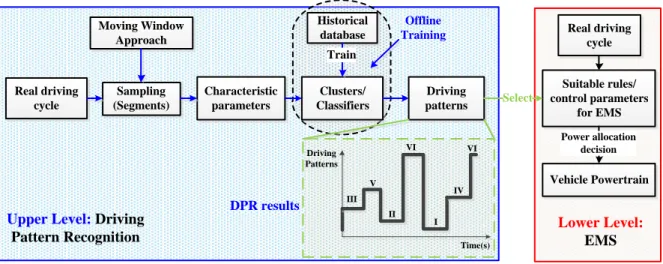
3.4. Driving pattern recognition techniques ... 103
3.4.1. Working principle of the Markov Chain based DPR approach ... 103
3.4.2. Conventional and self-learning Markov model ... 103
3.4.3. Driving pattern recognition performance validation ... 113
3.5. Conclusion ... 120
References ... 121
Chapter 4. Integrated predictive energy management strategies for fuel cell hybrid electric vehicles... 123
4.1. Introduction ... 123
4.2. Powertrain architecture and system modelling ... 124
4.2.1. Vehicle model and powertrain architecture ... 124
4.2.2. Quasistatic fuel cell model ... 126
4.2.3. Battery model ... 131
4.2.4. Electric machine model ... 133
4.3. Multi-mode predictive energy management strategy ... 134
4.3.1. Multi-mode model predictive controller... 135
4.3.2. Energy management strategy performance evaluation ... 144
4.4. Online-learning enhanced predictive energy management strategy ... 149
4.4.1. Power allocation using model predictive control ... 150
4.4.2. Performance verification of predictive energy management strategy ... 152
4.5. Integrated predictive energy management strategy for mail-delivery vehicle ... 163
4.5.1. Energy distribution using model predictive control ... 164
4.5.2. Evaluation on predictive energy management strategy ... 166
4.6. Vehicle’s operating cost analysis under different sizing configurations ... 175
4.6.1. Vehicular operation cost extraction ... 175
4.6.2. Vehicle’s operation costs under different sizing configurations ... 177
4.6.3. Summary of impacts on vehicle’s performance by sizing discrepancies ... 181
4.7. Conclusion ... 182
References ... 182
Chapter 5. Performance Validation via Online Simulation ... 185
5.1. Introduction ... 185
v
5.2.1. Software-in-the-Loop Simulation ... 186
5.2.2. Software subsystem of the online-simulation platform ... 188
5.2.3. Hardware subsystem of the online-simulation platform ... 191
5.3. Results and Discussions ... 192
5.3.1. Validation of multi-mode predictive energy management strategy ... 192
5.3.2. Validation of online-learning enhanced predictive energy management strategy ... 198
5.3.3. Validation of the integrated predictive energy management strategy ... 206
5.4. Conclusion ... 212
References ... 213
Chapter 6. Conclusion ... 215
6.1. Summary of the research works ... 215
6.2. Future research directions ... 216
List of Figures ... 219
List of Tables ... 227
Nomenclature ... 229
1
General Introduction
For mitigating the dependencies on fossil fuels, advanced technologies regarding Electric Vehicles (EVs), Hybrid Electric Vehicles (HEVs) and Plug-in Hybrid Electric Vehicles (PHEVs) have been widely regarded as one of promising technologies towards future cleaner transportations. Most recently, with the rapid development of fuel cell (FC) technologies, onboard fuel cell systems (FCS) are becoming the competitive alternative to conventional internal combustion engines (ICEs) in automotive industries, considering its higher system efficiency and zero-local-emission property. Combined with these technical advancements, the birth of Fuel Cell Hybrid Electric Vehicles (FCHEVs) has brought a new research hotspot to both industry and academia.
Although the powertrain hybridization is helpful to improve the vehicles’ dynamic and economic performance via combining the benefits of multiple energy sources, the additional flexibility in powertrain topology would intensify the complexity in control aspect accordingly. To effectively coordinate the output behaviors of multiple energy sources, a reliable control strategy (usually termed as energy management strategy (EMS)) should be intensively investigated. Specifically, the basic objective of EMSs is to satisfy the vehicular power demand while respecting the constraints imposed by powertrain operating limitations. Nevertheless, the high manufacturing costs and limited FCS lifetime greatly hinder the massive promotion of FCHEVs. To further reduce the operation costs of a FCHEV, other optimization objectives, like the reduction on fuel consumption and the enhancement on powertrain durability, should be simultaneously included in the EMS control framework.
In order to achieve these objectives, two types of EMSs are widely studied in previous works. Given the complete route information a priori, global optimization-based approaches (e.g. Dynamic Programming (DP), Genetic Algorithm (GA)) derives the optimal control actions via minimizing the predefined objective function over the entire driving cycle. Nevertheless, the major drawback of this type of EMS is that the required fully previewed route knowledge is hard to obtain before departure, thus preventing its online implementations. In contrast, real-time control-based EMSs are developed based on the preset rules (e.g. Thermostat strategy, Fuzzy Logic Controller (FLC)) or instantaneous optimization results (e.g. Equivalent Consumption Minimization Strategy (ECMS)), which do not rely on the full driving cycle information and thus can be used for real-time control. However, this type of EMS may lead to the sub-optimal performance under changeable driving conditions.
Nowadays, the maturation of modern telematics systems as well as the development of driving prediction techniques (DPTs) make it possible to acquire the previewed information regarding the vehicle’s future driving conditions, such as the traffic flow speed and the road slope. Benefiting from the previewed information, there would be more chances for the predictive energy management strategies (PEMSs) to further enhance the vehicles' performance (e.g. fuel economy) compared to traditional non-predictive EMSs. Compared to existing studies, this thesis will especially focus on the
2
development of PEMS for fuel cell/battery-based hybrid electric vehicles, so as to explore the potential performance improvement imposed by driving prediction integration.
The structure of this thesis is sketched as follows. Chapter 1 presents the introduction of the PhD thesis, including the research background illustration, the development status on FCHEVs, EMSs and DPTs, the knowledge gaps against the existing studies, and the major objectives of the PhD thesis.
Chapter 2 presents a detailed comparative study on EMSs for FCHEVs, including rule-based, global optimization-based and real-time optimization-based strategies. Afterwards, the model predictive control (MPC) framework is selected for EMS development of FCHEVs.
Chapter 3 develops the DPTs applied to EMSs. Specifically, three improved data-driven approaches for velocity prediction are developed. Besides, an adaptive state-of-charge (SoC) reference estimation method is proposed for guiding the future battery depletion. In addition, a Markov Chain-based driving pattern recognition (DPR) method is designed to identify the real-time driving patterns, which establishes a basis for the realization of multi-mode EMSs.
Benefiting from the proposed driving prediction techniques, Chapter 4 provides with several ways of combining the predictive information with the real-time MPC decision-making framework, leading to the birth of multiple integrated MPC-based PEMSs, whose performances are validated through simulation studies. Moreover, to explore the fuel economy impacts brought by sizing discrepancy, a numerical analysis regarding the vehicle’s operational costs under different powertrain sizing configurations is conducted.
Software-in-the-loop (SIL) test is conducted in Chapter 5 to verify the proposed PEMSs. The validation results show that the proposed strategy is operational in real-time environment, with the expected objectives realized. Specifically, the proposed PEMSs outperform the lower benchmark strategy in terms of fuel economy and fuel cell durability. Moreover, the proposed PEMSs perform close to the upper benchmark DP-based strategy.
Chapter 6 summarizes the research works that have been done during this PhD thesis, briefs the major conclusions and indicates the future working directions.
3
Chapter 1. Introduction
Chapter 1 presents a thorough introduction of the PhD thesis, including the research background illustration, the development status on fuel cell hybrid electric vehicles (FCHEVs), energy management strategies (EMSs) and driving prediction techniques (DPTs). Specifically, based on the analyses of existing vehicle configurations, the powertrain topology of the studied FCHEVs is determined, which is composed of a fuel cell and battery. Thereafter, the operating characteristics of proton exchange membrane fuel cells (PEMFC) and lithium-ion batteries are analyzed, thus indicating the optimization objectives that should be included in the energy management framework. Then, the research progresses on EMSs and DPTs are illustrated to facilitate the establishment of the predictive EMSs (PEMSs). In the end, the un-well-solved issues in existing studies are specified and the corresponding solutions are put forwarded accordingly, so as to highlight the contributions of this thesis.
1.1. Fuel cell hybrid electric vehicles
In general, the term “Hybrid Electric Vehicle (HEV)” refers to the vehicles powered by a traditional internal combustion engines (ICE) system and an electric propulsion system [1]. The conception of HEVs is to seek the possibility of combining the benefits of two types of vehicles, namely the high energy and power density of the ICE-based vehicles as well as the zero-emission property of the pure electric vehicles (PEV) [2]. Modern HEVs have multiple types of variants and they take advantage of many energy-saving techniques for achieving better performance compared to conventional ICE-based vehicles. For example, HEVs’ regenerative braking systems permit a portion of vehicles’ kinetic energy to be recovered and stored in battery packs or supercapacitors for future use [1]. Some HEVs can reduce the emission of exhausted gases by shutting down the engine under idling or low-speed conditions, thus improving fuel economy [1]. However, traditional HEVs still lead to carbon emissions owing to the use of fossil fuels.
Nowadays, serious environmental issues like air pollution, energy shortage and global warming require the acceleration of decarbonization in automotive sector [3]. In accordance with this trend, fuel cell systems (FCS) gradually become the competitive alternatives to thermal engines within traditional HEVs. This is because, on the one hand, FCS can directly transform the chemical energy into the useful electricity power. Compared with ICEs, the FCS’s efficiency is not restricted by the Carnot efficiency, since there are no intermediate conversion processes, namely from chemical energy to thermal energy and finally to mechanical energy [1]. On the other hand, when using hydrogen as fuel, the FCS can generate electrical power through electrochemical reaction Eq. (1.1), with the pure water and heat as its only byproducts [4].
H2+ 1
4
Hence, two overwhelming advantages, namely the higher system efficiency and the zero local emission property, make the FCS a proper substitution to conventional ICE system in vehicles’ powertrain. Actually, there are many different types of fuel cells, including alkaline fuel cells (AFC), proton exchange membrane fuel cells (PEMFC), phosphoric-acid fuel cells (PAFC), molten-carbonate fuel cells (MCFC) and Solid-oxide fuel cells (SOFC) [4]. The features of each fuel cell deviate in many aspects, such as the types of electrolyte, the operation temperature range, the peak system efficiency and the output power level, resulting in different suitable application fields, as indicated in TABLE 1.1. Considering the advanced properties like the quick start-up capacity and the high-power density, PEMFCs are especially suitable for automotive applications [4]. Hence, throughout this thesis, the term “fuel cell” refers in particular to PEMFC, if no additional statement is made.
TABLE 1.1. Comparison of different types of fuel cells [1]
Fuel Cell Type Electrolyte Type Operation Temperature Range (𝐂𝐨) System Output Power Level System Efficiency (%) Typical Application Fields
PEMFC Ionic membrane [50 − 80] 1 to 250 kW 50 to 60 Automotive
AFC KOH, NaOH [65 − 200] 300 to 5000 W 50 to 65 Aerospace
PAFC H3PO4 [180 − 250] 100 to 1000 kW 35 to 45 Power Generation
MCFC KLiCO3 [600 − 700] 10 kW to 2 MW 40 to 60 Power Generation
SOFC ZrO2, Y2O3 [750 − 1000] < 100 kW ~50 Power Generation
As mentioned before, onboard fuel cell systems generate electrical power via a series of electrochemical reactions. Usually, the current variation of fuel cell systems is limited since it takes time to increase or decrease the amount of gas in the stack, making it hard to meet the rapid-changing power demands in realistic driving environments. In this case, using fuel cells as the sole energy source may compromise the drivability of the commercial fuel cell electric vehicles (FCEVs). To address this issue, secondary energy sources (e.g. batteries, supercapacitors (SC)) are integrated into the powertrain to form the fuel cell hybrid electric vehicles (FCHEVs). Typically, secondary energy sources are used to provide the peak power during the acceleration phases or to recover the power during regenerative braking phases. Hence, the onboard FCSs can be downsized concerning the average power requests, thus reducing the overall vehicles’ manufacturing costs. In addition, the stationary operation of fuel cell is not only instrumental in improving the system working efficiency but also in extending its lifetime [1].
The HEV’s powertrain design, the sizing of components and the development of corresponding EMSs affect each other, which thus deserves substantial attentions when devising control strategies for HEVs, especially for fuel-cell-based ones [5]. Considering the major objective of this thesis, it is better to determine the vehicle’s powertrain structure as the basis for further control strategy development. To this end, a survey regarding the proper powertrain structures for commercial FCHEVs from 1997 to 2018 is conducted to obtain the suggestions from car manufacturers, where the detailed results are presented in TABLE 1.2. As can be seen, there are mainly three configurations adopted by car
5
manufacturers, namely “FC (fuel cell) only”, “FC (fuel cell) + B (battery)” and “FC (fuel cell) + SC (supercapacitor)”, where more than 62% products use the “FC+B” configuration. The major reason for the popularity of such configuration is given as follows.
TABLE 1.2. Powertrain structure comparison among commercial FCHEVs
Vehicle model Type Date Powertrain Vehicle model Type Date Powertrain
Mazda Demio FC-EV Concept 1997 FC+B Chang'an Z-SHINE FCV Prototype 2010 FC+B Mercedes-Benz F-Cell Concept 2002 Fc only FAW Besturn B70 FCV Prototype 2010 FC+B
Nissan X-Trail FCV Prototype 2003 FC+B Ford Focus FCV Prototype 2010 FC+B Jeep Treo-Fuel cell Concept 2004 FC Only VW Golf Sport Wagen
HyMotion
Concept 2010 FC+B
Suzuki SX4-FCV Fuel Cell Vehicle
Concept 2004 FC+SC Nissan Terra FCEV SUV Concept 2012 FC only Suzuki Wagon R-FCV Concept 2005 FC only Kia Borrego FCEV Concept 2012 FC only
Peugeot 207 Epure Concept 2006 FC+B BMW i8 Hydrogen Car Concept 2012 FC+B Ford F-250 Super Chief Concept 2006 FC+ICE Nissan TeRRA SUV Concept Concept 2012 FC+B
Fiat Panda Hydrogen Prototype 2006 FC only Honda FCX clarity Product 2014 FC only
Fiat Phyllis Prototype 2008 FC+B Audi Sportback A7h-tron Quattro
Concept 2014 FC+B
Mitsubishi Grandis FCV Concept 2008 FC+B Roewe 950 Fuel Cell Concept 2014 FC+B
Morgan LIFEcar Concept 2008 FC+SC Volkswagen Golf Hymotion Concept 2014 FC+B Peugeot H2Origin Concept 2008 FC+B Hyundai ix35 fuel cell product 2015 FC+B Scenic ZEV H2 Concept 2008 FC+B Riversimple Concept 2016 FC+B
Ronn Motor Scorpion Concept 2008 FC+ICE Honda Clarity Fuel Cell Product 2017 FC+B
Suzuki SX4-FCV Concept 2008 FC+SC Toyota Mirai Product 2017 FC+B Audi Q5 FCEV Concept 2009 FC+B Hyundai Tucson Fuel cell Product 2017 FC+B
Chevrolet Equinox Fuel Cell
Concept 2009 FC+B BMW 5 series Gran fuel cell vehicle
Concept 2017 FC+B
Mazda Premacy Hydrogen RE Hybrid
Concept 2009 FC+B+ ICE Alfa Romeo MiTo FCEV Concept 2017 FC+B
Mercedes-Benz F800 Product 2010 FC only Mercedes Benz New GLC-Fuel Cell
Product 2018 FC+B
BMW 1 Series Fuel Cell Hybrid
Concept 2010 ICE+FC+SC Hyundai Nexo Concept 2018 FC+B
Based on the number of energy/power sources (PEMFC, battery, supercapacitor) within the powertrain and the way of connection to the DC bus (direct connection or connection via DC/DC converters), six different topologies (T1 to T6) can be found in existing studies [6], as indicated in figure 1.1. Specifically, there are two energy sources, PEMFC and battery (or supercapacitor), within in topologies T1 to T4, whereas three energy sources, PEMFC, battery and supercapacitor, can be found within topologies T5 and T6. Generally, cutting down the number of energy sources and power converters is favorable for reducing the powertrain weights, mitigating the complexity in control strategies, restricting power losses from devices, decreasing the manufacturing cost and improving the system reliability. However, the simple powertrain topologies may degrade the EMS control performance. For instance, within T2 topology, the DC voltage is determined by the state-of-charge (SoC) of battery (or supercapacitor) due to its direct link to the DC bus. Compared to T4 topology, without the voltage regulation by a DC/DC converter, the output of battery is not controllable so advanced EMSs cannot take advantage of the full
6
degree of freedom of the energy source use [6]. Furthermore, the advantages and disadvantages of six topologies are listed in TABLE 1.3. Among six different topologies, T2 achieves a well balance among following metrics: the complexity in powertrain structure and corresponding control strategies, the powertrain weight and volume, the protection of high-cost PEMFC system and the system reliability. Hence, considering its popularity in both industry and academia, we decide to use T2 topology for control strategy development in the rest of this thesis.
Figure 1.1. Comparison of six different FCHEV powertrain topologies.
Yet, whether to use battery or supercapacitor as the energy storage system in T2 still remains a question. To make a proper decision, the characteristics of several commonly used energy storage systems are carefully compared, as listed in TABLE 1.4. Generally, these devices are employed for assisting the vehicles’ acceleration as well as the recovery of braking energy. Compared to batteries, the higher power density of supercapacitor makes it especially suitable for handling the high dynamic power requests. Moreover, the extremely long-life cycle times ensure the system reliability and greatly reduce the vehicle’s maintenance costs. In contrast, supercapacitors have much lower energy density than batteries.
7
Hence, the huge energy density gap versus batteries would make the weight of powertrain greatly growing when using supercapacitors rather than batteries as the sole energy storage system.
TABLE 1.3. Comparative results among different FCHEV powertrain topologies [6]
Topology Benefits Drawbacks Remark
T1 1. Simplest structure
2. Less mass and volume
1. Hard to effectively split the power flow 2. Risk of DC bus current injection back to FCS
Seldom used
T2 1. Easy to split the power flow
2. Better FCS efficiency and durability. 1. Floating DC voltage
Widely used
T3
1. Accurately control the power flow among secondary energy sources (magnitude and direction)
1. Compromised FCS performance
2. Increased complexity in control strategy than T2
Seldom used
T4
1. Both energy sources can be controlled 2. Stable DC bus voltage
3. Reduced complexity in motor driving system
1. Increased powertrain weight and volume 2. Increased complexity in control than T1 – T3 3. Lower system efficiency (additional DC/DC converter)
Widely used
T5
1. Combined advantages of three energy sources
2. Flexibility in energy distribution
1. Increased complexity in powertrain configuration
2. Increased complexity in control strategy than T1 – T3
Preferred by researchers
T6
1. Combined merits of all energy sources
2. Flexibility in energy distribution 3. Better protection for energy sources
1. Most complex configuration and control strategy 2. Highest level of the mass and volume
3. Lowest system efficiency (three DC/DC converters)
Preferred by researchers
TABLE 1.4. Comparison of commonly used energy storage systems: batteries and supercapacitor [7]
Type Energy Density Power Density Life Cycles (times) Efficiency (%) Benefits Drawbacks Lead-acid Battery 30-40 Wh/kg 0.2-0.3 kW/kg 300-400 75 1. Low cost 2. High discharging/charging rate 1. Poor low-temperature performance Ni-MH Battery 60-80 Wh/kg 0.8-1.5 kW/kg >1000 75 1. High discharging/charging rate
2. Long life cycle
1. High self-discharging rate 2. Higher manufacturing costs 3. Necessity of cooling system
Lithium Battery 100-135 Wh/kg 0.6-2.0 kW/kg >1000 90
1. High voltage/ Long life cycle
2. Light weight/ No memory effect
3. Low self-discharging rate
1. Reduced lifetime at high temperature
2. High security requirement
Super-capacitor 4-15 Wh/kg 1.0-10.0 kW/kg >100000 85-98
1. Fast charging and discharging rate
2. Extremely long-life cycle
1. Low energy density
Based on the aforementioned analyses, battery is finally selected as the energy storage system in this thesis, with the studied FCHEVs’ powertrain schematically depicted in figure 1.2.
8
Figure 1.2. Architecture of the studied FCHEVs’ powertrain.
The major advantages of the studied hybrid powertrain are given as follows. Under this powertrain structure, it is easy to control the power flow between PEMFC and battery, since the only manipulated variable is the output power (or current) of fuel cell. Besides, the battery can be charged either by PEMFC through the DC bus or by grid power through the onboard charger. In addition, this topology permits both PEMFC and battery to directly power the vehicle, leading to the flexibility in selecting the operating modes of FCHEVs in face of different working scenarios. For example, if its SoC is high, battery can work under charge depleting (CD) mode to deplete the low-cost electricity energy for vehicle propulsion, so as to enhance the fuel economy. If SoC is low, PEMFC can provide the majority of traction power and sustain the SoC level within a safety range (charge sustaining mode, CS).
1.2. Energy management strategy for fuel cell/battery-based HEV
As analyzed previously, the powertrain hybridization could be helpful to boost the vehicles’ overall operation efficiency through combining the advantages of multiple energy sources [1]. Nevertheless, the correspondingly increased structural complexity against traditional ICE-based vehicles also bring numerous challenges for powertrain control. To make full use of the hybrid powertrain as well as to enhance the vehicles’ drivability, the development of reliable energy management strategies (EMS) to coordinate the outputs of multiple power sources deserves substantial attentions. Hence, this subsection presents a brief review on the recent research progress on EMS for FCHEVs.
1.2.1 Characteristics of powertrain energy sources
Subsection 1.2.1 specifies the characteristics of PEMFC and lithium-ion battery as well as indicates the related control objectives that should be included in EMS framework.
1.2.1.1. Proton Exchange Membrane Fuel Cell
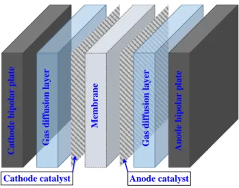
PEMFC is an electrochemical converter and continuously converts hydrogen energy into electricity power, heat and pure water [4]. The structural representation of a single PEMFC is depicted in figure 1.3 [8].
9
Figure 1.3. Structure representation of a single proton exchange membrane fuel cell.
Although the higher system efficiency and the zero-local-emission property versus thermal engines make PEMFC systems suitable for power generation in theory, many limitations in practical aspects, including the too high manufacturing costs, the too short durability as well as the shortage of hydrogen refueling infrastructures, greatly hinder its applications [9]. In other words, the high operation cost of vehicular PEMFC systems remains one major barrier towards the massive promotion of commercial FCHEVs. Although the efforts towards cost reduction of PEMFC systems can be made from structural design and material replacement perspectives (e.g. the development of more durable and cost-effective catalysts, etc.), breakthrough research progresses can hardly be made in a short time [10]. Hence, at current stage, a more practical solution is to use PEMFCs in an efficient and healthy manner for mitigating its operation costs [11].
Specifically, the operation costs of onboard PEMFC systems comprise two aspects: (1) the cost owing to hydrogen consumption and (2) the cost owing to fuel cell degradation. The hydrogen consumption costs can be effectively brought down by urging more fuel cell operation points towards the predefined high efficiency area [12]. Hence, the improved fuel cell working efficiency would lead to the reduction of hydrogen consumption and a better fuel economy.
In contrast, reducing the degradation costs of PEMFC requires a comprehensive understanding on the degradation mechanism of fuel cells, which is a complicated process involving multiple impact factors ranging from electrochemical to mechanical perspectives [10]-[14]. As reported in [13], the degradation of membrane electrode assembly (MEA) would greatly affect the normal operation of PEMFC, where the MEA degradation mainly originates from the following perspectives:
(a) Catalyst layer degradation mainly refers to the reduction of Electrochemical Active Surface Area (ECASA) [13]. One major reason for ECASA reduction is the platinum catalyst particles’ agglomeration, sintering and detach from the support material [15]. Moreover, fuel starvation caused by several operation conditions, including running under high loading, transient loading and during start-stop
M em b ra n e G a s d if fu si o n l a y er G a s d if fu si o n l a y er C a th o d e b ip o la r p la te A n o d e b ip o la r p la te
10
procedures, would intensify this process [16]. Another major cause of catalyst layer degradation appears when running at extremely low current densities, increasing the surface oxides on the platinum particles [17].
(b) Membrane layer degradation occurs mainly due to chemical attack, mechanical stress and/or thermal stress [16], [18], [19]. The former two are owing to the contaminants in the fuel [16] and the improper assembly or the congenital defects [18], respectively, where EMSs can do very little to prevent these defects. However, the thermal stress can be mitigated by properly regulating the PEMFC output power. This is because the high level of heat due to improper loading would reduce the membrane conductivity, increasing the fuel cell electrical resistance, thus compromising the fuel cell efficiency and generating more heats. Besides, excess heat can also cause the membrane drying, leading to the gas permeability [13].
(c) Gas diffusion layer (GDL) degradation shares the similar degradation mechanisms to the catalyst support materials [13]. For instance, fuel starvation at high or transient or on/off loading conditions intensify the oxidation of carbon. Besides, excess humidity at high current densities can cause flooding.
Figure 1.4. Relationship between PEMFC loading conditions and MEA performance degradation [14].
To sum up, the relationship between PEMFC loading conditions and MEA performance degradation is given in figure 1.4. Four PEMFC operating conditions, namely start-stop cycling [18], transient loading [10], heavy [20] and light loading [17], would intensify the MEA performance degradation, leading to the compromised fuel cell durability [14]. Therefore, to reduce the cost owing to fuel cell degradation, EMSs should prevent the occurrence of these operating conditions by controlling the power flow between fuel cell and battery. Specifically, for fuel cell lifetime prolongation, following suggestions should be systematically considered by the EMS designer:
(a) Avoiding frequent fuel cell on-off cycling.
MEA performance degradation Start-stop or transient load Heavy load Light load Fuel starvation Excess heat Excess humidity Oxidation of Carbon Conductivity Loss Gas permeability Flooding Surface Oxides Increment ECASA Reduction Catalyst Degradation Membrane Degradation GDL Degradation PEMFC loading
conditions Major causes for MEA performance degradation
Degradation categories
11
(b) Limiting the duration of fuel cell idling (working at extremely low load). (c) Restricting the changing rate of fuel cell output power/current.
(d) Preventing fuel cell working at extremely high loads. 1.2.1.2. Rechargeable battery pack
As the important energy storage device in the hybrid powertrain, rechargeable battery pack acts not only as the energy buffer to hold the DC bus voltage in charge-sustaining (CS) mode but also as the energy provider to deliver electricity power in charge-depleting (CD) mode. Lithium-ion battery is one of the most representative traction batteries for electric vehicles applications [7], whose working principle is schematically depicted in figure 1.5.
Figure 1.5. Schematic diagram of lithium-ion battery in discharge and charge mode.
Compared to PEMFCs, lithium-ion batteries have following two advantages:
(a) Fast dynamic response: Lithium-ion battery is a kind of energy storage systems, which directly converts the (stored) chemical energy into electricity power. Hence, in contrast to PEMFCs, it can more promptly response to the dynamic power requirement [1].
(b) High working efficiency: Due to the characteristic discrepancy in energy conversion processes between two power sources, the average efficiency of vehicular lithium-ion battery is about 90% [21], while the electrical efficiency for PEMFC is about 50% to 60% [1].
These advantages make Lithium-ion battery pack an ideal assistant power source within the hybrid powertrain especially during vehicle’s acceleration or regenerative braking phases. However, improper
-Li+ -Li+ -Li+ Anode (-) Copper current collector Electrolyte Separator Cathode (+) Aluminum current collector Li-metal Oxides Electron Li-metal Carbon Lithium ion -Li+ -Li+ -Li+ Anode (-) Copper current collector Electrolyte Separator Cathode (+) Aluminum current collector Li-metal Oxides Electron Li-metal Carbon Lithium ion
-Lithium-ion battery
Discharge
Charge
12
ways of battery usage could shorten its lifetime, compromise its working efficiency and thus threaten the vehicles’ drivability. Hence, a well-designed EMS should be able to reduce the battery’s operation costs and to prolong its onboard service time. According to previous studies [22], [23], following working conditions would affect the battery performance:
(a) Extremely low temperature: The performance of lithium-ion battery is very sensitive to the temperature. Low environmental temperature would slow down the battery’s chemical-reaction activity [24], leading to the reduced ionic conductivity of the electrolyte and the limited diffusivity of lithium-ion with the electrodes [25]. However, this deficiency is related to the characteristic and working principle of lithium-ion battery and thus can be hardly mitigated by the EMSs.
(b) Extremely high temperature: In contrast, high temperature would intensify the side reactions within the battery [22], leading to the loss of capacity [26] and the decrement of battery efficiency [27]. Furthermore, if the temperature is out of control, battery self-ignition and even explosion could happen in some cases [28]. Please note that, in most cases, high temperature effects are attributed to the high internal temperature of lithium-ion batteries during operation instead of the environmental temperature, which can thus be mitigated by properly governing the output behavior of battery [23].
(c) Over-charge [22]: On the one hand, this would increase the opportunity for electrolyte to decompose and have side reaction with the positive electrode. On the other hand, it is easy for lithium-ions to be reduced at the negative electrode.
(d) Over-discharge [22]: It is easy for the copper foil of the negative electrode to corrode and for the active material lattice of the positive electrode to collapse.
(e) High charge/discharge rate [29]: this would cause the rise of battery internal temperature, lead to the intensification of side reactions, and result in the fatigue and collapse of the active material crystal lattice.
Therefore, to extend the lifetime of lithium-ion batteries, it is necessary for EMS to limit the occurrence of the above-mentioned working conditions. Specifically, following control objectives should be integrated into the EMS framework:
(a) Maintain battery SoC within the predefined range to prevent battery over-charge or over-discharge. (b) Set upper limits for battery charge/discharge current to retard the rise of internal temperature.
1.2.2. Research progress of energy management strategies
In general, the term “energy management strategy (EMS)” refers to the system-level control strategies for splitting the external power demand towards multiple energy sources within the hybrid powertrain. Obviously, satisfying the driver’s power demand while respecting the physical constraints on each
13
component (e.g. the maximum output power limits of PEMFC etc.) is the basic goal of EMS. In parallel, the well-designed EMSs are expected to achieve multiple optimal objectives, where the predominant one is the fuel economy enhancement. Specially, for FCHEVs, prolonging the lifetime of PEMFC systems and ensuring the operation safety of battery pack are also regarded as the important objectives, since they are of great significance to bring down the vehicle’s maintenance costs (as analyzed in subsection 1.2.1). Despite distinct objectives realized by various strategies, the working principle of EMSs keeps almost identical. Served as the supervisory controller, EMSs interact with the lower-level controllers (e.g. DC/DC controller). The lower-level controllers respect the commands from the EMSs to control the output behaviors of DC/DC converter, DC/AC inverter and electric machine etc. [30]. Although numerous EMSs have been developed in previous studies, how to design an intelligent EMS to tradeoff among multiple contradictory objectives and how to release the computation burden for better real-time suitability, still remain challenging tasks. To better understand the developing history and the future trend of EMSs, a survey on the proposed EMSs from 1993 to 2018 is conducted. Please note that the EMSs in the literatures deal with both ICE-based and fuel-cell-based HEVs.
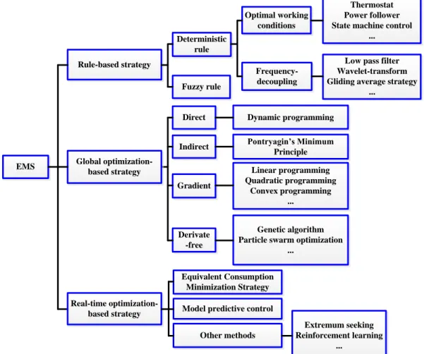
Actually, the crucial discriminating factor for any EMS is the control algorithms used for energy distribution. From the literature review, we found fourteen major control algorithms for EMS, including deterministic or fuzzy rules, deterministic dynamic programming (DP), quadratic programming (QP), game theory (GT), genetic algorithm (GA), convex programming (CP), particle swarm optimization (PSO), neural network (NN), Pontryagin’s Minimum Principle (PMP), equivalent consumption minimization strategy (ECMS), stochastic dynamic programming (SDP), model predictive control (MPC), reinforcement learning (RL) based strategy.
Figure 1.6 clearly depicts the EMS evolution details within the period from 1993 to 2018. Dating back to 1993, the basic EMS for HEVs was built based on the expertise knowledge and engineering experiences, for simply splitting power request between ICE and EM to bring down the tailpipe emission and fuel consumption [31]. However, those preset rules cannot guarantee the performance optimality until the assistance of DP to refine the rules [32] for EMSs or the employment of GA for multi-parametric tuning of fuzzy membership functions [33]. With the presence of DP, the global optimization results of EMS problem can be attained by minimizing the predefined cost function, given the knowledge of entire driving cycle [34]. Yet, the unavoidable computational burden, especially when a higher (discrete) grid resolution is required, makes DP-based strategy serve as the offline evaluation benchmark instead of being a real-time control strategy.
To overcome the deficiencies of DP, numerous researchers have switched their attentions to performing the optimal control in real-time, thus yielding three different real-time optimization-based EMSs, namely the instantaneous optimal control via PMP and ECMS [35], the approximate optimal control through NN [36] and SDP [37]. Afterwards, more advanced control strategies arose based on their
14
predecessors, including the improved-SDP [38], the adaptive-ECMS [39], the enhanced-NN [40] and MPC [41]. They were proven to be capable of further enhancing the vehicle's performance in face of real-world driving uncertainties. Meanwhile, compared to the single-objective optimization framework in previous studies, EMSs at this stage were evolving towards simultaneously achieving multiple objectives [42]. Most recently, with the rapid development of machine learning and artificial intelligence, Reinforcement learning (RL) was introduced as a novel model-free and adaptive control algorithm applied to EMS problems [43]. The performance of RL-based EMS may be far from global optimality at the trip beginning. However, it can eventually converge to the global optimality by stepwise updating the control policy through the action-reward interaction with driving environment [30].
Year Rule-based
EMS Improved Rule-based EMS with
DP or GA DP-based offline global optimal control Real-time local optimal control Improved real-time local optimal control Towards real-time global optimal control 1 9 9 3 1 9 9 8 2 0 0 1 2 0 0 3 2 0 0 4 2 0 0 6 2 0 0 9 2 0 1 1 2 0 1 2 2 0 1 3 2 0 1 4 2 0 1 8 2 0 1 9 Fuzzy or deterministic rules Rules or look-up tables optimized by DP or GA 2 0 1 5 E CM S
Local optimal control approaching global optimality
NN MP C Introduction of RL-based EMS Progress in RL to obtain global
optimal performance in real-time
Basic EMS Reduce CO2
emission
SD
P A-ECMS
Figure 1.6. Evolution of EMSs for HEVs from 1993 to 2018 [30].
Though the advent of RL algorithm exhibits great potential in obtaining global optimal performance in real-time sophisticated driving conditions, several un-well-solved issues could be threaten to its online implementation, including how to select a proper immediate cost for global optimization [30]; how to tradeoff between the heavy computational burden and the limited resources in the contemporary vehicular electronic control units (ECUs) [30]; how to build a cooperation framework between the
15
onboard ECU and the modern telematics systems, e.g. intelligent transportation systems (ITS), global positioning systems (GPS) and cloud computing systems [44]. Thus, the author believes that, at the current stage, RL is not the most appropriate candidate to realize the real-time optimal control for EMSs, although its implementation seems to be appealing.
In contrast, originating from model predictive heuristic control (MPHC), model algorithm control (MAC) and dynamic matrix control (DMC) from 1970s, the theory of model predictive control (MPC) has been established and intensively studied by numerous scientific communities [45]. Moreover, it has been successfully applied to many different industrial fields, including chemical industry, aerospace industry, automotive industry, etc. Considering its proven capacity of handling the multivariate constrained systems, the author decides to employ MPC for real-time decision-making for EMS development in this thesis. Moreover, the performance of MPC-based EMS is largely dependent on two essential factors, namely the accurate reference information as the guidance for vehicular power allocation (especially for PHEV applications), and the precise modelling of future driving disturbances for estimating the vehicle’s upcoming dynamics [45]. To provide with accurate predictive information for MPC decision-making, it is necessary to investigate the advanced driving prediction techniques, which would be discussed in detail in subsection 1.3.
1.3. Driving prediction techniques
Driving prediction techniques (DPT) refer to the algorithms that characterize the future distributions of various driving-related conditions, like vehicle speed, acceleration, driving pattern, etc. The predicted information is then integrated into the real-time optimization framework to form predictive energy management strategies (PEMS) and hence the quality of prediction would heavily affect the overall performance of PEMS [46].
1.3.1. Relationship between driving prediction techniques and predictive energy
management strategies
Traditional classification on EMSs is based on different control algorithms for power allocation (e.g. rule-based, optimization-based etc.). To clearly illustrate the relationship between the EMS and DPT, a novel classification criterion on control strategies for HEVs/PHEVs is put forwarded, considering whether or not the control strategies are assisted by the predictive information, whose block diagram is given in figure 1.7.
PEMS can be further classified into three sub-categories. “Full-knowledge” based PEMSs distribute energy flow according to the completely previewed traffic information, whereas “zero-knowledge” based PEMSs benefit no information from telematics systems. Please note that the major discrepancy between “zero-knowledge” based PEMSs and “N-PEMSs” (non-predictive EMS) is that the former takes advantage of the estimation of future driving conditions from DPTs, while the latter depends not
16
on any predicted information but only on the preset rules, human intuitions and expert experiences. Benefiting from the complete route-based information, “full-knowledge” based PEMSs could guarantee the global optimality to the utmost extent, but their performance can only be deemed as the offline benchmark rather than being used in real-time control. Therefore, as the major provider of predictive information in “partial-knowledge” and “zero-knowledge” based PEMSs, the DPTs would heavily affect the performance of these control strategies.
PEMS N-PEMS Full knowledge (100%) Partial Knowledge Zero Knowledge (0%) Terrain preview Speed limitation Traffic congestion level Road surface condition Weather conditions
Thermostat strategy Fuzzy logic control Frequency-based strategy
Deterministic rules
Neural network-based strategy
...
...
EMS
Figure 1.7. A novel classification of control strategy for HEVs/PHEVs.
1.3.2. Forecast objectives and algorithms
To enhance the PEMS performance, the precise characterization of future distribution of driving conditions is of great interests to researchers. Specifically, three major types of driving prediction objectives can be found within the existing literatures, namely driving cycle estimation, battery SoC reference prediction and driving pattern recognition.
1.3.2.1. Driving cycle estimation
Typically, a driving cycle is a series of data points representing the speed of a vehicle versus time [47], while a power profile is a series of data points denoting the vehicular traction power demand versus time. When the vehicle is running on a non-horizontal road (figure 1.8), its traction power demand 𝑃𝑡𝑟𝑎 can be calculated by Eq. (1.2) [1], where 𝑐𝑟 denotes the rolling resistance drag coefficient, 𝜌𝑎𝑖𝑟 the
17 𝑀 and 𝑣 respectively the vehicle weight and velocity.
v Fa Ftra Fg Mg Fr θ
Figure 1.8. Vehicle’s dynamics on a non-horizontal road.
𝑃𝑡𝑟𝑎 = 𝑣 ∙ 𝐹𝑡𝑟𝑎= 𝑣 ∙ (𝑀𝑔sin(𝜃)⏟ 𝐅𝐠 + 𝑐⏟ 𝑟𝑀𝑔cos(𝜃) 𝐅𝐫 + 0.5𝜌⏟ 𝑎𝑖𝑟𝑆𝑓𝑐𝑑𝑣2 𝐅𝐚 + 𝑀𝑣̇) (1.2)
As seen from Eq. (1.2), 𝑃𝑡𝑟𝑎 is closely related to the vehicular parameters (e.g. 𝑆𝑓, 𝑐𝑑, 𝑀 and 𝑐𝑟 etc.),
the driving cycles (𝑒. 𝑔. 𝑣 and 𝑣̇) and the road slope information (𝑒. 𝑔. 𝜃). The vehicular parameters are specified once the vehicle model is selected, while the road slope information can be previewed with the help of telematics systems or mobile applications. However, the driving cycle cannot be precisely estimated by the telematics systems since there are plenty of uncertainties on roads, like the stochastic distribution of traffic lights and the unexpected pedestrian movements [46]. To this end, it is important to carefully model the upcoming vehicle speed (or acceleration) trajectory. Generally, the algorithms for driving cycle estimation can be roughly categorized into three types:
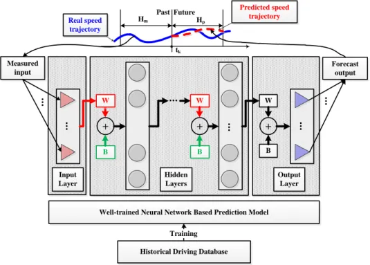
Artificial intelligence-based methods: Due to its proven capacity in time-series forecasting field [48], artificial-intelligence based approaches are deemed as the proper candidate for driving cycle estimation, where neural network (NN) is one of the most representative approaches [49]. The general working principle of NN-based prediction model is depicted in figure 1.9. As can be seen, the typical NN-based predictor comprises an input layer, hidden layers and an output layer. The input layer receives the historical speed samples, the hidden layers approximate the nonlinear relationship in a speed-series via proper weight and bias vectors, and the output layer transforms the output from the hidden layers into the desired forecast results.
Mathematically, the NN-based predictor can be written as a multi-input-multi-output function 𝑓𝑁𝑁,
which maps 𝐻𝑞 historical speed samples at time step k into the future ones in 𝐻𝑝 steps ahead [49].
[𝑣𝑘+1∗ , … , 𝑣𝑘+𝐻∗ 𝑝] = 𝑓𝑁𝑁(𝑣𝑘+𝐻𝑞−1, … , 𝑣𝑘) (1.3)
18
of neurons in each layer. As far as known, there is no uniform guideline for the setting of these parameters, meaning they have to be tuned manually to tradeoff between NN generalization capacity and the overfitting phenomena [50].
After the NN size is specified, the associated weights and bias should be adjusted to optimize the given performance index over the available dataset, which is termed as NN training. Please note that the training database usually comprises standard driving cycles, like the Federal Test Procedure-75 (FTP-75), Urban Dynamometer Driving Schedule (UDDS), or the GPS-collected speed profiles in real missions [49]. Since NN attempts to describe the complex, multivariate, nonlinear relationships in time series, and thus the time-consuming training processes are usually accomplished offline.
B + ... W B + Hidden Layers Input Layer Output Layer ... + ... B W ... W Past Future tk Hm Hp Real speed trajectory Predicted speed trajectory Measured input ... Forecast output ...
Well-trained Neural Network Based Prediction Model
Historical Driving Database Training
Figure 1.9. Schematic diagram of neural network-based velocity prediction model.
Markov Chain based methods: In realistic driving environment, vehicle’s operation can be influenced by many uncertain factors [46]. Therefore, the future distribution of vehicle velocity can be deemed as a stochastic process. As a powerful tool for stochastic modeling, Markov Chain is a commonly used approach to forecast the driving cycle or the vehicle’s power demand [49].
A Markov Chain (MC) is used to describe a stochastic sequence of possible events wherein the probability of each event depends only on the state obtained in the previous event [51]. The most important concept in Markov Chain is the transition probability matrix (TPM), as given in Eq. (1.4). TPM defines the future probability distribution of the Markov (stochastic) process, where its element in the 𝑖𝑡ℎ row and 𝑗𝑡ℎ column (𝑃𝑖,𝑗) is a conditional probability reflecting the occurrence of state transition
19
state is usually defined as the velocity, acceleration, or velocity-acceleration pairs, etc.[46].
TPM = [ 𝑃1,1 𝑃1,2 … 𝑃1,𝑗 … 𝑃1,𝑠 𝑃2,1 𝑃2,2 … 𝑃2,𝑗 … 𝑃2,𝑠 ⋮ ⋮ ⋱ ⋮ ⋱ ⋮ 𝑃𝑖,1 𝑃𝑖,2 … 𝑃𝑖,𝑗 … 𝑃𝑖,𝑠 ⋮ ⋮ ⋱ ⋮ ⋱ ⋮ 𝑃𝑠,1 𝑃𝑠,2 … 𝑃𝑠,𝑗 … 𝑃𝑠,𝑠] with ∑𝑠𝑗=1𝑃𝑖,𝑗= 1 (1.4)
The overall working flow of MC based prediction model is depicted in figure 1.10, including three working stages, where stage I (TPM group estimation) is conducted offline based on the available driving database, while stage II (driving data sample & encoding) and stage III (state transition estimation & decoding) are realized online for driving cycle prediction.
Definition of Markov states I Driving cycle database Interval Encoding Transition probability estimation TPM group Sampled driving data Interval Encoding Input Markov state Output
Markov state Decoding Prediction
II III
Figure 1.10. Working flow of Markov Chain based prediction model.
Exponentially decreasing model: Another simple but effective approach for driving cycle estimation is the exponentially decreasing model (EDM), which was originally proposed by H. Borhan in [52] and applied to MPC-based EMS for HEVs. This method forecasts the vehicle velocity by assuming the vehicle torque demand 𝜏𝑡𝑟𝑎 will decrease exponentially over the prediction horizon, as indicated by Eq.
(1.5). 𝜏𝑡𝑟𝑎[(𝑘 + 𝑖)𝑇] = 𝜏𝑡𝑟𝑎(𝑘𝑇) ∙ exp ( −𝑖∙𝑇 𝑇𝑑) (𝑎) 𝑣[(𝑘 + 𝑖)𝑇] = 𝑣(𝑘𝑇) +𝑀1∫ [ 𝜏𝑡𝑟𝑎(𝑡) ∙exp(−𝑡 𝑇𝑑) 𝑅𝑡𝑖𝑟𝑒 − 𝐹𝑔(𝑡) − 𝐹𝑟(𝑡) − 𝐹𝑎(𝑡)] 𝑑𝑡 (𝑘+𝑖)𝑇 𝑘𝑇 (𝑏) 𝑖 = 1,2, … , 𝐻𝑝. (𝑐) (1.5)
Where 𝜏𝑡𝑟𝑎(𝑘𝑇) is the known torque requirement at the beginning of the preview horizon, 𝑣(𝑘𝑇) the
sampled speed at the beginning of the prediction horizon, 𝑅𝑡𝑖𝑟𝑒 the vehicle tire radius and the detail
expressions of Fg, Fr and Fa are given in Eq. (1.2). Please note 𝑇𝑑 denotes the torque decay coefficient,
and it is the only parameter that needs to be tuned before online application. A larger 𝑇𝑑 contributes to
20 carefully adjusted under different driving patterns [53].
Telematics based methods: Thanks to the rapid development of modern telematics systems (e.g. GPS, ITS, Vehicle-to-Vehicle (V2V) communications), the forecast of future driving conditions can be made with higher credibility. Specifically, the preview of route-based information like upcoming traffic light distributions [54], speed limits [55], average traffic flow speed [56], future road grade [57], movement of preceding vehicles [58], drivers’ driving styles [59] and traffic congestion level [60] are utilized to reduce the prediction uncertainty, so as to improve the overall performance for HEV control strategies. For example, a higher prediction accuracy for future driving condition can be reached when considering the previewed topographic information [61]. Benefiting from such predictive information, the related EMSs for HEVs not only improve the fuel economy but also extend the lifetime of battery. Moreover, an ITS-enabled vehicle velocity-planning algorithm is proposed, aiming at scheduling the vehicles speed profiles based on the preview of traffic light distributions, so as to reduce the idle time of engine for better fuel economy [62].
1.3.2.2. Battery SoC reference estimation
Compared to HEVs, the plug-in property of PHEVs allows its onboard battery to be recharged by the external grid power, which, hence, enables a way towards better fuel economy by consuming the low-cost electricity energy. More importantly, for PHEVs, its global optimal fuel economy is closely related to the way of battery energy depletion. Therefore, an explicit SoC reference trajectory is indispensable as the guidance for battery energy allocation within the PEMS framework [63]. Please note that the global optimal SoC profile varies accordingly with different driving routes, and thus the estimation of SoC reference trajectory should take the previewed route information into account. From the related literatures, it can be found that the approaches for SoC reference estimation can roughly be categorized into three types:
Linear SoC reference model: The linear SoC reference model only requires the trip length Ltrip [64]
(or duration Ttrip [65]) information for SoC reference planning. Typically, the reference SoC is designed
to linearly decline from the initial (maximum) value to the terminal (minimum) one, implying the single SoC depleting rate over the entire trip.
Telematics-based SoC reference model: The second type of SoC reference planning method takes advantage of the real-time updated route information from modern telematics system (e.g. ITS, GPS, etc.). For example, in [56], the authors assumed that the average traffic flow speed on the selected routes can be previewed by the onboard GPS. Thereafter, dynamic programming (DP) is utilized to search for the optimal SoC trajectory on the previewed routes, where the obtained SoC trajectory is then used as the reference for MPC energy allocation control. The overall working flow of telematics-based SoC reference calculation approach is depicted in figure 1.11.
![Figure 1.4. Relationship between PEMFC loading conditions and MEA performance degradation [14]](https://thumb-eu.123doks.com/thumbv2/123doknet/14526504.723045/23.892.180.714.536.832/figure-relationship-pemfc-loading-conditions-mea-performance-degradation.webp)
![Figure 2.3. Control framework of the multi-mode SMS-based strategy [10].](https://thumb-eu.123doks.com/thumbv2/123doknet/14526504.723045/51.892.197.699.774.957/figure-control-framework-multi-mode-sms-based-strategy.webp)
![Figure 2.5. Schematic diagram of the wavelet transform: signal decomposition and reconstruction phases [15]](https://thumb-eu.123doks.com/thumbv2/123doknet/14526504.723045/53.892.182.710.515.790/figure-schematic-diagram-wavelet-transform-signal-decomposition-reconstruction.webp)
![Figure 2.8. Classification of global optimization-based strategies based on problem-solving approaches [1]](https://thumb-eu.123doks.com/thumbv2/123doknet/14526504.723045/56.892.118.770.260.603/figure-classification-global-optimization-strategies-problem-solving-approaches.webp)
![Figure 2.9. Optimization-based strategies for FCHEV: from offline to online [1].](https://thumb-eu.123doks.com/thumbv2/123doknet/14526504.723045/59.892.227.662.657.905/figure-optimization-based-strategies-fchev-offline-online.webp)

