HAL Id: tel-01126885
https://tel.archives-ouvertes.fr/tel-01126885
Submitted on 6 Mar 2015
HAL is a multi-disciplinary open access archive for the deposit and dissemination of sci-entific research documents, whether they are pub-lished or not. The documents may come from teaching and research institutions in France or abroad, or from public or private research centers.
L’archive ouverte pluridisciplinaire HAL, est destinée au dépôt et à la diffusion de documents scientifiques de niveau recherche, publiés ou non, émanant des établissements d’enseignement et de recherche français ou étrangers, des laboratoires publics ou privés.
bio-inspirés
Rémi Merindol
To cite this version:
Rémi Merindol. Assemblage couche-par-couche de nano-composites bio-inspirés. Chemical Physics [physics.chem-ph]. Université de Strasbourg, 2014. English. �NNT : 2014STRAE015�. �tel-01126885�
ÉCOLE DOCTORALE de Physique et de Chimie-Physique
Institut Charles Sadron (UPR22-CNRS)
THÈSE
présentée par :Rémi Mérindol
Soutenue le : 22 Septembre 2014pour obtenir le grade de :
Docteur de l’université de Strasbourg
Discipline/ Spécialité
: Chimie-Physique
Layer-by-layer assembly of strong bio-inspired
nanocomposites
THÈSE dirigée par :
M. FELIX Olivier Chargé de Recherche, université de Strasbourg M. DECHER Gero Professeur, université de Strasbourg
RAPPORTEURS :
M. WAGBERG Lars Professeur, KTH Royal institute of technology M. STUDART André Professeur, ETH Zürich
AUTRES MEMBRES DU JURY :
Mme DE COLA Luisa Professeur, université de Strasbourg
Acknowledgments
The work of this dissertation was carried out at the Institut Charles Sadron (ICS) in Strasbourg, France.
First, I would like to express my sincere gratitude to Professor Gero Decher and Doctor Olivier Félix, my PhD advisors, for their support, advices, kindness and optimism during my doctoral research. Thank you for the freedom you gave me on the project management, for letting me supervise several master students and for letting me enroll in teaching assistantship.
I would like to express my gratitude Professor Lars Wågberg, Professor André Studart, Professor Luisa De Cola and Professor Monika Shönhoff for having accepted to act as referees for my thesis work and for the interesting discussion during the defense and for their comments.
I would like to thanks Professor Christian Gauthier for letting me perform the mechanical characterization of the film in his lab and I am grateful to Damien Favier, Thierry Roland and Leandro Jacomine for their help and advices with the mechanical characterization of the films. I am grateful to Mathias Pauly for his advices on fibrilar nano-composites, in particular with the characterization of orientation. I would like to thanks Christophe Contal for teaching me AFM and letting me use the equipment in autonomy. I would also like to thanks Professor Valerie Keller for the XPS measurements, Cedric Leuvrey of the SEM images and Gerard Strub for his help restarting the dipping robot.
I would like to thanks the Ministère de l’Enseignement Supérieur et de la Recherche for the financial support. I would also like to thanks Ulrich Soling and SüdChemie (now Clariant) for the financial support and for providing the clays and Inventia for providing the microfibrillated cellulose.
A special thanks to Seydina Diabang and Charly Ou, the two master student I supervised, for their great work.
I would like to thank everyone that helped me with move forward with administrative task along this PhD Paule Vannson, Katia Bruzzone, Magalie Meyer, Annette Winter and Leyla Ermis.
Thanks the professors I worked with for making practical and tutorial session at the university a pleasure, Clarisse Hugenard, Matteo Mauro, Valerie Berle and Pierre Maubian.
Many thanks to all my colleagues and friends at ICS for their help and friendliness Marek, Teru, Andrew, Eric, Dasha, Olga, Maria, Akkiz, Patricja, Frank, Alexandra, Valentina, Joe, Paul, Xiaofeng, Christophe, Rebbeca, Natasha, David, Michel, Jonas, Florian, Hebing, Yulia, Souvik, Rahul, Sri, Heveline, Diana, Johana, Cesar, Tom, Adrian, Stephano, Nathalie, Anna, Tristan, Dido, Joseph, Lydie, Johan. Thanks also to my roommates that made me forget about work when I was back home. And to all my friends across France and Europe that reminded me that there is a life beyond the lab.
Huge thanks to Alliny for her happiness, advices and for being here during the up and down of this PhD.
A double thanks all the people I forgot; you definitely belong here.
Table of contents
Acknowledgments ... 3
Table of contents ... 5
List of abbreviations ... 9
Résumé en Français (Sumary in French) ... 10
Introduction ... 21
1 BIOLOGICAL AND BIO-INSPIRED STRUCTURAL MATERIALS... 24
1.1 Diversity and limits of biological materials as source of inspiration... 24
1.2 Mechanics of materials... 27
1.2.1 Stress-strain tests ... 27
1.2.2 Brittle, soft, or tough ... 29
1.2.3 Mapping material properties... 31
1.2.4 Composite materials ... 33
1.3 Biological materials ... 33
1.3.1 Efficient functional structures in nature ... 33
1.3.2 Structure and properties of nacre and bone... 36
1.3.3 Structure and properties of wood ... 38
1.4 Bio-inspired materials ... 40
1.4.1 Nacre-inspired artificial structures... 41
1.4.2 Wood-inspired artificial structures. ... 43
2 MULTILAYER THIN FILMS... 47
2.1 Nano-structured materials ... 47
2.1.1 Top-down versus bottom-up ... 47
2.1.2 Surface assisted production of thin films... 50
2.2 Layer-by-layer assembly ... 51
2.2.1 Principle of the LbL technique... 51
2.2.2 Control of the LbL build-up... 53
2.2.3 Diversity of building blocks and control of the super structure. ... 56
2.2.4 Diversity of supports... 57
2.2.5 Speeding-up the layer-by-layer assembly... 58
2.3 Nacre-like multilayers ... 60
2.3.1 Structure and solution behavior of clays ... 60
2.3.2 Building films containing clays ... 62
2.3.4 Mechanical properties of clay containing thin films...65
2.3.5 Other nacre-inspired multilayers ...68
2.4 Wood-like multilayers...70
2.4.1 Microfibrillated cellulose (MFC)...70
2.4.2 Layer-by-layer assembly of microfibrillated cellulose thin films. ...72
2.4.3 Properties of MFC‐containing thin films. ...73
2.4.4 Other wood-inspired multilayers. ...74
2.5 Mechanical characterization of thin films...75
2.5.1 Free-standing films ...76
2.5.2 Mechanical characterization of thin films ...77
3 MATERIAL AND METHODS...80
3.1 Materials and solution preparation ...80
3.1.1 Materials ...80
3.1.2 Preparation of clay suspensions ...81
3.1.3 Preparation of MFC suspensions...82
3.1.4 Preparation of polymer solutions ...82
3.2 Sample preparation ...83 3.2.1 Substrate cleaning ...83 3.2.2 Hydrophobic substrates ...83 3.2.3 Dip-assisted LbL assembly ...83 3.2.4 Spin-assisted LbL assembly ...84 3.2.5 Spray-assisted LbL assembly ...84 3.2.6 LbL assembly in QCM cell ...84 3.3 Imaging ...85 3.3.1 Optical photography...85
3.3.2 Atomic Force Microscopy (AFM)...86
3.3.3 Scanning Electron Microscopy (SEM) ...89
3.3.4 Orientation analysis ...90 3.4 Mechanical tests ...92 3.4.1 Sample preparation...92 3.4.2 Self-repairing experiments ...93 3.4.3 Tensile tests...94 3.4.4 Image correlation ...96
3.5 Monitoring the multilayer build-up...97
3.5.1 Ellipsometry ...97
3.6 Other characterization techniques ... 103
3.6.1 Dynamic Light Scattering (DLS)... 103
3.6.2 X-ray photoelectron spectroscopy (XPS) ... 104
4 CLAY-CONTAINING HYBRID MULTILAYERS ... 107
4.1 Clay suspensions and their assembly in films ... 107
4.1.1 Purification of clay suspensions ... 107
4.1.2 Influence of the purity of clay solution on the film growth and morphology... 110
4.1.3 Microscopic characterization of the different clays... 112
4.2 Controlling the build-up of LbL assembled clay films. ... 114
4.2.1 Nature of the polyelectrolyte and degree of ionisation. ... 115
4.2.2 Effect of drying during build-up by dipping ... 118
4.2.3 Spraying of clay-based films ... 121
4.2.4 Hydration phenomenon... 123
4.3 Hybrid films combining PDMS and Clays... 127
4.3.1 PDMS multilayers... 127
4.3.2 Combining clays and PDMS ... 130
4.4 Thick multilayers and their mechanical properties ... 133
4.4.1 Freestanding multilayers ... 133
4.4.2 Structure of the films ... 136
4.4.3 Influence of the amount of PDMS on the mechanical properties ... 139
5 FIBRILAR WOOD-INSPIRED NANO-COMPOSITES... 145
5.1 Dip-assisted assembly of MFC-containing multilayer... 145
5.1.1 Effect of the pH on the construction ... 146
5.1.2 Microstructure of MFC layers ... 148
5.1.3 Thick freestanding films ... 149
5.2 Mechanical properties of MFC multilayers assembled by dipping ... 153
5.2.1 Influence of the pH of assembly on the mechanical properties of the films ... 153
5.2.2 Plasticizing effect of water... 156
5.2.3 Self-repairing... 161
5.3 Spin-assisted orientation of the microfibrils... 164
5.3.1 Spin assisted build-up of MFC containing films ... 164
5.3.2 Macroscopic visualization of the orientation... 167
5.3.3 Microscopic semi-quantitative characterization of orientation... 168
5.3.4 Oriented films with record mechanical properties. ... 172
Bibliography ...179
Abstract ...190 Résumé ...191
List of abbreviations
AFM Atomic Force Microscopy CNT Carbon NanoTubes DLS Dynamic Light Scattering DNA DeoxyriboNucleic acid LB Langmuir-Blodgett LbL Layer-by-Layer
MFC MicroFibrillated Cellulose Milli-Q Ultrapure Millipore water OTS Octadecyltrichlorosilane
PAH Poly(Allylamine Hydrochloride)
PDDA Poly(DiallylDimethyl Amonium chloride) PDMS Poly(DiMethylSiloxane)
PEI Poly(EthyleneImine)
PMEMA Poly(Methyl vinyl Ether-alt-Maleic Anhydride) PVAl Poly(Vinyl Alcohol)
PVAm Polyvinylamine
QCM Qartz Crystal Microbalance RH Relative Humidity
RMS Root Mean Square THF TetraHydroFuran
Assemblage coucheparcouche de
composites bioinspirés
Résumé de Thèse en Français (Summary of the Thesis in French)
Les composites naturels sont à la fois polyvalents et très performants (résistant, auto-réparant, tenace, léger, …). Ces matériaux sont composés de renforts rigides (souvent fragiles) liés ensembles par une matrice molle et ductile. La structuration à l’échelle micro- et nanoscopique donne à ces composites une résistance et une ténacité plusieurs fois supérieures à celles de leurs éléments constitutifs. En comparaison les matériaux synthétiques ont des structures bien moins contrôlées, ce qui limite leurs performances. L’objectif de ces travaux est la fabrication de nano-composites polyvalents et performants s’inspirant des principes identifiés dans les matériaux biologiques. L’assemblage couche-par-couche permet un contrôle nanométrique de la composition et de l’architecture de films minces. En utilisant cette technique nous avons fabriqué d’une part des composites lamellaires combinant des nano-plaquettes d’argiles et des silicones imitant la structure de la nacre et d’autre part des composites fibrillaires à partir de cellulose dont la structure est inspirée du bois. Ces deux types de structures, renforcés par des nano-plaquettes ou des nano-fibres, sont à la fois transparents et extrêmement résistants, certains films ont même des propriétés d’auto-réparation. Cette thèse décrit la préparation et la caractérisation de ces composites aux propriétés multiples. Nous montreront aussi comment il est possible grâce à la technique couche-par-couche de contrôler l’architecture de ces films bio-inspirés et donc leurs propriétés mécaniques.
Des matériaux biologiques aux matériaux bioinspirés
Les matériaux structurels biologiques comme la nacre ou le bois sont à la fois légers, résistants, résilients et auto-réparants. Alors que ces matériaux sont composés d’éléments aux propriétés mécaniques limitées, soit mous (polymères amorphes, petites molécules), soit fragiles (minéraux, polymères cristallins), l’organisation à l’échelle nano- et microscopique de ces briques élémentaires aux propriétés mécaniques très contrastées conduit à des composites aux propriétés exceptionnels. Dans la nacre, par exemple, l’empilement compact de plaquettes inorganiques liées entre elles par un polymère mou conduit à une résilience près de cent fois supérieure à celle de ses constituants. Dans le bois l’organisation des fibrilles de cellulose est déterminée par la nature des sollicitations exercées sur la plante. Les fibres sont inclinées pour donner de la flexibilité aux jeunes arbres et alignées verticalement dans les troncs des vieux arbres pour soutenir le poids des branches et des feuilles.1 Des exemples d’organisation de matériaux naturels sont présentés dans la Figure 1. La Figure 1A montre un schéma de la structure de la paroi cellulaire du bois qui souligne l’importance de l’organisation des microfibres dans la structure du bois. A l’extérieur les fibres orientées aléatoirement permettent un contact résilient et efficace avec les autres parois cellulaires, tandis que l’alignement dans les couches internes rend la structure résistante, et enfin le vide central rend ces matériaux légers. Dans la Figure 1C on observe la tortuosité d’une fissure dans la nacre qui montre comment l’arrangement lamellaire des plaquettes minérales permet de dévier la propagation des fissures en augmentant de ce fait grandement la ténacité du matériau. La grande proportion de phase minérale dans la nacre (>90%) permet de conserver une forte résistance à la déformation, mais au contraire du carbonate de calcium constituant la phase minérale la nacre n’est pas fragile. Dans ces deux structures l’arrangement des nano-renforts, sous forme de fibrilles dans le bois ou de plaquettes dans la nacre, permet de nouvelles combinaisons de propriétés mécaniques : côté bois légèreté et flexibilité, côté nacre ténacité et résistance à la déformation.
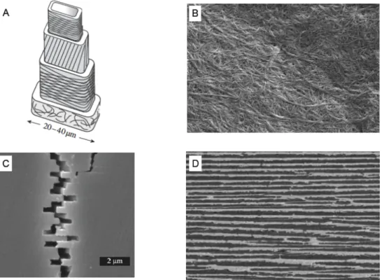
Figure 1. Matériaux structuraux biologiques et bio-inspirés. (A) Représentation schématique de la structure de la paroi cellulaire du bois. (B) Nano-papier préparé à partir de nano-fibrilles de cellulose.2. (C) Fissure dans de la nacre montrant les plaquettes de carbonate de calcium imbriquées les unes dans les autres. (D) Organisation lamellaire d’un composite à base d’époxyde et d’alumine structurée par congélation d’une solution de colloïdes. 3
Beaucoup de nano-renforts et de polymères disponibles pour la fabrication de composites artificiels ont des propriétés mécaniques supérieures à celles des composants naturels, cependant leurs assemblages en composites aussi performants que leurs homologues naturels restent un challenge. Par exemple l’incorporation de grandes quantités de nano-renforts dans une matrice polymère conduit à l’apparition de micro inhomogénéités par démixtion et à des matériaux fragiles. De même l’orientation précise de renforts lamellaires ou fibrillaires en masse, nécessaire à l’obtention de composites performants reste difficile. De manière générale le manque de contrôle à l’échelle micro- et nanoscopique diminue l’efficacité structurale des composites synthétiques.
L’objectif de la biomimétique est de s’inspirer des stratégies identifiées dans les matériaux naturels pour produire des composites synthétiques plus performants. De nombreux groupes travaillent sur la production de composites résistants et résilients imitant la structure de la nacre. La difficulté réside dans le contrôle de
l’architecture de ces matériaux. L’exemple dans la Figure 1D montre un composite lamellaire fabriqué par congélation d’une solution de particules d’alumine. Les cristaux de glaces grandissent sous forme de lamelles (suite à un gradient de température) et confinent les particules inorganiques sous forme de plaquettes par démixtion. Après lyophilisation de la glace, et frittage des particules d’alumine, il est possible de remplir les interstices de polymères pour conduire au composite. La ténacité de ce type de composites dont la structure est inspirée de celle de la nacre est dix fois supérieure à celle d’un matériaux de composition identique sans structuration.3 L’exemple dans la Figure 1B montre un film préparé par filtration d’une solution de nano-fibrilles de cellulose. La structure de ces films est similaire à celle du papier. Cependant, comme les fibrilles utilisés sont nanométriques (et non micrométriques comme dans le papier traditionnel), les interactions dans le matériau sont beaucoup plus nombreuses et mieux réparties. Bien que moins complexes que le bois ces films ont une résistance et une résilience exceptionnelle pour des polymères.2 Les exemples présentés ci-dessus ne sont qu’un aperçu des avancées technologiques s’inspirant de la nature et beaucoup reste à découvrir.
L’assemblage coucheparcouche
Le contrôle précis de l’architecture est l’étape clé pour la préparation de matériaux bio-inspirés performants. Développé par Gero Decher dans les années 90, l’assemblage couche-par-couche (abrégé LbL pour «Layer-by-Layer» en anglais) est facile d’utilisation, écologique et permet de contrôler à l’échelle nanométrique la composition et la structure de films supportés.4 Largement utilisé pour la
construction de films de polyélectrolytes, la technique LbL a été rapidement adaptée à de nombreux autres objets: colloïdes (quantum-dots 0D, nano-fibrilles 1D, nano-plaquettes 2D), protéines, cellules vivantes, ADN, polymères non chargés, petites molécules, …). Le principe simplifié de la technique LbL est présentée dans la Figure 2A en prenant pour exemple un couple de polyélectrolytes. Un substrat chargé positivement est mis en contact avec une solution de polyanion qui s’adsorbe à sa surface (interactions électrostatiques) conduisant à une inversion de la charge de surface. De fait cette étape est autolimitée car après inversion de la charge de surface les polyanions ne s’adsorbent plus. Le substrat est ensuite rincé pour enlever l’excès de
polyélectrolytes faiblement adsorbés, avant d’être mis en contact avec une solution de polycation. Ces derniers s’adsorbent à leur tour sur le support, et la charge de la surface redevient positive. Après rinçage on peut donc répéter le procédé pour déposer une nouvelle paire de couche et ainsi de suite jusqu’à obtenir l’architecture désirée. En première approche ce sont les multiples interactions électrostatiques entres les différents objets qui maintiennent la structure du film. Les détails des mécanismes dirigeant l’assemblage, la structure et la stabilité des films couche-par-couche sont cependant plus complexes, et toujours en cours d’investigation. Au delà de la diversité des objets pouvant être introduits dans les dépôts couche-par-couches, c’est la facilité d’utilisation qui fait la force de cette technique. La Figure 2B présente le matériel nécessaire pour préparer un dépôt couche-par-couche par trempage. D’autres méthodes comme la pulvérisation ou le spin-coating permettent d’accélérer le procédé de dépôt. Il est enfin possible d’incorporer plus de deux composés dans un même film et de contrôler l’architecture du film de manière arbitraire en choisissant la séquence de déposition.
Figure 2. (A) Principe de la technique couche-par-couche. (B) Montage expérimental pour un dépôt couche-par-couche effectué par trempage. (C, D, E) Représentation schématique des films que nous allons préparer : (C) nano-composite à base de fibrilles orientées aléatoirement dans le plan, (D) nano-composite à base de fibrilles orientées dans une seule direction, (E) nano-composite lamellaire à base de plaquettes orientées dans le plan.
Le contrôle de l’architecture des films composites assemblés par la technique LbL est un avantage clé pour la fabrication de matériaux bio-inspirés performants. Des
films s’inspirant de la nacre, combinant des argiles et du poly(vinylalcohol) ont déjà été assemblés par LbL.5 Ils sont transparents et leurs propriétés mécaniques sont exceptionnelles, avec un module d’Young atteignant 100 GPa et une résistance à la rupture de 400 Mpa. Ces films ont cependant une déformation à la cassure de l’ordre de 0.4 % et restent donc fragiles contrairement aux matériaux naturels qui sont bien plus tenaces. Pour obtenir des matériaux à la fois résistants et tenaces l’un des objectifs de cette thèse a été d’introduire des couches de poly(dimethylsiloxane) (un polymère extrêmement mou) dans ces films. La modulation de la quantité d’argile incorporée dans le film devrait permettre de contrôler de manière précise le module d’Young des films préparés et d’obtenir une fracture ductile (après la déformation plastique) nécessaire à l’obtention d’un file tenace. La technique LbL a aussi été utilisée pour fabriquer des matériaux inspiré du bois à partir de microfibrilles de cellulose.6 Cependant, les propriétés
mécaniques de ces composites sont bien en dessous des performances attendues pour des matériaux à base de microfibrilles de cellulose.2 En étudiant de nouveaux polymères et en contrôlant le dépôt, nous avons montré qu’il était possible d’obtenir de nouveaux composites très performants par LbL.
Pour les films à base de plaquettes d’argile (nanorenforts 2-D) l’utilisation de la technique de trempage permet d’obtenir des films lamellaires orientés dans le plan (Figure 2E). Pour les films à base de microfibrilles de cellulose (nanorenforts 1-D) cette même technique conduit à des films orientés aléatoirement dans le plan, or dans le bois c’est l’orientation des fibrilles qui apporte les performances mécaniques. Nous avons donc utilisé les forces de cisaillement induites lors de l’assemblage LbL par spin-coating pour fabriquer des films orientés encore plus résistants que les précédents.
Films inspirés de la nacre, combinant argiles et silicones
Les argiles sont un groupe de minéraux naturels composés d’un empilement de plaquettes mono-cristallines épaisses de quelques nanomètres et larges de plusieurs centaines de nanomètres. En présence d’eau les forces électrostatiques qui maintiennent la structure sont écrantées et les plaquettes se dispersent pour former une solution colloïdale. Les charges négatives présentes à la surface de ces plaquettes permettent cependant de les assembler en utilisant la techniqueLbL en les combinant avec un polycation. En premier lieu, nous avons étudié l’ assemblage d’argile avec des polycations forts (chlorure de poly(dimethyldiallylamonium)) et des polycations faibles (poly(vinylamine)) et nous avons montré que la vitesse de croissance était fonction de la densité de charge du polycation utilisé, de la nature et de la pureté des argiles. Nous avons ensuite étudié l’influence du séchage sur le régime de croissance des films multicouches à base d’argiles. Nous avons observé des phénomènes d’hystérésis lors du séchage et de l’hydratation des films qui induisent la transition d’une croissance linéaire vers une croissance exponentielle en l’absence de séchage.
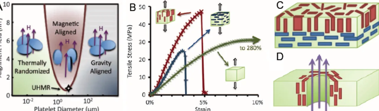
Ensuite, nous avons construits des films multicouches combinant des argiles et du poly(dimethylsiloxane) (PDMS). Pour cela nous avons fait réagir un poly(anhydride) avec un PDMS fonctionnalisé par des amines en bout de chaine. Les groupes réactifs disponibles du poly(anhydride) réagissent ensuite avec la poly(vinylamine), ce qui permet d’assurer la cohésion entre le PDMS et les argiles (Figure 3A, 3C).
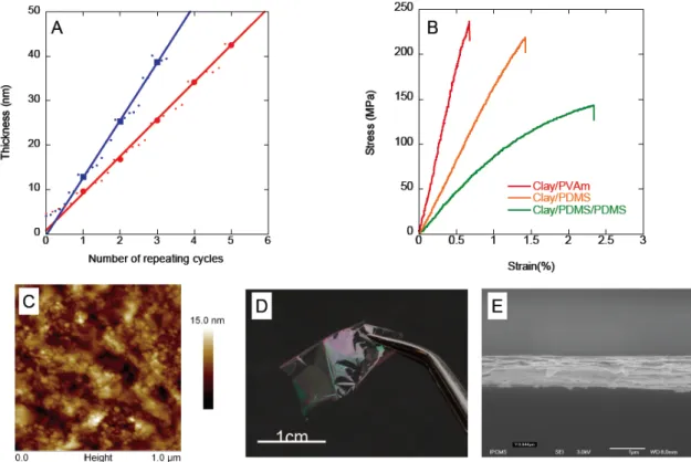
Figure 3 : (A) Croissance de films constitués d’argiles et de PDMS suivie par ellipsométrie. (B) Courbes de traction obtenues en fonction de la composition des films. (C) Image AFM de la surface d’un film multicouche après dépôt d’argiles. (D) Photo d’un film auto-supporté de 800nm d’épaisseur. (E) Image MEB d’une coupe transversale d’un film multicouche à base d’argiles.
La construction de films épais auto-supportés (~1 µm), nécessaire pour les mesures de propriétés mécaniques, a été effectuée en utilisant un robot de trempage automatisé remis en état de marche au cours de la thèse. Ces films sont transparents (Figure 3D) et présentent une architecture similaire à celle de la nacre (Figure 3E). Nous avons ensuite mesuré les propriétés mécaniques de ces films et montré qu’il était possible de faire varier le module d’Young entre 45 et 10 GPa en modifiant la composition des films (Figure 3B). Les contraintes à la cassure (130-230 MPa) et les modules obtenus pour les films composés uniquement d’argiles et de polymères sont comparables à ceux de certains alliages à base de magnésium, tout en étant légers et transparents. La ténacité des films varie aussi avec leur composition. Cependant même dans les films contenant le plus de PDMS la déformation plastique est limitée, ce qui empêche la fabrication de films tenaces. Il serait intéressant de continuer ces travaux en changeant la taille des particules d’argile incorporées dans ces multicouches ou les caractéristiques mécaniques de
la matrice polymère pour augmenter la déformation plastique de ces matériaux et améliorer leurs ténacités.
En effet, différentes particules de différentes formes et de différentes structures conduisent à des propriétés mécaniques différentes. A l’échelle nanométrique il reste beaucoup à découvrir sur les relations entres la formes des renforts et les propriétés mécaniques du composite. La suite de la thèse concerne l’étude de nano-composites renforcés par des nanoparticules unidimensionnelles, les microfibrilles de cellulose.
Films inspirés du bois, combinant microfibrilles de
cellulose et poly(vinylamine)
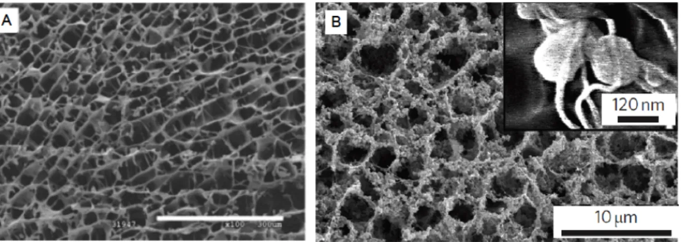
Les microfibrilles de celluloses sont les briques élémentaires qui donnent au bois sa structure et sa résistance mécanique. Elles ont un diamètre d’une vingtaine de nanomètres et une longueur qui peut atteindre quelques microns. Elles sont obtenues à partir des macrofibres présentes dans le bois par homogénéisation à haute pression et traitement chimique. La fonctionnalisation de la surface des microfibrilles par des groupements carboxylates permet d’obtenir des solutions colloïdales stables dans l’eau et d’incorporer ces microfibrilles dans des films multicouches via la technique LBL. Dans un premier temps, nous nous sommes intéressés à la construction de films contenant des microfibrilles de cellulose et de la poly(vinylamine) et nous avons étudié l’influence du pH de la solution de poly(vinylamine) sur la construction et la composition de ces films par trempage (Figure 4 A). Nous nous sommes ensuite intéressés à la structure de ces films et à leurs propriétés mécaniques en fonction du pH de construction (Figure 4 B). Finalement, nous avons étudié les variations de la résistance mécanique des films en fonction de l’humidité. Les propriétés mécaniques obtenues sont supérieures à celles du bois et comparables à celles des meilleurs composites à base de microfibrilles de cellulose. Ces films sont transparents, et certains (construits à pH élevé) s’auto-réparent en présence d’eau.
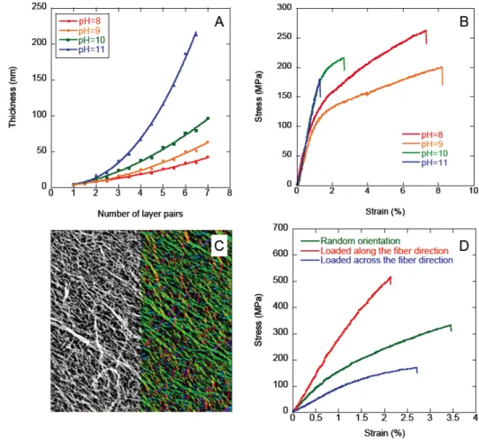
Figure 4 : (A) Croissance de films constitués de microfibrilles de cellulose et de poly(vinylamine) à différents pH suivie par ellipsométrie. (B) Courbes de traction obtenues en fonction du pH de construction. (C) Image AFM d’une couche de microfibrilles de cellulose orientée (à gauche); Traitement d’image permettant la visualisation et la quantification de l’orientation (à droite). (D) Propriété mécaniques des films en fonction de l’orientation et de la direction de sollicitation.
La dernière partie de la thèse concerne l’orientation des microfibrilles de cellulose dans les films multicouches en remplaçant le dépôt par trempage par un dépôt par spin-coating. Les films obtenus par cette technique présentent une orientation radiale des microfibrilles de cellulose. Nous avons caractérisé l’orientation des microfibrilles dans le matériau en combinant de l’imagerie AFM et un programme de caractérisation de l’orientation (Orientation J plug-in pour Image J) (Figure 4C). La résistance mécanique des films dans le sens des fibres est nettement supérieure à celle de films non orientés qui est elle même supérieure à celle des films dans le sens perpendiculaire aux fibres (Figure 4D). Avec une résistance mécanique de plus de 500MPa et un module de 30GPa ces films sont
comparables à des matériaux tels que des alliages d’aluminium ou certaines gammes de Kevlar®.
Les perspectives de ces travaux sont nombreuses; la combinaison de microfibres de cellulose et de particules d’argile pourrait par exemple conduire à de nouveaux matériaux encore plus résistant. Il pourrait aussi être intéressant d’assembler des films où l’orientation des fibres de cellulose varie dans l’épaisseur des films.
Lors de cette thèse, nous avons été amenés à remettre en marche un robot de trempage et à adapter les équipements de mesures mécaniques à l’étude de films micrométriques. Une fois ces outils opérationnels, nous avons pu préparer et caractériser des films inspirés de la nacre ou du bois en jouant sur divers paramètres (forme des renforts, nature des composants, architecture, méthode de dépôt, pH, ...). Ces nouveaux composites nano-renforcés présentent de multiples propriétés intéressantes, résistance mécanique, transparence, résilience ou encore auto-réparation. Au delà des premiers résultats obtenus ces travaux ouvrent les portes vers une meilleur compréhension des mécanismes gouvernant les propriétés mécaniques des nano-composites et donc vers la découverte de matériaux possédant de nouvelles combinaisons de propriétés mécaniques.
*
1. Lichtenegger, H.; Reiterer, A.; Stanzl-Tschegg, S. E.; Fratzl, P., Variation of cellulose microfibril angles in softwoods and hardwoods - A possible strategy of mechanical optimization. Journal of Structural Biology 1999, 128 (3), 257-269.
2. Henriksson, M.; Berglund, L. A.; Isaksson, P.; Lindstrom, T.; Nishino, T., Cellulose nanopaper structures of high toughness. Biomacromolecules 2008, 9 (6), 1579-1585.
3. Munch, E.; Launey, M. E.; Alsem, D. H.; Saiz, E.; Tomsia, A. P.; Ritchie, R. O., Tough, Bio-Inspired Hybrid Materials. Science 2008, 322 (5907), 1516-1520.
4. Decher, G., Fuzzy nanoassemblies: Toward layered polymeric multicomposites. Science 1997, 277 (5330), 1232-1237.
5. Podsiadlo, P.; Kaushik, A. K.; Arruda, E. M.; Waas, A. M.; Shim, B. S.; Xu, J.; Nandivada, H.; Pumplin, B. G.; Lahann, J.; Ramamoorthy, A.; Kotov, N. A., Ultrastrong and stiff layered polymer nanocomposites. Science 2007, 318 (5847), 80-83.
6. Karabulut, E.; Wagberg, L., Design and characterization of cellulose nanofibril-based freestanding films prepared by layer-by-layer deposition technique. Soft Matter 2011, 7 (7), 3467-3474.
Introduction
Biological structural materials possess fascinating combinations of properties such as lightweight, strength, shock resistance and self-healing. These materials are based on a limited number of compounds, which are either mechanically weak (amorphous polymers, small molecules) or fragile (minerals, crystalline polymers). In biological composites the combination of such materials with contrasting mechanical properties and the optimization of their micro- and nano-scale structures brings exceptional performance. For example the precise stacking of mineral platelets connected by soft polymers provides nacre or bones with a toughness orders of magnitudes above that of their individual components.1 In
wood the mechanical performances are brought about by the organization of the cellulose fibers, tilted fibers for flexibility in young trunks and vertical fibers for stiffness and compressive strength in older trunks as the weight of branches and leaves increases.2 Generally speaking the structure-property strategies evolved in biological materials are remarkably efficient.3
In comparison, the structural efficiency of synthetic composites is limited. Although the reinforcing particles in current structural composites have intrinsic mechanical properties above that of biological ones, their organization into mechanically efficient materials is still a challenge. Phase separation hinders the production of composites with homogeneous structure and large particle contents. The lack of micro- and nano-scale control over the architecture of man-made composites undermines their mechanical efficiency. The objective of bio-mimetism is to identify and use existing successful concepts responsible for the mechanical properties of biological materials in order to minimize learning cycle in the design of new materials, especially composites.
The conception of new bio-inspired composites requires a detailed understanding of biological and man-made materials. The first chapter of this thesis introduces the reader to the diversity of biological materials and provides notions on the properties and the mechanical characterization of common structural materials. Focusing on nacre, bone and wood we will then discuss the structure-property
relationships in biological composites. Finally we will review how these concepts have been applied in state-of-the-art bio-inspired composites.
The control of the nano- and micro-scale architecture is the bottleneck for the preparation of bio-inspired materials with good performance. Layer-by-layer (LbL) assembly is a cheap and environment friendly technique that offers a one dimensional nano-scale control over the structure and composition of thin films (also called multilayers).4 It has been used to prepare nacre-inspired multilayers from clay nano-sheets and poly(vinyl alcohol) with strength as high as 400 MPa.5 The contribution of layer-by-layer assembly to the preparation of platelets and fibrils containing multilayers is reviewed with focus on the mechanical properties of such composites.
The goal of this thesis was to take inspiration from nature and implement some concepts in mechanically resistant layer-by-layer assembled films. More precisely, our objective was to control through the conditions of LbL-assembly, the composition and the structure of the films prepared in order to investigate the structure-property relationships in such materials. Two concepts have been driving our work; the reinforcement of a soft polymer matrix by well organized anisotropic nano-particles and the prevention of crack propagation through the optimization of structural parameters. This work consists in the application of these concepts in nacre-inspired clay-based multilayers and wood-inspired fibril-based multilayers. In depth investigation of the parameters controlling the assembly of clay-based multilayer provided resources to optimize the construction of nacre-inspired films. The best nacre-inspired layer-by-layer assembled films reported reached high strength (400 MPa) but their strain at break was limited (0.4%) making these films brittle.5 Our strategy was to combine clay with poly(dimethylsiloxane), an extremely soft polymer. We have shown that it was possible to build multilayers with clay and poly(dimethylsiloxane) derivatives and to control their mechanical properties by simple variation of the constituents and film architecture.
For the preparation of wood-inspired structures we used microfibrillated cellulose, a promising class of nano-fibers extracted from wood. The composition of the LbL-assembled films was controlled by adjusting the pH of the solutions during deposition. We evaluated the influence of this parameter on the mechanical properties of the films. We also used water to plasticize the multilayers and
identified some experimental conditions where the film show self-repairing properties. Finally, we prepared and characterized oriented microfibrillated cellulose composites exhibiting record strength (490 MPa) as compared to natural wood8 and previously reported layer-by-layer assembled films.
1
Biological and bioinspired
structural materials
1.1
Diversity and limits of biological materials as
source of inspiration
Through evolution nature has selected a wide variety of function-specific multi-property materials. A single material can provide shape, nutriment transport, resistance and movements. These materials can in addition be self-healing and their colors serves as camouflage, mating signal or uv-protection. The diversity of structures and properties found in nature is colossal, yet some man made materials have unique features that are not found in biological materials.
Nature is especially good at making polymers, silk for example has a toughness surpassing that of steel.9 While a few DNA molecules store the information necessary to build a new living species from scratch. Industrial production of some regular polymer such as poly(cis-isoprene) is still challenging but it can easily be extracted from the latex secreted by Hevea Brasiliensis. Tires, gloves or balloons are still made of reticulated natural rubber that offers excellent elasticity, hydrophobicity and barrier properties. Nature also makes actuators, and motion mechanism. The flagellar motor of bacteria is a beautiful example of micro-propulsion.10 In eukaryote cells actin filaments and microtubules enable the diversity of motion that we know in the animal kingdom.11 Many photonic structures
species communication signals, and the micro lens array on the back of brittle star allows them to change colors.
Figure 5. Biological materials (A) Structure of DNA (deoxyribo-nucleic acid) (B) A butterfly (Genus Morpho) showing structural color. (C) Extraction of latex from Hevea Brasiliensis.
But nature lacks some properties needed for engineering applications. Magnetism for example, even if some organisms can sense and orient according to earth magnetic field13 their level of sophistication is low compared to man made
structures (hard drive or loud speakers). Another property missing to biological materials is electrical conductivity. Relying mostly on polymers and ceramic, nature can only produce materials with low conductivity. Even the nervous system based on the propagation of electrical signals relies on electrolyte solutions rather than conductive materials. At last, maybe the major drawback of natural materials is their shaping, as resistant and perfect as they can be, their shape and structure are defined by their function and can hardly be altered. The wings of butterflies are not meters wide, and nacre cannot be grown as car parts or bricks where its exceptional strength and toughness are needed.
Producing material that suits human needs in terms of shape, size and properties using the design principle found in natural materials is the aim of bio-mimicry. A very exiting field of material science that already found several everyday applications and where a lot is left to discover
For hundreds of years humans have taken ideas from their environments to create new objects, new techniques, and new theories. Romans were fighting in turtle like formation, Newton formulated his theory about gravity from the fall of an apple, and we travel in bird shaped planes. Our environment has always been a source of inspiration, conscious or unconscious. However there was a turn in the recent
Photo : Thomas Bresson
years with the systematic investigation of the design principle of natural structures in order to mimic them and produce bio-inspired objects.
The resemblance of the Gherkin tower (Former 30 St Mary axe) in London with a deep sea-sponge (Figure 6 A and B) may be accidental14 but it is nevertheless remarkable. Both share a tubular structure reinforced along four axes (horizontal, vertical and two spiraling diagonals) bringing high mechanical resistance with limited amount of structural material. The sponge needs water flowing through its structure to filtrate nutriments while the “Gherkin” uses its open structure to allow ventilation and save energy.
Figure 6. Comparison of biological and man-made structures. (A) Photograph of a deep sea-sponge (see also Figure 11 A).15 (B) Photograph of the ”Gherkin” a building located in London.14 (C) SEM image showing the longitudinal micro-structure of cedar wood (see also Figure 15 D). (D) Schematic representation of the core structure of Nordic skis (taken from www.fischersports.com).
There are also plenty of examples of bio-inspired structures in sports and high technology. Nordic skis for example have a structure that combines principles found in wood and porcupine quills (Figure 12 and Figure 6 C and D). The hard outer skin with a cellular filling, found in porcupine quills, brings lightweight and bending resistance. On the wood side the vertical alignment of the cells in the ski provides enough compressive strength to hold the weight of the skier.
Velcro scratch, present on shoes and clothes, owes a lot to the tiny hooks found on the surface of cocklebur’s fruits. These fruits stick to the fur of animals upon contact, travel with the animal and are seeded far from the mother plant when the animal scratches itself. In the same way that Velcro fasten upon pressure and detach upon pulling.16 Following these successes on the macroscopic scale, the
current research is focusing on mimicking biological structures at the micro and nano-level.
Among biological structures, the ones providing structure and protection to plants and animals are especially interesting. Wood, nacre and bone are strong, tough and light a combination of properties sought after in engineering composites. While the elementary bricks that compose them are either weak or brittle, their organization takes the best of each to produce a material that is both strong and tough. The translation of nature’s design principles in man-made nano-composites is promising, yet the description of structure-properties relationships in biologic and bio-inspired materials requires notions of mechanics of material.
1.2
Mechanics of materials
This section introduces the basic concepts for the mechanical characterization and description of structural materials such as polymers, ceramics, and metals.
1.2.1 Stressstrain tests
Stress strain tests, or tensile tests, consist of recording the force needed to deform a sample at a constant strain rate up to rupture (Figure 7).
Figure 7. Schematic representation of stress-strain tests. The sample is pulled at a constant speed and the applied force (F) is recorded as function of the strain (ε).
These tests are the most popular mechanical characterization technique for studying structural materials.17 They are easy to set up and intuitive, if one wants to know how resistant is a material one simply pulls on it. Tensile tests only probe the macroscopic behavior of the material under tension, however the macroscopic
properties of the material depends on its nano- and microscale structure. Other tests can complete the description of the mechanical behavior of the material:
- Dynamic mechanical analysis gives information about the dependence of the mechanical properties to the solicitation speed.
- Compression, shear, or flexion tests correspond to different types of solicitation of the material.
- Nano-indentation and AFM directly probe the properties of the material at the micro or nano-scale.
Many other mechanical tests exist, but often they probe properties for specific applications. In this manuscript, we will focus on stress-strain tests to allow easy comparison between different materials.
In tensile tests the force needed to deform a sample depends on its size, and more precisely on its cross section (A), while the distance of deformation (L-L0) depends
on the initial length (L0) of the sample. Considering the stress (σ) instead of the
load (F) and the strain (ε) instead of the distance of deformation allow to get rid of these geometrical constrains.
€ σ = F A Equation 1 € ε=(L − L0) L0 Equation 2
This way stress and strain measured are representative of the material properties and independent of the sample size, which makes comparison between different samples possible.
The quantitative treatment of tensile test data yields a curve were the stress recorded is plotted as function of the strain applied on the sample. Typically three properties can be obtained from this curve:
- The Young’s modulus (E) is slope at the origin of the stress-strain curve, it corresponds to the property of the the material to resist to deformation. - The stress at breaks (σmax) that corresponds to the strength of the material.
- The strain at breaks (εmax) that corresponds to the maximum strain the
In a more detailed interpretation the tensile test curve (Figure 8) is divided into three parts.17 The first part corresponds to the elastic regime at low strain (in red) where the stress is proportional to the deformation of the material. The elastic deformation is reversible, meaning that the material relaxes back to its original shape if the load applied to the material is removed. The last part is the plastic regime at high strain where the material deforms with only a small increase of the strain. Plastic deformation corresponds to a failure of the material structure it is therefore irreversible. Between these two regimes, the yield point corresponds to the transition from elastic to plastic behavior.
Figure 8. Schematic representation of a stress strain curve.
The area under the curve (red, white and green) corresponds to the total energy needed to break the material. The energy stored in the elastic deformation of the material will be released after breaking, while the energy associated with the plastic deformation is dissipated or absorbed by the material.
There is a multitude of materials with various mechanical properties. This single curve is only a simple example used to illustrate the general terms. The next section will present material properties that can be extracted from the shape of a given stress-strain curve.
1.2.2 Brittle, soft, or tough
The choice of a structural material with given mechanical properties provides its mechanical resistance and shape to an object. Their core characteristics are,
therefore, their strength (the maximal load they can handle before breaking), their toughness (the maximal energy they can handle before breaking) and their ability to resist deformation (Young’s Modulus). There is no good or bad material, the property of an object must always be in equation with an application. A rubber knife and a stone pillow are equally useless. Three of the most important types of material behavior are presented Figure 9.
Figure 9. Three types of stress-strain curves.
Strong and brittle materials (red curve) deform elastically and have a high Young’s modulus (e.g. glass). This type of material resists well to deformation, but as the area under the curve is limited, such materials is very sensitive to shocks and break easily. They are also sensitive to flaws because they don’t dissipate energy (purely elastic). If a pre-cracked material is deformed, the energy accumulates near the crack and when the material fails the energy released leads to a fast development of the crack and premature breaking of the material. These materials exhibit better performance in compression than in tension and need protection against shocks for better performance.
At the other end of the range, weak and ductile materials (green curve) have a small elastic and a large plastic regime (e.g. dough). These materials are easy to deform and nearly insensible to flaws and shocks. As their structure is irreversibly modified upon solicitation, they find few applications as structural components. Strong and tough materials (blue curve) combine a high Young’s modulus with a plastic deformation (e.g. steel). These materials resist well to deformation and
shocks while being nearly insensitive to flaws and defects. They are good candidates for demanding structural applications.
To finish, elastomeric materials (not represented in Figure 9) combine a large elastic regime with a low Young’s Modulus (e.g. rubber). They are easy to deform and do not break upon shocks but they can be sensitive to flaws. They are used for objects subject to large reversible deformation.
The material selection for the design of an object is a delicate task. In order to visualize the properties of material and facilitate the material selection engineer usually use properties maps of materials, also called Ashby plots.18
1.2.3 Mapping material properties
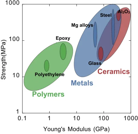
There are three main classes of homogeneous structural material: polymers, metals and ceramics. Some mechanical properties of the three class of material have been presented Figure 10.18-20 The strength values reported for polymers and metals correspond to yield strengths, which are the stress at the end of the elastic deformation; they are typically lower than the maximal stress for materials with a plastic deformation. For ceramics the modulus of rupture reported corresponds to the maximal bending stress that a beam of material can handle. For ceramics it is typically higher than the tensile strength and lower than the compressive strength. Polymers usually have Young’s moduli below 10 GPa and a maximal strength below 200 MPa (with some exceptions like polyaramides whose Young’s modulus and strength reach 130 GPa and 3000 MPa respectively). Their mechanical behavior range from liquid to brittle solids, and a single polymer often switches from brittle at low temperature to elastomeric or tough at higher temperatures (and ductile or liquid at even higher temperatures). They are light compared to the other classes of structural material (density between 0.5 and 2.5) and generally easy to shape as they melt below 300 °C (extrusion, injection molding, coating or thermoforming) but they are sensitive to environmental conditions (UV, solvents, heat) and loose their mechanical properties with time.19
Metals have Young’s moduli between 30 and 300 GPa, and maximal strengths between 200 and 3000 MPa. They are generally tough but their high density (between 2 and 20) makes them undesirable for lightweight applications. Naturally occurring as oxides, they need to be reduced at high temperature before being
shaped using high mechanical strength (rolling, embossing) or high temperatures (extrusion, casting), which makes them generally expensive. It is the class of materials with the highest electric and thermal conductivities but they tend to corrode for example in the presence of water.19
Figure 10. Ashby plot showing the strength and Young’s modulus of polymers (yield strength), metals (yield strength) and ceramics (modulus of rupture) at ambient conditions.18
Ceramics combine high Young’s modulus between 100 and 600 GPa (up to 1000 GPa for diamond), with high compressive strength from 1000 to 10000 MPa. But their brittle behavior limits their strength in traction (and the modulus of rupture plotted above) to a tenth of the compressive value. With a melting point above 1500-2000 °C, they are extremely difficult to shape, but they keep their mechanical properties even at very high temperature. Ceramics are generally insensitive to environmental conditions (UV, solvents, temperature) and can be used as electric or thermal insulators.
Polymers
Metals
Ceramics
Mg alloys Steel Epoxy Polyethylene Al2O3 Glass1
10
100
1000
0.1
1
10
100
1000
S
tr
e
n
g
th
(M
P
a
)
1.2.4 Composite materials
Some combinations of properties are difficult to obtain from a single material, for example lightweight and toughness or conductivity and transparency. Nature and humans solved this problem with composites. In composites two or more materials are combined to reach a specific set of properties that could not be obtained otherwise (at least not at similar costs). Some examples can be found in everyday life, reinforced concrete combines the compression resistance from concrete and the tensile strength from steel. While in aeronautics carbon fiber composites are light, strong and tough.19
The history of man-made composites started with Egyptians where straw was mixed with clay to improve the resistance of bricks. Since then composites science improved and diversified, but natural materials are still far ahead. From wood to bones and shells, the degree of precision and level of sophistication achieved by nature is mesmerizing.
1.3
Biological materials
Nature produces materials in restricted conditions (aqueous medium and room temperature), using only a limited set of elements (hydrogen, oxygen, cabon, nitrogen, sulfur, phosphorus, and calcium). Nevertheless, these materials have shock resistance, flexibility, or strength beyond expectations. In this section we will discuss the mechanisms that give natural nano- and micro-composites their exceptional mechanical properties.
1.3.1 Efficient functional structures in nature
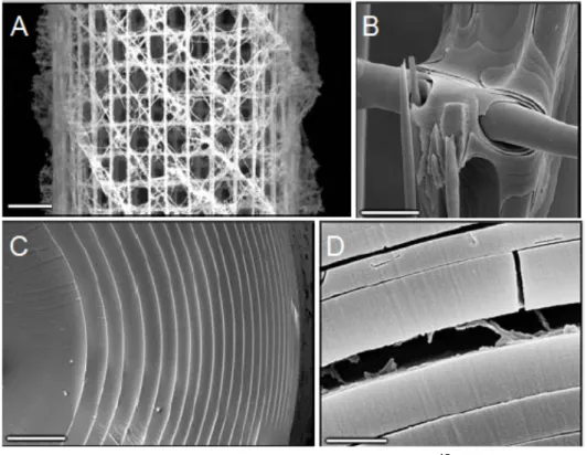
Famous for the beauty and efficiency of its structure, Euplectella sp, is a deep-sea sponge. This multicellular animal lives attached to the seabed and filtrates water to feed. It relies on a flexible and resistant skeleton to maintain its open structure in the currents. Several mechanisms bring strength and toughness to its highly open structure.
Figure 11. Structure of deep sea sponge Euplectella sp.15 (A) Macroscopic image of the cage structure. Scale bar 5 mm. (B) SEM image showing that crossing spicules are cemented with laminated silica layers. Scale bar 25 µm (C) SEM image of a cross section of a spicule. Scale bar 5 µm. (D) SEM image of a fractured spicule showing organic interlayer. Scale bar 1 µm.
At the macroscopic level (Figure 11A) the skeleton consists in a regular network of spicules (silica fibers) oriented vertically, horizontally and in the diagonal of the tubular structure. Each intersection is reinforced by cementation to ensure cohesion (Figure 11B). This arrangement provides resistance in flexion, tension and compression with a minimum amount of material. But the exceptional resistance to shocks comes form the microstructure of the spicules. Composed of concentric microscale layers of silica glued together with nanoscale organic interlayers, they have an excellent damage tolerance and prevent crack propagation. This structure has a fracture toughness twice that of monolithic silica while its modulus is only decreased by 20%.21 It is amazing how such a small amount of soft mater can improve toughness of the structure by crack deflection and energy dissipation.
Porcupine quills are another beautiful example of precise architecture-function relationships. In combination with their lightweight, these defensive weapons are designed to resist high compressive loads without bending or buckling.
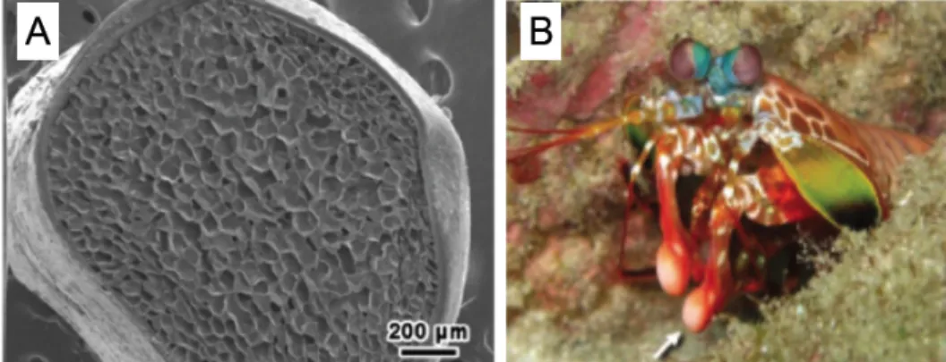
Figure 12. (A) SEM image of the transversal cut of a porcupine quill (Erethizon).22 (B) Photograph of a stomatopod. The arrow is pointing its club.23
To make a plain cylinder lighter, one can remove the inner part and turn-it into a tube, but the resistance to bending and buckling is then dramatically decreased. Porcupine quills are filled with a closed-cell foam that maintains lightweight while enhancing the compressive strength (Figure 12A). Yang et al.24 showed that when
the foam is removed from the quills the critical buckling strength is divided by three and the Young’s Modulus by two. This is a perfect example of how to minimize mechanical loss upon weight reduction.
The natural material with the highest impact resistance can probably be found in the dactyl clubs of the stomatopod “Odontodactylus scyllarus”, a tropical shrimp (Figure 12B). It uses these weapons to smash its preys, sea shells or other shrimps, themselves protected by some damage tolerant armors. The architecture of these club described by Weaver et al.23 combines an outer layer of high
modulus, supported by a material whose hardness varies periodically. Their inner structure deflects and stops cracks while the hard outer layer minimize erosion. These clubs are so efficient that when kept in captivity, these shrimps break the glass of the aquarium.
From spider silk, a semi-crystalline elastomer with hard β-sheet linked with softer amorphous segments, to the strong and porous armor of lobsters that consist of an helical arrangement of chitin fibers, the diversity of biological composite is fascinating.1, 25-28 A common concept in natural composites consist in the precise organization of hard blocks, providing the material with strength, with a soft matrix that prevents cracks propagation and improves the toughness. This concept finds
its best examples in nacre, bones, and wood, which respectively bring shape to mollusks, vertebrae and plants.
1.3.2 Structure and properties of nacre and bone
Nacre and bones are made of small anisotropic particles embedded in a flexible matrix. These two materials have a hierarchic structure that is optimized for toughness.29-31
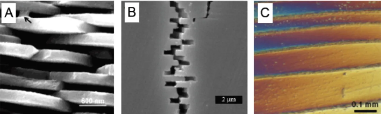
Figure 13. Hierarchical structure of red abalone shell: (A) SEM image showing the organization of calcium carbonate platelets of nacre. An arrow indicates the organic glue bridging them.32 (B) SEM image of a fractured nacre. (C) Optical micrograph of intermediate meso-layers found in nacre.33
Red abalone shell, one of the most studied types of nacre has precise architecture that combines multiple toughening mechanisms. At the micro-scale (Figure 13A), nacre consists of a dense stack of calcium carbonate platelets hold together with organic glue and mineral bridges. The high content of hard inorganic platelets (over 90%) provides nacre with its high Young’s modulus and strength. The size of the platelets and the resistance of the glue are such that when nacre starts to fracture, the inter-digitated platelets slide against each other instead of breaking (Figure 13B). In consequence, the material undergoes plastic deformation before fracture, which increases its toughness. At larger scale the meso-layers (Figure 13C) and the multiple platelet-glue interfaces deflect and hinder crack propagation enhancing further the energy needed to break this material. Other toughening mechanisms have been proposed such as interlocking of the platelets,29 fracture of mineral bridges between platelets and friction associated to platelets roughness.33 All these
mechanisms are probably contributing to the extreme fracture resistance of this material. Nacre is thousand times tougher than its components.25
Figure 14. Hierarchical structure of bones.1
With a different organization, bone is built according to a similar principle, hard inorganic platelets embedded in a soft polymer matrix. In bone hard hydroxyapatite particles are stacked together with soft collagen (and some other biopolymers). These stacks are assembled in fibrils themselves grouped in bundles. While in nacre the lamellar structure is optimized to resist cracks and out of plane bending, the structure of bones is designed to resist more diverse solicitations such as compression and bending in multiple directions. The bone structure is overall isotropic but specifically reinforced at weak points. Osteons, for example, the holes through which blood brings nutriments to the marrow, create weak points in the structure of bones. These holes are surrounded by lamellae of fiber bundles that prevent crack formation and propagation.34 This specific reinforcement of weaknesses maximizes the overall strength and shock resistance of bones. Since
each bone is designed to resist specific solicitations their structure is highly variable.
Several mechanisms have been reported to explain the strength and toughness of bone. The size of the inorganic platelets is small enough to be insensitive to flaws and to reach their maximal theoretical strength.35 The different levels of organization lamellae, bundles and fibers improve crack deflexion by multiplying the interfaces36 while crack bridging37 and ductile deformation of collagen dissipate energy. Bones are also self-healing, stress induced micro cracks are continuously repaired preventing weakening of the structure with time.
The precise combination of hard anisotropic platelets and soft polymer brings to bones and nacre their strength and toughness. In wood a similar reinforcement is brought by strong cellulose fibers embedded in a softer polymeric matrix. If the basic principle is the same some specific reinforcement strategies have been developed in this fiber reinforced polymer-polymer nano-composite.
1.3.3 Structure and properties of wood
A large variety of mechanical properties exists in plants, soft tissues in fruits to flexible branches or rigid trunk. Surprisingly only four main components are found in the cell wall of these structures: cellulose, hemicellulose, lignin and pectin. Among these molecules, cellulose has the most interesting mechanical properties (Young’s modulus above 100 Gpa and strength probably reaching 1 GPa), while hemicellulose, lignine and pectine behave like regular polymers (Young’s modulus around 3 GPa and strength around 50 MPa). The variety of properties found in plants emerges from the organization and structure of their cell walls.8
Wood, a material used for thousands of years to build houses, boats and weapons, combines toughness, strength, and lightweight. These properties are still sought after in engineered composites. In the present section, we discuss how its structure controls its mechanical properties.
Figure 15. Hierarchical structure of wood. (A) Structure of cellulose. (B) Organisation of cellulose microfibrils in macrofibrils. (C) Structure of the wood cell wall with black lines representing the cellulose macrofibrils. (D) SEM image showing the cross section microstructure of cedar wood.8
Wood is mostly composed of cellulose (Figure 15A) that forms long micro-fibrils with alternating crystalline and amorphous parts. The fibrils have a thickness of 3-4 nm and a length that can reach several micrometers. The crystalline parts are composed of 25 chains of cellulose arranged in twisted structure with a diamond cross section.38 These micro-fibrils form bundles (macro-fibrils) with a diameter around 20 nm (Figure 15B). The cell wall of wood consists of four concentric layers of macro-fibrils bound together by hemi-cellulose (Figure 15C). In each layer cellulose micro-fibrils have a defined organization, the external layer (primary layer) with randomly oriented fibers act as interface with neighboring cells, while the secondary layers (the three internal layers) represents up to 80% of the volume of the cell wall and is responsible for most of the structural properties.
Lichtenegger et al.39 used micro X-ray diffraction to study the secondary layer. They were the first to prove that cellulose fibrils are oriented in a spiral around the wood cell. Variation of stiffness in the different parts of a tree have been linked to the angle that these fibrils do with the main axis of the wood cell.2 Large angle leads to more flexible structure while lower angle bring stiffness and compressive strength. The fibers are tilted in young wood to bring flexibility and resistance to shocks and wind. On the contrary, the tilt decreases in older wood because strength and stiffness are required to hold the weight of the increasing number of leaves and branches.
Wood is an anisotropic structure. Wood cells are elongated structures aligned along the main direction of the trunk or branch (Figure 15D and Figure 6C). Cellulose fibers are globally aligned with the direction of the cells (they actually