HAL Id: hal-01565977
https://hal.laas.fr/hal-01565977
Submitted on 26 Jul 2017
HAL is a multi-disciplinary open access
archive for the deposit and dissemination of
sci-entific research documents, whether they are
pub-lished or not. The documents may come from
teaching and research institutions in France or
abroad, or from public or private research centers.
L’archive ouverte pluridisciplinaire HAL, est
destinée au dépôt et à la diffusion de documents
scientifiques de niveau recherche, publiés ou non,
émanant des établissements d’enseignement et de
recherche français ou étrangers, des laboratoires
publics ou privés.
Autonomous Aerial Vehicle Based on Non-Monotonic
Logic
Vilchis Medina, Pierre Siegel, Andrei Doncescu
To cite this version:
Vilchis Medina, Pierre Siegel, Andrei Doncescu. Autonomous Aerial Vehicle Based on Non-Monotonic
Logic. 3rd International Conference on Vehicle Technology and Intelligent Transport Systems
(VE-HITS), Apr 2017, Porto, Portugal. 6p., �10.5220/0006304002360241�. �hal-01565977�
Jos´e Luis Vilchis Medina
1, Pierre Siegel
1and Andrei Doncescu
2 1Aix Marseille Universit´e, CNRS, LIF, Marseille, France2LAAS, CNRS, Toulouse, France
Keywords: Autonomous Motor-glider, Non-monotonic Reasoning, Default Logic, Decision-making, Solar Cells, Artifi-cial Intelligence.
Abstract: In this article we study the case of an autonomous motor-glider. The aims of the aircraft is to maintain its flight as long as possible, taking advantage of the rising air from the ground, known as thermals, despite of limited energy resources and possible external influences, such as turbulences. The pilot task being to make decisions with incomplete, uncertain or even contradictory information, as well as driving to the desired path or destination. We propose the formulation of a model from the point of view of logical theory, using non-monotonic logic and more specifically default logic, to tackle these problems. Finally, we present the results of a simulation for further application in a glider(reduced model) which use solar cells for power management in embedded system.
1 INTRODUCTION
The glider is one of the most relevant aircraft, in terms of the ratio of the distance traveled and the loss of altitude. Making it more efficient to fly than other aircrafts. In this paper, we focus on an autonomous glider(reduced model), a convenient choice(cost) in terms of weight and aerodynamics. The principle of a glider is that it uses the “vertical” wind (thermal and dynamic energy). It is to “climb”, which that means to increase in altitude and reach an updraft, while “de-scent”, expresses the rate of descent in a downward burst. “Zero” descent means that updrafts are strong enough to maintain flight, but not enough to allow climbing. As in the nature, there are various species of birds using the same principle. For example: alba-tross and condor. To perform those flight maneuvers, a pilot must take decisions concerning the flight sit-uation from the cockpit. He has access to different instruments showing altitude, wind speed, inclination of the aircraft, etc. Another constraint is that he also needs to find thermals, respecting the aeronautical and security regulations. Taking these considerations into account, the pilot must follow his desired flight path applying control commands. Increasing or decreasing altitude, turning to the right or left, etc. These rules are applicable to many types of aircraft. We intro-duce a discrete model of flight rules. This method is
based on non-monotonic logic. There are different re-search proposals in non-monotonic logic reasoning: default reasoning, autoepistemic reasoning, reason-ing in the presence of contradictory information and negative reasoning (El-Azhary et al., 2002). On an-other side, we can consider our model as a resilient system. These systems have the ability to resist and adapt from disturbances. They also are highly adap-tive, having the capability to merge information, make decisions, interact with multiple agents and have a memory to facilitate learning (Goerger et al., 2014; Chandra, 2010). The main objective is to present a system based on flight rules capable to choose actions with incomplete information. The case study is pre-sented in section 2. In section 3 classical logic rep-resentation is described. Section 4 is dedicated to the theoretical definition of default logic and its proper-ties. Section 5 contains an explanation of the logical system using default logic representation and finally, section 6 practical case is described.
2 RELATED WORK
Research shows (Toulgoat et al., 2011; Toulgoat, 2011; Doncescu and Siegel, 2015; Le et al., 2013) that prove decision-making by non-monotonic logic is encouraging in the field of artificial intelligence. A
236
Medina, J., Siegel, P. and Doncescu, A.
Autonomous Aerial Vehicle - Based on Non-Monotonic Logic. DOI: 10.5220/0006304002360241
pilot is a person who has the function of guiding an aircraft in flight. Generally, the main cockpit flight control are: control yoke, rudder pedals and engine speed. Aircraft cockpit provides necessary informa-tion to control the trajectory and operainforma-tion of the air-craft (de l’Aviation Civile., 1992).
2.1 Flight Indicators
On-board aircraft the basic set of instruments, also called “six pack”(de l’Aviation Civile., 1992). These six instruments are standard and many cockpits basic indicators are:
• Altimeter: shows the aircraft’s altitude (in feet) above sea-level. As the aircraft ascends, the al-timeter to indicate a higher altitude and vice versa. • Airspeed indicator: shows the aircraft’s speed (in knots) relative to the surrounding air. It works by measuring the ram-air pressure in the aircraft’s Pitot tube relative to the ambient static pressure. • Vertical speed indicator: sometimes called a
var-iometer or also rate of climb indicator, senses changing air pressure, and displays that informa-tion to the pilot as a rate of climb or descent in feet per minute or meters per second.
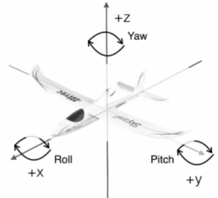
• Attitude indicator: also known as an artificial horizon. Shows the aircraft’s relation to the hori-zon. From this the pilot can tell whether the wings are level (roll, Fig. 1) and if the aircraft nose is pointing above or below the horizon (pitch, Fig. 1).
• Turn indicator: This instrument includes the Turn-and-Slip Indicator and the Turn Coordina-tor, which indicate rotation about the longitudinal axis.
• Heading indicator: displays the aircraft’s heading with respect to magnetic north when set with a compass.
2.2 Flight Control
One time the pilot knows the flight situation through on-board instruments, he must take decisions and ap-ply control commands(actions). Thereby accurately correcting the trajectory. For flight control, the pilot has 3 types of controllers. Generally, these controllers are in much type of aircrafts (de l’Aviation Civile., 1992). Description of controllers for our case, are de-scribed below:
• Yoke: has the function of controlling in both pitch and roll (Fig. 1).
Figure 1: Definition of aircraft body axes.
1. Pitch controller: When the yoke is pulled back the nose of aircraft rises and when it is pulled forward the nose descend.
2. Roll controller: When the yoke is turned right the aircraft rolls to the right(turning right) and when it is turned left the aircraft rolls to the left(turning left).
• Rudder: also pedal direction. When pilot push left pedal, rudder deflects to the left and when pi-lot push right pedal, rudder deflects to the right. With rudder, pilot can not use it to turn left or turn right. Rudder is important for flight stabilization. • Engine power: When pilot turn on the engine, it
provides propulsion to the aircraft, if necessary. Aircraft control systems are based on integro-differential equations or state-space form (Fossen, 2011). We present another method/solution tackled from the perspective of Artificial Intelligence. Next, we introduce how we can describe the issue by using logical representation.
3 CLASSICAL LOGIC
REPRESENTATION
To describe actions, we use classical logic language L (Propositional or First-Order Logic). In L, we can represent, for example, motor(ti)to say that motor is
active at the time ti. Or altitude(low,ti)to say that
the altitude is decreasing at the time ti. We are in a
logical framework, so it is possible to represent al-most everything we want in a natural way. Classical logic, such as First-Order Logic is monotonous. What it means, A ` w then A [ B ` w. This is, by adding new information or set of formulas to a model, the set of consequences of this model is not reduced. The property of monotony is very important in the world of mathematics, because it allows to describe lemmas previously demonstrated. But this property cannot be
Autonomous Aerial Vehicle - Based on Non-Monotonic Logic
applied to uncertain and incomplete information. But in real world, non-monotonic is presents in many sit-uations, this is, each new information we learn can modify or invalidate previous deductions. A classic example is:“Birds typically fly”. This expression can-not be translated by the formula bird(X) ! f ly(X), which will signify that all birds fly. But, there are ex-ceptions to this rule (i.e. if X = Penguin, by definition a penguin is a bird but he not fly). These exceptions are well known in Artificial Intelligence. In the next table, we represent the actions that pilot can do to cor-rect the trajectory of the glider. We consider a discrete system with three possible actions for each of the con-trollers, except for the motor(which it has two states), resulting 11 states.
Table 1: Possible actions.
Roll: Pitch: yoke(le f t,ti) yoke(pull,ti)
yoke roll(neutral,ti) yoke pitch(neutral,ti)
yoke(right,ti) yoke(push,ti)
Yaw: Propulsion: rudder(le f t,ti) motor(ti)
rudder(neutral,ti) non motor(ti)
rudder(right,ti)
For the first approach, we will explicitly give basic pilot rules. For example, we might say, “the yoke is to the right position at the time t”. We can represent in classical logic: yoke(le f t,ti). We use this
nota-tion: var = variometer, ther= thermal, alt = altitude, non ther = non thermal, srh th = searching thermal. A set of rules is explicitly given:
var(up,ti)^ non motor(ti)! ther(ti+1) (1)
batt(low,ti)^ alt(low,ti)! land(ti+1) (2)
non ther(ti)^ alt(low,ti)! land(ti+1) (3)
non ther(ti)^ alt(low,ti)! srh th(ti+1) (4)
non motor(ti)^ var(up,ti)^
turn(le f t,ti)! yoke(right,ti+1) (5)
non motor(ti)^ var(up,ti)^
turn(right,ti)! yoke(le f t,ti+1) (6)
var(up,ti)^ non motor(ti)! alt(up,ti+1) (7)
batt(low,ti)^ non motor(ti)! alt(down,ti+1) (8)
motor(ti)^ yoke(pull,ti+1)! alt(up,ti+1) (9)
Intuitively, we can say,“the variometer is in-creasing at the time t”, in logical representation is: var(up,ti). It is of course possible to add
oth-ers rules(Aeronautics Legislation) to take into ac-count relations between the real scenario and our
logical system. These logical formulations be-fore presented, are problematic because there is a conflict. If for example we have a set of for-mulas: F = {var(up,ti),non motor(ti),batt(low,ti)},
and now, we infer (rule 7 and 8) F: alt(up,ti+1)and
alt(down,ti+1), which is a contradiction. To solve this
conflict, we use non-monotonic logic, more specifi-cally, the default logic.
3.1 Definition of Non-monotonic Logic
It is a family of formal logic devised to capture and represent inference, reserving the right to retract de-ductions when new information is added. The first works in the field of non-monotonic logics began with the realization to precise characterization of defeasi-ble reasoning. Among the pioneers of the field in the late 1970’s were J. McCarthy (McCarthy, 1980; McCarthy, 1986), D. McDermott and J. Doyle, and R. Reiter(Reiter, 1980). Deriving in different non-monotonic logics(Somb´e, 1990; Suchenek, 2006; Delgrande and Schaub, 2005; Delgrande and Schaub, 2003) reasoning: default reasoning(Reiter, 1980), au-toepistemic reasoning, reasoning in the presence of contradictory information, counterfactual reasoning, priority reasoning, and negative reasoning(El-Azhary et al., 2002).
3.2 Definition of Default Logic
A default theory T consists of a set of facts W , which are formulas of First-Order logic and a set of defaults D, which are rules of inference (Re-iter, 1980; Grigoris, 1999; Lukaszewicz, 1988; Lif-schitz, 1999). The main representational tool is that of a default rule, or simply a default. A default is an inference rule of the form: A(X) : B(X)
C(X) , where A(X),B(X),C(X) are well-formed formulas (First-Order Logic). Where X = (x1,x2,x3, ...,xn)as a
vec-tor of free variables(non-quantified). A(X) are the prerequisites, B(X) are the justifications and C(X) are the consequent. Intuitively, a default means:“if A(X) is true, and there is no evidence that B(X) might be false, then C(X) can be true”. Default rules are used to create extensions. These can be contemplated as a set of inferences. It is named normal default, if B(X) = C(X).
3.3 Definition of Extension
When defaults are calculated, the number of formu-las inferred in the knowledge base W increase. An extension of the default theoryD = (D,W) is a set E
of logical formulas(Reiter, 1980). An extension must to verify following property: If d is a default of D, whose the prerequisite is in E, without the negation of its justification is not in E, then the consequent of d is in E. Formally, E is an extension ofD if and only if:
• E = [•i=0Eiwith:
• E0=W and for i 0
Ei+1=T h(Ei)[{C(X)|A(X) : B(X)C(X) 2 D, A(X) 2
Eiand ¬B(X) 62 E}
where T h(Ei)is the set of formulas derived from
Ei. The previous definition is difficult to apply in
practice. Because ¬B 62 E supposes E is known, but E is not yet calculated. In the case of normal defaults(B(X) = C(X)), an extension is defined: E is an extension ofD if and only if:
• E = [•i=0Eiwith:
• E0=W and for i 0
Ei+1=T h(Ei)[{C(X)|A(X) : C(X)C(X) 2 D, A(X) 2
Eiand ¬C(X) 62 Ei}
where T h(Ei)is the set of formulas derived from
Ei. According to Reiter(Reiter, 1980), if all defaults
are normal, it exists at least one extension. Extensions are defined by a fixed point.
4 DEFAULT LOGIC
REPRESENTATION
Flight rules are described by a set of rules. For exam-ple, alt(up) is a positive literal, means that the glider increases in altitude. The dynamic of the system can be described by var(up,t), which means that the var-iometer at the time t is increasing. Clauses are the simplest type of formula. Formally, a clause is a dis-junction of literals l1_ l2_ l3_ ... _ ln. A Horn clause
is a clause with a maximum of one positive literal. It’s a formula defined as ( f1^ f2^ f3^ ... ^ fi)! g,
where fiand g are positive literal. Similarly, the
for-mula defined as ¬( f1^ f2^ f3^ ... ^ fi)is equivalent
to the negative Horn clause(literals can not be true si-multaneously). In default logic, we have two sets of rules. The set D of defaults and the set W of facts. For example, set W : batt(good) that is an elementary fact says that battery has sufficient power. And set D: batt(good) : motor(on)
motor(on) , this default rule means, “Generally when battery has sufficient power, motor is on”. Therefore, we introduce normal defaults rep-resentation.
4.1 Set of Default [D]
The set of inference rules D describes possibles ac-tions, including incomplete and contradictory infor-mation. It represents a normal default. By using de-fault logic, the rules(7, 8 and 9 in section 3) above could be expressed intuitively as:
7’ If var(up,ti),non motor(ti) are true, and if
alt(up,ti+1)is not contradictory, then alt(up,ti+1)
is true.
8’ If batt(low,ti),non motor(ti) are true, and
if alt(down,ti+1) is not contradictory, then
alt(down,ti+1)is true.
9’ If motor(ti),yoke(pull,ti+1) are true, and if
alt(up,ti+1)is not contradictory, then alt(up,ti+1)
is true.
Taking the rules(7’,8’ and 9’), default logic repre-sentation is presented, d = A(X) : C(X)
C(X) .
d1=var(up,ti)^ non motor(ti): alt(up,ti+1) alt(up,ti+1)
d2=batt(low,ti)^ non motor(ti)alt(down,t : alt(down,ti+1) i+1)
d3=motor(ti)^ yoke(pull,ti+1alt(up,t ): alt(up,ti+1) i+1)
4.2 Set of Default [W]
The set of facts W represents accurate and non-revisable information. The facts are formulas always true. Unary clauses are elementary source of informa-tion. We can use such a clause to represent a mutual exclusions. For example, taking the rule “The motor-glider can not search a thermal and land at the same time”, 8t,¬(glider(search ther,ti)^glider(land,ti)).
4.3 Extensions Calculation
To illustrate the use of the default logic, we give in the next paragraph an exam-ple of calculation by using the Algorithm 1. W = motor(o f f ,t),alt(down,t),var(down,t), batt(good,t). With: 8t,¬(glider(land,t + 1) ^ glider(srh th,t + 1)). Intuitively, W means that glider has not using motor(as propulsion), its altime-ter is decreasing, its variomealtime-ter is decreasing and its battery has sufficient power at time ti, respectively.
The Algorithm 1 presented below is written in Prolog. Our algorithm calculates the extensions. As the clauses are Horn clauses, and as the de-faults are normal. The results obtained using a set D(subsection 4.1) and a set W (subsection 4.2)
Autonomous Aerial Vehicle - Based on Non-Monotonic Logic
are: E0={glider(srh th,t),motor(o f f ,t),alt(down,t), var(down,t),batt(good,t)}
d0= alt(down,t) ^ var(down,t) : glider(srh th,t + 1)glider(srh th,t + 1) (10) E1 = {glider(land,t),motor(o f f ,t),alt(down,t), var(down,t),batt(good,t)}
d1= alt(down,t) ^ var(down,t) : glider(land,t + 1) glider(land,t + 1)
(11)
We can see that W uses a rule that says glider(srh th,t +1) and glider(land,t +1) are mutu-ally exclusive. According to this rule, it is not pos-sible to use d0 and d1 at the same time. If d0 is
used, glider(land,t + 1) is added to the extension, then mutual exclusive will cancel d1. In the same
way, if d1 is used we cannot use d0. We obtain 2
contradictory extensions(solutions). In the first one there is glider(srh th,t + 1)(The glider can search a thermal at time t + 1) and the other one there is glider(land,t + 1)(The glider can land at time t + 1). In this way, the conflict shown in section 3 is resolved.
Data: E = /0 (Set of extensions E is empty) Result: E = [N
i=0Ei
Initialization; CalculExtension(E);
while there is a default (A(X) : C(X))/C(X) that has not yet been inspecteddo
Select the default D; Verify A(X) are true;
Verify C(X) is consistent with W ; Add C(X) to W ;
end
Backtracking(deleting C(X) added to W ); CalculExtension(E);
Algorithm 1: Calculation of extensions. In practice, the choose of extension corresponds a weight to each default considering its importance. An example could be, to search a thermal is more pri-ority (more weight) than land(Toulgoat, 2011; Grig-oris, 1999). These decisions are based on weighted product model: P(AK/AL) =’nj=1(aK j/aL j)wj for
K,L = 1,2,3,...,m. Using this method we ponder ex-tensions then we select the best response.
5 APPLICATION
In this section we present the practical application and current work. In the Fig. 2 shows the different parts of our discrete model. On the left side in the
Figure 2: Operating diagram.
Fig. 2, we have the Input such as data, which acces-sible from electronic devices. Different data are air-speed, altitude, angles of pitch and roll, etc. Block Set of facts[W] accepts data for knowledge representa-tion. Next, Calculation of extensions and Action cho-sen blocks are the reprecho-sentation of our Algorithm 1. Finally, we have Output such as an action to apply. Certainly to the servo-motors to control pitch, roll and eventually yaw(Fig. 1). These actions will be applied to a glider(reduced model,Sky Scout version R2GO). Our glider is equipped with a motor, in case he needs desperate increase his altitude or find a rising air. On the other hand, the motor-glider is equipped with an on-board computer. Prolog has been installed and sensors have been successfully implemented. The Algorithm 2 is presented which represents the blocks of Pre-processing and Set of facts[W], described in Fig. 2. Tsis sampling time in seconds.
Data: From electronic device [I] Result: Set of facts [W]
Initialization of electronics devices; while Ts=1do
CaptureData(I) from electronics devices; DescriptionFacts(W) by following our
syntax; end
Algorithm 2: Knowledge representation.
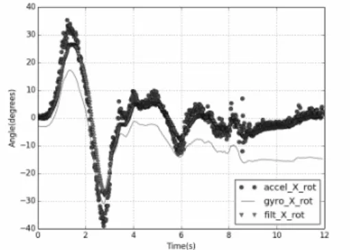
Data are from the Inertial Measurement Unit(IMU). An electronics device which collects angular velocity and linear acceleration data. Usually a combination of accelerometers and gyroscopes, sometimes also magnetometers. An IMU works by detecting changes in rotational attributes like pitch, roll and yaw, using gyroscopes. On the other hand, signal processing techniques(Fig. 2) has tremendous potential in the information fusion theory and in practical applications. Important part because is the process of integration of multiple data for knowledge representation. The acquisition of knowledge is defined by rules(subsection 4.3). In Fig. 3, rotation on the X axis is represented, the combination of accelerometer(circle) and gyroscope(line) data, the result is a signal(triangle) that we use to describe the world.
Figure 3: Data fusion.
6 CONCLUSIONS
In our approach, an algorithm based on default logic is proposed to tackle contradictory information. Flight rules are uncertain, because many situations in-clude contradictions and we have to verify them. Fur-thermore, aeronautics legislation is based on contra-dictory rules. Non-monotonic logic has a great advan-tage in these kind of cases. We presented a simulation of a glider searching thermals. The results provide the basis for an autonomous motor-glider. We pre-sented short and simple Prolog programs. For initial tests(around 100 rules), we calculate all extensions in a short time. The calculation takes 1956600 Logical Inferences Per Second (LIPS) and 0.049 seconds of central processing unit (CPU) time on a MacBook. Discrete model is currently being developed for test-ing. Sensors and on-board computer set-up is com-plete. We configured an embedded system, installing prolog (SWI-Prolog). We also have installed an em-bedded sensor with 10 degrees of freedom (DOF). To capture data, such as altitude, acceleration, pitch, roll, yaw, etc. for knowledge representation. More rules are currently incorporated to take into account the aeronautics legislation and solar power management for on-board systems.
ACKNOWLEDGEMENTS
We thanks to the Secretariat of Energy (SENER) through the Mexican National Council for Sci-ence and Technology (CONACYT)[grant number 581317/412566] for their support.
REFERENCES
Chandra, A. (2010). Synergy between biology and systems resilience. Scholars’ Mine.
de l’Aviation Civile., D. G. (1992). Manuel du pilote d’avion Vol `a vue.
Delgrande, J. and Schaub, T. (2003). On the relation be-tween reiter’s default logic and its (major) variants. Seventh European Conference on Symbolic and Quan-titative Approaches to Reasoning with Uncertainty (ECSQARU).
Delgrande, J. and Schaub, T. (2005). Expressing default logic variants in default logic. Journal of Logic and Computation.
Doncescu, A. and Siegel, P. (2015). DNA Double-Strand Break-Based Nonmonotonic Logic. Computa-tional Biology, Bioinformatics and Systems Biology. Elservier.
El-Azhary, Edrees, A., and Rafea, A. (2002). Diagnostic expert system using non-monotonic reasoning. Expert Systems with Applications, pages 137–144.
Fossen, T. (2011). Mathematical models for control of air-craft and satellites. Department of Engineering Cy-bernetics, NTNU.
Goerger, S., Madni, A., and Eslinger, O. (2014). Engineered resilient systems: A dod perspective. Procedia Com-puter Science, pages 865–872.
Grigoris, A. (1999). A tutorial on default logics. ACM Com-puting Surveys.
Le, T., Doncescu, A., and Siegel, P. (2013). Utilization of default logic for analyzing a metabolic system in dis-crete time. ICCSA.
Lifschitz, V. (1999). Success of default logic. Logical Foun-dations for Cognitive Agents: Contributions in Honor of Ray Reiter.
Lukaszewicz, W. (1988). Consideration on default logic: an alternative approach. Comput. Intell.
McCarthy, J. (1980). Circumscription - a form of non-monotonic reasoning. Artificial Intelligence. McCarthy, J. (1986). Applications of circumscription to
for-malizing common-sense knowledge. Artificial Intelli-gence.
Reiter, R. (1980). A logic for default reasonig. Artificial Intelligence, pages 81–132.
Somb´e, L. (1990). Reasoning under incomplete information in artificial intelligence: a comparison of formalisms using a single example. John Wiley and Sons Inc. Suchenek, M. (2006). On undecidability of non-monotonic
logic. Studia Informatica.
Toulgoat, I. (2011). Mod´elisation du comportement humain dans les simulations de combat naval. PhD thesis, Laboratoire SNC/DCNS.
Toulgoat, I., Siegel, P., and Doncescu, A. (2011). Mod-elling of submarine navigation by nonmonotonic logic. BWCCA.
Autonomous Aerial Vehicle - Based on Non-Monotonic Logic