HAL Id: tel-01795135
https://pastel.archives-ouvertes.fr/tel-01795135
Submitted on 18 May 2018
HAL is a multi-disciplinary open access archive for the deposit and dissemination of sci-entific research documents, whether they are pub-lished or not. The documents may come from
L’archive ouverte pluridisciplinaire HAL, est destinée au dépôt et à la diffusion de documents scientifiques de niveau recherche, publiés ou non, émanant des établissements d’enseignement et de
Modeling of bending-torsion couplings in active-bending
structures : application to the design of elastic gridshells
Lionel Du Peloux de Saint Romain
To cite this version:
Lionel Du Peloux de Saint Romain. Modeling of bending-torsion couplings in active-bending struc-tures : application to the design of elastic gridshells. Materials. Université Paris-Est, 2017. English. �NNT : 2017PESC1209�. �tel-01795135�
ELASTIC
GRIDSHELL
2017
Ph
D
Lio
ne
ld
u
Pe
lo
ux
EL
A
ST
IC
G
R
ID
SH
EL
L
Modeling of bending-torsion couplings in active-bending structures
APPLICATION TO THE DESIGN OF ELASTIC GRIDSHELLS
An elastic gridshell is a freeform structure, gener-ally doubly curved, but formed out through the re-versible deformation of a regular and initially flat structural grid. Building curved shapes that may seems to offer the best of both worlds : shell struc-tures are amongst the most performant mechan-ically speaking while planar and orthogonal con-structions are much more efficient and economic to produce than curved ones. This ability to “form a form” efficiently is of peculiar importance in the current context where morphology is a predomi-nant component of modern architecture, and en-velopes appear to be the neuralgic point for build-ing performances.
The concept was invented by Frei Otto, a Ger-man architect and structural engineer who devoted
many years of research to gridshells. In 1975 he designed the Multihalle of Mannheim, a 7500 m2
wooden shell which demonstrated the feasibility of this technology and made it famous to a wide au-dience. However, despite their potential, very few projects of this kind were built after this major real-ization. And for good reason, the resources com-mitted at that time cannot guarantee the replicabil-ity of this experiment for more standard projects, especially on the economic level. Moreover, the technics and methods developed by Otto's team in the 1960s have mostly fall into disuse or are based on disciplines that have considerably evolved. New materials, such as composite materials, have
recently emerged. They go beyond the limita-tions of conventional materials such as timber and offer at all levels much better technical perfor-mances for this kind of application. Finally, it should be noted that the regulatory framework has also deeply changed, bringing a certain rigidity to the penetration of innovations in the building indus-try. Therefore, the design of gridshells arises in new terms for current architects and engineers and comes up against the inadequacy of existing tools and methods.
In a first part, we deliver a thorough review of this topic and we present in detail one of our main achievements, the ephemeral cathedral of Créteil, built in 2013 and still in service. In a second part, we develop an original discrete beam element with
a minimal number of degrees of freedom adapted to the modeling of bending and torsion inside grid-shell members with anisotropic cross-section. En-riched with a ghost node, it allows to model more accurately physical phenomena that occur at con-nections or at supports. Its numerical implemen-tation is presented and validated through several test cases. Although this element has been devel-oped specifically for the study of elastic gridshells, it can advantageously be used in any type of prob-lem where the need for an interactive computation with elastic rods taking into account flexion-torsion couplings is required.
In this thesis, which marks an important step in a personal research adventure initiated in 2010, we try to embrace the issue of the design of elastic gridshells in all its complexity,
THE DESIGN OF ELASTIC GRIDSHELLS
Modeling of bending-torsion couplings
in active-bending structures
application to
THESE DE DOCTORAT
Modeling of bending-torsion couplings in active-bending structures. Application to the design of elastic gridshells.
Invité Bernard VAUDEVILLE
Cyril DOUTHE
Jean-François CARON
Examinateurs Alberto PUGNALE
Carlos LÁZARO
Rapporteurs Sébastien NEUKIRSH
Président Bernard MAURIN
Date 20 décembre 2017
Lieu Ecole Nationale des Ponts et Chaussées
Auteur Lionel DU PELOUX DE SAINT ROMAIN
Spécialité Structures et Matériaux
Ecole Doctorale Science, Ingénierie et Environnement
Laboratoire UMR Navier
“Quia nominor leo.”
À Jacques & Christiane, Mes grands-parents bien-aimés.
Tu ne peux vivre Que de cela que tu transformes, Et dont un peu chaque jour, Puisque tu t’échanges contre, Tu meurs. ķAntoine de Saint-Exupéry
PRÉFACE
Si pour une raison quelconque il ne devait subsister qu’une unique page de ce manuscrit, j’aimerais autant que ce soit celle-là. Et qu’alors, seuls vivent les quelques mots de gratitude qui suivent pour les personnes qui m’ont accompagné sur ce chemin de fortune ; chemin initié en 2010 au sortir de l’Ecole Centrale et qui m’a conduit à présenter cette thıse. Plus que la perspective d’une éventuelle contribution scientifique, c’est avant tout un certain goût pour la liberté d’aller et venir qui m’a animé ; cette mĝme liberté que je quĝte à travers mes sorties en montagne.
L’une de mes plus grandes chances aura été de pouvoir d’un mĝme mouvement concevoir et bâtir des gridshells, objets de cette étude, sans quoi ma compréhension du sujet serait restée beaucoup plus superficielle. Par ailleurs, les joies simples glanées sur les chantiers de ces projets atypiques ĸ je pense en particulier aux séminaires Construire le Courbe avec des étudiants, à la construction du pavillon Solidays en 2011 avec des bénévoles et plus encore à la réalisation de la cathédrale éphémıre de Créteil en 2013 avec des paroissiens ĸ furent pour moi sans égales avec celles, plus rares, reçues dans mon quotidien quelque
PRÉFACE
peu taciturne de chercheur.
Chers Jean-François et Olivier, merci de m’avoir accueilli au sein de l’équipe MSA et d’avoir su me trouver une place sur mesure au fil de ces années. Merci pour la liberté que vous m’avez procurée et pour la confiance que vous m’avez accordée dans la conduite de mon travail de recherche, mais aussi dans certains projets annexes (e.g. solidays, thinkshell, booby). L’équipe s’est étoffée de nouveaux talents et la construction de cette dynamique vous doit beaucoup : vous savez catalyser notre enthousiasme.
Cher Cyril, merci de ce compagnonnage de quelques années. Je me souviens de t’avoir (un peu) connu avant mĝme de te rencontrer, par l’étude de ta thıse ! J’ai pris beaucoup de plaisir à travailler avec toi au cours de ces années et il en est sorti de beaux projets. Merci plus particuliırement pour les responsabilités que tu m’as confiées dans le sémi-naire Construire le Courbe et d’avoir accepté d’en chambouler le programme pédagogique d’année en année. Merci également pour ton écoute, tes conseils et ton précieux travail de relecture tout au long de l’élaboration de ce manuscrit. Sa qualité s’en est trouvée grandement améliorée.
Cher Bernard, nous avons partagé sans doute quelques angoisses sans nous le dire, mais cette cathédrale de Créteil restera pour moi un projet mémorable et intense. Merci de m’avoir fait confiance pour développer ce projet et d’avoir été présent dans les moments critiques de cette aventure. Plus qu’un bagage technique, j’ai appris durant ces trois années chez T/E/S/S une certaine façon de résoudre des problımes, de chercher des solutions sans me décourager. Et cela m’a beaucoup profité dans mon travail de thıse et me restera acquis pour les années à venir. Merci donc à toi ainsi qu’à Tom et à Matt pour ce qui m’a été transmis au bureau.
Cher Frédéric, avec toi j’ai manié la clef dynamométrique comme jamais ! Ton travail a grandement contribué à la réussite des projets Solidays et Créteil. Tu es toujours disponible pour trouver une solution, bricoler un montage, faire fonctionner un four ou une fraise, imprimer une piıce en 3D, réparer des gouttiıres, partager ton analyse, donner un conseil, etc. J’ai beaucoup appris du travail que tu as initié au cours de ta thıse avec l’aide de Baptiste et dans la continuité duquel je m’inscris. Merci pour tout cela.
Je tiens à remercier Sébastien Neukirch et Carlos Lázaro, rapporteurs, qui par leurs re-marques et conseils avisés ont contribué à améliorer la qualité de ce mémoire de thıse. Je remercie également les autres membres du jury ĸ Bernard Maurin son président, Alberto Pugnale, Jean-François Caron, Cyril Douthe et Bernard Vaudeville ĸ pour leur écoute et leurs remarques de qualité. C’est toujours une grande chance de bénéficier d’une relec-ture rigoureuse de son propre travail par des personnes d’expérience ; et cela permet d’en
PRÉFACE
regarder avec plus de lucidité les solidités comme les faiblesses.
Merci chers Marine, Romain(s), Robert, Gilles, Arthur, Ioanis, Marie, Tristan, Pierre(s), Victor, Philippe, Vianney Ĵ co-bureaux ou collıgues de travail plus ponctuels, notamment lors des semaines Construire le Courbe, pour les petits mots échangés ça et là lors d’un café ou d’un repas et pour votre enthousiasme quotidien. Merci Marie-Françoise, Christophe, Anne, Gilles, Géraldine, Alain, Hocine, pour l’aide constante apportée au cours de ces années passées au laboratoire.
Enfin, je ne serais pas allé au bout de ce travail sans le soutien des nombreux parents et amis qui m’entourent quotidiennement. A vous tous, merci de votre soutien et de votre patience lors de ces derniers mois, avec une mention toute spéciale pour Blandine qui m’a gratifié de son affection indéfectible et a supporté mes horaires incongrus.
Lyon, le 4 novembre 2017 Lionel du Peloux
ABSTRACT
An elastic gridshell is a freeform structure, generally doubly curved, but formed out through the reversible deformation of a regular and initially flat structural grid. Building curved shapes that may seems to offer the best of both worlds : shell structures are amongst the most performant mechanically speaking while planar and orthogonal constructions are much more efficient and economic to produce than curved ones. This ability to “form a form” efficiently is of peculiar importance in the current context where morphology is a predominant component of modern architecture, and envelopes appear to be the neuralgic point for building performances.
The concept was invented by Frei Otto, a German architect and structural engineer who devoted many years of research to gridshells. In 1975 he designed the Multihalle of Mannheim, a 7500 m2 wooden shell which demonstrated the feasibility of this
technol-ogy and made it famous to a wide audience. However, despite their potential, very few projects of this kind were built after this major realization. And for good reason, the resources committed at that time cannot guarantee the replicability of this experiment
ABSTRACT
for more standard projects, especially on the economic level. Moreover, the technics and methods developed by Otto’s team in the 1960s have mostly fall into disuse or are based on disciplines that have considerably evolved. New materials, such as composite mate-rials, have recently emerged. They go beyond the limitations of conventional materials such as timber and offer at all levels much better technical performances for this kind of application. Finally, it should be noted that the regulatory framework has also deeply changed, bringing a certain rigidity to the penetration of innovations in the building in-dustry. Therefore, the design of gridshells arises in new terms for current architects and engineers and comes up against the inadequacy of existing tools and methods.
In this thesis, which marks an important step in a personal research adventure initiated in 2010, we try to embrace the issue of the design of elastic gridshells in all its complexity, addressing both theoretical, technical and constructive aspects. In a first part, we deliver a thorough review of this topic and we present in detail one of our main achievements, the ephemeral cathedral of Créteil, built in 2013 and still in service. In a second part, we develop an original discrete beam element with a minimal number of degrees of freedom adapted to the modeling of bending and torsion inside gridshell members with anisotropic cross-section. Enriched with a ghost node, it allows to model more accurately physical phenomena that occur at connections or at supports. Its numerical implementation is presented and validated through several test cases. Although this element has been devel-oped specifically for the study of elastic gridshells, it can advantageously be used in any type of problem where the need for an interactive computation with elastic rods taking into account flexion-torsion couplings is required.
Keywords : gridshell, form-finding, active-bending, free-form, torsion, elastic rod, cou-pling, fibreglass, composite material.
RÉSUMÉ
Les structures de type gridshell élastique permettent de réaliser des enveloppes courbes par la déformation réversible d’une grille structurelle réguliıre initialement plane. Cette capacité à “former la forme” de façon efficiente prend tout son sens dans le contexte actuel où, d’une part la forme s’impose comme une composante prédominante de l’architecture moderne, et d’autre part l’enveloppe s’affirme comme le lieu névralgique de la performance des bâtiments.
Fruit des recherches de l’architecte et ingénieur allemand Frei Otto dans les années 1960, elles ont été rendues populaires par la construction de la Multihalle de Mannheim en 1975. Cependant, en dépit de leur potentiel, trıs peu de projets de ce type ont vu le jour suite à cette réalisation emblématique qui en a pourtant démontré la faisabilité à grande échelle. Et pour cause, les moyens engagés à l’époque ne sauraient assurer la reproductibilité de cette expérience dans un contexte plus classique de projet, notamment sur le plan éco-nomique. Par ailleurs, les techniques et les méthodes développées alors sont pour la plus part tombées en désuétude ou reposent sur des disciplines scientifiques qui ont
considéra-RÉSUMÉ
blement évoluées. Des matériaux nouveaux, composites, ont vu le jour. Ils repoussent les limitations intrinsıques des matériaux usuels tel que le bois et offrent des performances techniques bien plus intéressantes pour ce type d’application. Enfin, notons que le cadre réglementaire a lui aussi profondément muté, apportant une certaine rigidité vis-à-vis de la pénétration des innovations. Ainsi la conception des gridshells se pose-t-elle en des termes nouveaux aux architectes et ingénieurs actuels et se heurte à l’inadéquation des outils et méthodes existant.
Dans cette thıse, qui marque une étape importante dans une aventure de recherche person-nelle initiée en 2010, nous tentons d’embrasser la question de la conception des gridshells élastiques dans toute sa complexité, en abordant aussi bien les aspects théoriques que tech-niques et constructifs. Dans une premiıre partie, nous livrons une revue approfondie de cette thématique et nous présentons de façon détaillée l’une de nos principales réalisation, la cathédrale éphémıre de Créteil, construite en 2013 et toujours en service. Dans une seconde partie, nous développons un élément de poutre discret original avec un nombre minimal de degrés de liberté adapté à la modélisation de la flexion et de la torsion dans les gridshells constitués de poutres de section anisotrope. Enrichi d’un noeud fantôme, il per-met de modéliser plus finement les phénomınes physiques au niveau des connexions et des appuis. Son implémentation numérique est présentée et validée sur quelques cas tests. Bien que cet élément ait été développé spécifiquement pour l’étude des gridshells élastiques, il pourra avantageusement ĝtre utilisé dans tout type de problıme où la nécessité d’un calcul interactif avec des tiges élastiques prenant en compte les couplages flexion-torsion s’avıre nécessaire.
Keywords : gridshell, form-finding, active-bending, free-form, torsion, elastic rod, cou-pling, fibreglass, composite material.
CONTENTS
Préface
xiAbstract (English/Français)
xvContents
xixList of Figures
xxixList of Tables
xxxviiCONTENTS
Introduction
1■ Part I : Elastic gridshells ■
1
Elastic gridshells
9 1.1 Introduction 9 Overview 9 Contributions 10 1.2 Definition 10 Erection process 10 Structural typology 12Material flexibility for structural rigidity 12
1.3 Built elastic gridshells : a review 12
The beginnings : from the first prototype to the German Pavilion 14 Mannheim Multihalle : the completion of a decade of research 18 The dry period : 25 years from Mannheim to Hannover 22 The signs of a renewal : Dorset and Doncaster 22 The renewal : Hannover, Downland and Savill 24 Gridshell in composite materials : a new perpective 34 Flourishing timber gridshell pavilions 38
Latest experiments 43
1.4 Research works on elastic gridshells : a review 44
Mechanics 44 Geometry 46 Material 47 Technology 47 1.5 Conclusion 48
2
Ephemeral cathedral
55 2.1 Introduction 55 Overview 56CONTENTS
Contributions 56
2.2 Project overview 57
Context and challenges 57
Architectural considerations on the form 59
Placing of the building on the site 59
Entrance 60
Daylight 60
Technical description 64
2.3 Construction process 70
Assembly of the grid 70
Deformation of the grid 70
Bracing of the grid 70
Covering of the gridshell 73
2.4 Structural design 73
Overall design process 73
3D modelling of the intended shape 74
Meshing the surface 75
Form-finding and bending prestress 78
As-built geometry 80
Structural analysis 81
2.5 Designing with GFRP materials 81
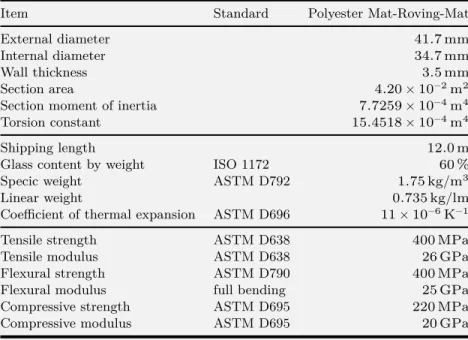
Properties of the tubes 81
Codes for composite materials 83
Flexural strength of the tubes 84
Partial safety factors 84
2.6 Construction details 86
The swivel coupler 86
The sleeve system 92
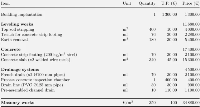
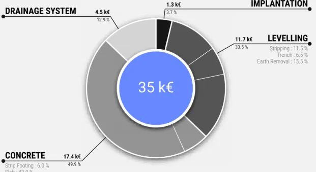
Foundations 98 The membrane 98 2.7 Hygrothermal behavior 101 Temperature 101 Moisture 104 2.8 Cost analysis 104
Overall cost for the client 104
Cost details for the building 107
CONTENTS
2.9 Conclusions 115
■ Part II : Kirchhoff beam model ■
3
Geometry of discrete curves
1233.1 Introduction 123 Overview 124 Contributions 125 Related work 125 3.2 Parametric curves 126 Definition 127 Regularity 127 Reparametrization 127 Natural parametrization 128 Curve length 128
Arc length parametrization 128
3.3 Frenet trihedron 129
Tangent vector 129
Normal vector 130
Binormal vector 131
Osculating plane 132
3.4 Curves of double curvature 132
First invariant : the curvature 133
Second invariant : the torsion 136
Fundamental theorem of space curves 137
Serret-Frenet formulas 137
3.5 Curve framing 139
Moving frame 139
Adapted moving frame 143
Rotation-minimizing frame 144
Parallel transport 144
Frenet frame 145
Bishop frame 147
CONTENTS 3.6 Discrete curves 152 Definition 153 Regularity 154 Parametrization 155 3.7 Discrete curvature 156
Definition from osculating circles 156
Benchmarking : sensitivity to non uniform discretization 161 Benchmarking : accuracy in bending energy representation 164
3.8 Discrete tangent vector 170
Circumscribed case 170
Inscribed case 173
3.9 Discrete parallel transport 176
The rotation method 177
The double reflexion method 177
3.10 Conclusion 179
4
Elastic rod : variational approach
1834.1 Introduction 183
Overview 184
Contributions 184
Related work 185
4.2 Kirchhoff rod 186
Description of the motion 186
Inextensibility assumption 187
Euler-Bernoulli assumption 188
Motion of the material frame 188
Material curvatures and twist 189
Material constitutive equations 190
Elastic energy 190
4.3 Curve-angle representation 191
Definition of the representation 192
Measurement of the material twist 193
CONTENTS
4.4 Definition of the variational problem 194
Calculus of variations 194
Prerequisite for the computation of energy gradients 196 Coupling between bending and torsion 196
Quasistatic assumption 196
4.5 Energy gradient with respect to𝜃: twisting moment 197
Derivative of material directors with respect to𝜃 197 Derivative of the material curvatures vector with respect to𝜃 197
Computation of the twisting moment 198
4.6 Energy gradient with respect to𝒙: internal forces 200
Derivative of material directors with respect to𝒙 200 Derivative of the vector of material curvatures with respect to𝒙 208 Computation of the forces acting on the centerline 209
4.7 Shear force acting on the rod 213
4.8 Discussion 213
4.9 Conclusion 214
5
Elastic rod : equilibrium approach
2195.1 Introduction 219
Overview 220
Contributions 221
Related work 221
5.2 Introduction to the special Cosserat theory of rods 222
Description of the motion 223
Time evolution 229
Force and moment strains 230
Parametrization of the centerline 231
To go further 232
5.3 Kirchhoff theory of rods 232
Description of the motion 233
Reparametrization 236
Force and moment strains 237
Balance of momentum 239
Equations of motion 246
CONTENTS
Deformation of cross-sections 248
Strain tensor 250
Stress tensor 250
Constitutive equations for internal forces and moments 250
Discussion 252
5.4 Summary of Kirchhoff theory 253
5.5 Geometric interpretation of Kirchhoff's equations 256
influence of the curvature (𝜅) 259
influence of the first material curvature (𝜅1) 261 Influence of the second material curvature (𝜅2) 265
5.6 Conclusion 267
6
Numerical Model
271 6.1 Introduction 271 Overview 272 Contributions 273 Related works 2736.2 Discrete beam element 275
Description of the element 277
Modeling of discontinuities 279
Matrix notation 280
Discrete extension and axial force 281
Discrete curvature and bending moment 281 Discrete rate of twist and twisting moment 285
Discrete shear force 286
Interpolation of the internal forces and moments 288
6.3 Dynamic Relaxation 290
Overview of the procedure 291
Resultants acting on a particle 291
Equations of motion 293
Explicit time integration 294
Damping 297
Convergence 300
Stability and critical damping 302
CONTENTS
6.4 Enriching the model 309
Support condition 309
Connection 310
6.5 Software 311
Architecture of the software 311
Structure of the algorithm 312
Key aspects 312 Performance 315 6.6 Test case 317 Constrained arch 317 6.7 Conclusion 323
Conclusion
327■ Part III : Appendix ■
A
Review of built elastic gridshells
337B
Calculus of variations
341B.1 Introduction 341
B.2 Spaces 341
Normed space 341
Inner product space 342
Euclidean space 342 Banach space 342 Hilbert space 343 B.3 Derivative 343 Fréchet derivative 343 Gâteaux derivative 344 Useful properties 346 Partial derivative 346
CONTENTS B.4 Gradient vector 347 B.5 Jacobian matrix 347 B.6 Hessian 348 B.7 Functional 348
C
Parabolic interpolation
351 C.1 Introduction 351C.2 Lagrange interpolating polynomial 352
C.3 Reparametrization 352 C.4 Characteristic values 353 C.5 Extremum value 354 ■ ■ ■
Index of notation
355Bibliography
359LIST OF FIGURES
1.1 Forming process of the gridshell of Mannheim, Germany 11
a Assembly of the timber grid 11
b Deformation of the grid 11
c Final shape of the lattice 11
d Roofing with a membrane 11
1.2 Known elastic gridshells built by the past 13
1.3 Steel gridshell built in 1962 in Berkeley, USA 15
a Steel lattice 15
b Knot detail 15
1.4 Timber gridshell built in 1962 in Essen, Germany 15
1.5 Timber gridshell built in 1967 in Montreal, Canada 16
1.6 Timber gridshell built in 1975 in Mannheim, Germany 19
a Sky view 19
LIST OF FIGURES
1.7 Roundwood gridshell built in 1995 in Dorset, England 23
a Interior view 23
b Exterior view 23
1.8 Timber gridshells built in 1998 in Doncaster, England 23
a Interior view 23
b Exterior view 23
1.9 Cardboard gridshell built in 2000 in Hannover, Germany 25
a Sky view 25
b Interior view 25
c Knot detail 25
1.10 Timber gridshell built in 2002 in Downland, England 27
a Interior view 27
b Exterior view 27
1.11 Construction stages of the Downland gridshell 28
a Flat grid on scaffold platform 28
b Deformed grid 28
c Triangulated grid 29
d Final structure with cladding 29
1.12 Timber gridshell built in 2002 in Pishwanton, England 31
a Interior view 31
b Exterior view 31
1.13 Timber gridshells built in 1998 in Doncaster, England 31
a Interior view 31
b Exterior view 31
1.14 Timber gridshell built in 2006 in Savill, England 32
a Interior view 32
b Exterior view 32
1.15 Timber gridshell built in 2007 in Kent, England. 32
a Glazing support 32
b Exterior view 32
1.16 GFRP gridshells built in 2006 and 2007 in Noisy-Champs, France 35
a First prototype 2006 35
b Second prototype 2007 35
1.17 Solidays GFRP gridshell built in 2011 in Paris, France 36
1.18 GFRP gridshell built in 2013 in Créteil, France 37
LIST OF FIGURES
b Exterior view 37
1.19 Timber gridshells built by gridshell.it in Italy 39
a Lecce 2010 39
b Toledo 2014 39
1.20 Timber gridshell built in 2013 in San Antonio, USA 39
a Folding skin 39
b Pavilion 39
1.21 Timber gridshell built in 2016 in Montpellier, France 41
a Pavilion 41
b Tensioner 41
1.22 Timber gridshell built in 2016 in Champs-sur-Marne, France 42
a Robotic manufacturing 42
b Timber lattice 42
1.23 Hybrid structural skin built in 2016 in Champs-sur-Marne, France 42
a Interior view 42 b Concrete shell 42 ■ ■ ■ 2.1 Situation map 58 2.2 Architectural sketch 58 2.3 Steel doors 60 a Interior view 60 b Exterior view 60
2.4 Exterior view of the gridshell 61
2.5 Interior view of the gridshell 62
2.6 Key elements of the structural system 65
a Swivel coupler 65
b Sleeve system 65
c Ground anchorage 65
d Lacing rod 65
2.7 Top view of the building 67
2.8 Transversal section of the building 68
2.9 Assembly of the grid 71
LIST OF FIGURES
b Primary grid 71
c Cranes ready to lift the grid 71
2.10 Deformation of the grid 71
a Begining of the deformation 71
b Grid largely deformed 71
c Fixing the grid 71
2.11 Bracing of the grid 72
a Before triangulation 72
b After triangulation 72
2.12 Installation of the membrane 72
a Unpacking the membrane 72
b Pulling the membrane in the grid 72
c The membrane is in place 72
2.13 Benchmarking shapes regarding their curvature 75
2.14 The compass method step by step 77
a Target shape 77
b Domain and trimming surfaces 77
c Secant directrices 77
d Resulting mesh 77
e Trimmed mesh 77
f Final grid 77
2.15 Principle of the compass method 77
2.16 Permanent bending stresses in the structure under self-weight 79
2.17 Reconstruction of the full 3D geometry 80
a Wire frame 80
b Full 3D 80
2.18 Flexural test of the GFRP tubes 85
2.19 Technical drawing of the swivel coupler 87
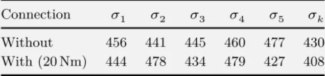
2.20 Influence of the interface layer on the sliding resistance 88
2.21 Influence of the tightening on the sliding resistance 89
2.22 Influence of the temperature on the sliding resistance 90
2.23 Technical drawing of the sleeve system 92
2.24 Design and behavior of the the sleeve system 93
a Solidays 2011 93
b Créteil 2013 93
LIST OF FIGURES
d Plastification threshold 93
2.25 Typical failure modes when testing the sleeve system in traction 95
a Tearing 95
b Contact compression 95
2.26 Typical failure modes of a bolt in a pultruded element 96
a Geometry 96 b Fibres 96 c Cleavage 96 d Tearing 96 e Inclined compression 96 f Contact compression 96
2.27 Tensile test of the pinned connection 97
2.28 Technical drawing of the footing 99
2.29 Weather data at site location during opening hours 102
a Temperature 102
b Solar radiation 102
2.30 Temperature inside the building during opening hours 103
a Without ventilation 103
b With ventilation 103
2.31 Cost allocation for the whole project 105
2.32 Cost allocation per square meter of covered area 106
2.33 Allocation of the man-hours spent by the volunteers 109
2.34 Cost allocation for masonry works 111
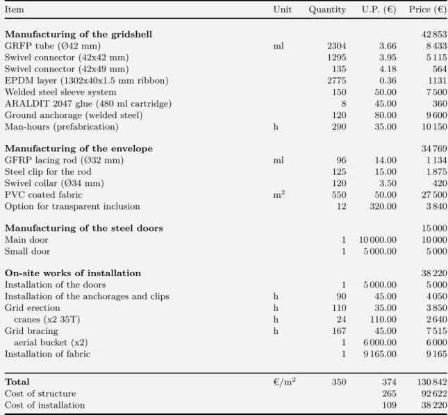
2.35 Cost allocation for the superstructure 113
■ ■ ■
3.1 Definition of the tangent vector and the osculating circle of a curve 131
a Curve's tangent 131
b Curve's normal and osculating circle 131
3.2 Osculating circles for a spiral curve at different parameters 135
3.3 Discontinuity of the Frenet trihedron at an inflexion point 137
3.4 Geometric interpretation of the angular velocity vector of a moving frame 141
LIST OF FIGURES
3.6 Angular velocities of Frenet and Bishop frames for a circular helix 150
a Frenet frame 150
b Bishop Frame 151
3.7 Discrete curve representation and parametrization 153
3.8 Several ways to define the osculating circle for discrete curves 157
a Vertex-based 157
b Edge-based 157
c Bitangent with‖ −1‖ 157
d Bitangent with‖ ‖ 157
3.9 Sensitivity of discrete curvatures to non uniform discretization 162
a Circumscribed (𝜑 = 𝜋/3) 162
b Circumscribed (𝜑 = 2𝜋/3) 162
c Inscribed (𝜑 = 𝜋/3) 162
d Inscribed (𝜑 = 2𝜋/3) 162
3.10 Sensitivity of discrete curvatures to non uniform discretization 163
3.11 Discretization of a semicircle and evaluation of its bending energy 166
3.12 Relative error in the estimation of the bending energy of a semicircle 167 a |1 −ℰ1
ℰ( )|in % 167
b |1 −ℰ3
ℰ( )|in % 167
3.13 Discretization of an elastica curve and evaluation of its bending energy 168
a Sequence of elastica curves 168
b Zoom on the discretization 168
3.14 Relative error in the estimation of the bending energy of an elastica 169 a |1 −ℰ1
ℰ( )|in % 169
b |1 −ℰ3
ℰ( )|in % 169
3.15 Definition of the tangent vector associated to the circumscribed curvature 171
a Current portion 171
b Start 171
c End 171
3.16 Definition of the tangent vector associated to the inscribed curvature 174
a Current portion 174
b Start 174
c End 174
3.17 Two methods to parallel transport a vector 178
LIST OF FIGURES
b Double reflection method 178
■ ■ ■
4.1 Curve-angle representation of the rod 192
a Bending strains 192
b Angular deviation 192
4.2 Succession of the degrees of freedom 195
4.3 Variation of the Bishop frame for a perturbation of the centerline 201
4.4 Measuring the variation of parallel transport : rotation of angle𝛼𝜖. 202
4.5 Measuring the variation of parallel transport : rotation of angle𝛹𝜖. 203
■ ■ ■
5.1 Description of the motion for a Cosserat rod : longitudinal section 224
5.2 Description of the motion for a Cosserat rod : transverse section 225
a Deformed cross-section𝒮( ) 225
b Deformed cross-section𝒮( + 𝑑 ) 225
c Reference cross-section𝒮( )
̄
225d Reference cross-section𝒮( + 𝑑 )
̄
2255.3 Equilibrium of an infinitesimal slice of rod 241
5.4 Typical deformation modes of cross-sections in Kirchhoff's theory 249
5.5 Geometric interpretation of Kirchhoff's equations 257
5.6 Geometric interpretation : influence of the curvature (𝜅) 258
a Infinitesimal deformation 258
b Contributions of the internal forces 258 c Contributions of the internal moments 258
5.7 Geometric interpretation : influence of the first material curvature (𝜅1) 260
a Infinitesimal deformation 260
b Contributions of the internal forces 260 c Contributions of the internal moments 260
5.8 Geometric interpretation : influence of the second material curvature (𝜅2) 264
a Infinitesimal deformation 264
LIST OF FIGURES
c Contributions of the internal moments 264
■ ■ ■
6.1 Centerline of the discrete biarc model 276
6.2 Calculation of the biarc parameters 283 a Geometric curvature at ghost vertices 283 b Unit tangent vector at ghost vertices 283 c Left/right unit tangent vector at handle vertices 283 d Unit tangent vector at handle vertices 283 e Left/right bending moment at handle vertices 283
6.3 Parabolic interpolation of the kinetic energy peak 299
6.4 Application of the DR process to the simple plane pendulum 306 a First steps until the first peak ofℰ is reached 306 b Potential energy of the pendulum for the first steps 306
6.5 Convergence of the DR process for the simple plane pendulum 307 a Typical profile of the kinetic damping 307 b Convergence of the DR process in the phase space 307
6.6 Partial class diagram of Marsupilami.Math.dll 313
6.7 Test case of a constrained arch 318
LIST OF TABLES
2.1 Key figures 66
2.2 Technical properties of the tube 82
2.3 Flexural tests of the GFRP tubes 84
2.4 Short-term and long-term values for material resistance 84
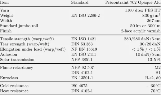
2.5 Technical properties of the membrane 100
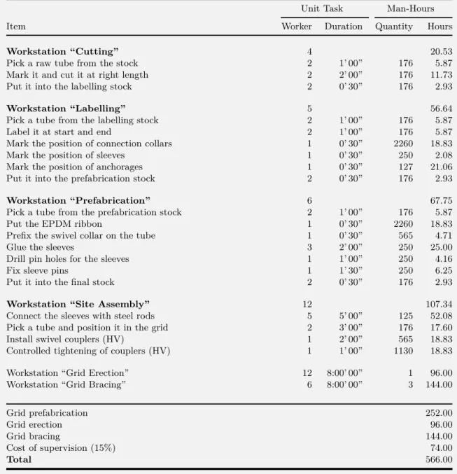
2.6 Man-hours spent by the volunteers on the fabrication 108
LIST OF TABLES
2.8 Cost details for the superstructure 112
■ ■ ■
3.1 Review of several discrete curvature definitions 158
■ ■ ■
5.1 Summary of the notations employed throughout this section 226
■ ■ ■
6.1 Number of segments, edges and vertices whether the centerline is closed or open 276
6.2 Simple cost model for arithmetic operations 316
6.3 Internal forces for the arch test case 320
6.4 Internal moments for the arch test case 321
6.5 Geometric parameters for the arch test case 322
■ ■ ■
A.1 Project review - general informations 338
INTRODUCTION
La paternité des structures de type gridshell élastique est couramment attribuée à l’archi-tecte et ingénieur allemand Frei Otto, qui les a intensivement étudiées au XXème siıcle.
Fruit de son travail de recherche, il réalise en 1975, en collaboration avec l’ingénieur Ed-mund Happold du bureau Arup, un projet expérimental de grande ampleur : la Multihalle de Mannheim [1, 2]. Cette réalisation emblématique ancrera durablement les gridshells dans le paysage des typologies structurelles candidates à l’avınement de géométries non-standard, caractérisées par l’absence d’orthogonalité. Cette capacité à former la forme de façon efficiente prend tout son sens dans le contexte actuel où, d’une part la forme s’impose comme une composante prédominante de l’architecture moderne (F. Gehry, Z. Hadid, Ĵ) et d’autre part l’enveloppe s’affirme comme le lieu névralgique de la performance des bâtiments, notamment environnementale.
Littéralement, le terme grid-shell désigne une résille à double courbure dont le comporte-ment mécanique s’apparente à celui d’une coque ; c’est à dire que les efforts y transitent principalement de maniıre membranaire. Ces ouvrages peuvent franchir de grandes
por-INTRODUCTION
tées en utilisant un minimum de matiıre. Cependant, il semble plus rigoureux et plus fidıle à l’histoire de désigner par gridshell élastique la combinaison indissociable d’un principe structurel ĸ le gridshell, une résille qui fonctionne telle une coque ĸ et d’une méthode constructive astucieuse ĸ la déformation réversible d’une grille de poutre initia-lement plane pour former une surface tridimensionnelle à double courbure. Le projet de Mannheim ĸ dans lequel une grille en bois de trame réguliıre, initialement plane et sans rigidité de cisaillement est déformée élastiquement jusqu’à la forme désirée via un dispo-sitif d’étaiement, puis contreventée pour mobiliser la raideur d’une coque et finalement couverte d’une toile ĸ pose les bases de ce nouveau concept et le rend populaire auprıs d’un large public d’architectes et d’ingénieurs de par le monde.
Cependant, en dépit du potentiel de cette typologie, trıs peu de projets ont vu le jour suite à la construction de la Multihalle. Il faut en effet attendre 25 ans et le développe-ment des méthodes de calcul numérique pour voir de nouveau éclore quelques réalisations iconiques : Shigeru Ban innove en passant du bois au carton pour la construction du Pa-villon de Hanovre en 2000 [3] ; puis viennent les gridshells en bois de Downland en 2002 [4] et de Savill en 2006 [5] qui reprennent fidılement les principes développés à Mannheim mais emploient des méthodes constructives différentes. Depuis une dizaine d’années le la-boratoire Navier a investi ce champ de recherche sous le double aspect de la structure et du matériau, donnant lieu à la réalisation de quelques prototypes (en 2006 et 2007 [6,7]) et des deux premiers bâtiments de type gridshell élastique en matériau composite construits à ce jour (Solidays 2011 [8] et Créteil 2013 [9]).1 Plus récemment, on a pu observer un certain engouement pour la construction de pavillons en bois de petite taille, non couverts, réalisés selon des principes similaires à ceux de la Multihalle, essentiellement dans le cadre de workshops pédagogiques ou bien de projets de recherche [10,11,12,13].
Il est naturel de se demander pourquoi cette innovation prometteuse peine ainsi à essai-mer ? S’il est vrai que la construction de la Multihalle de Mannheim a permis de prouver la faisabilité économique et technique du concept de gridshell élastique à grande échelle, il faut bien reconnaître que cette prouesse n’a été rendue possible qu’au terme d’un long pro-cessus de maturation pour développer et acquérir l’ensemble des compétences scientifiques, techniques, méthodologiques et humaines nécessaires à sa conception et à sa construction.2
1.Ici, le matériau employé, un composite à base de fibres de verre imprégnées dans une matrice polyester et obtenu par pultrusion, apporte un gain de performance très significatif par rapport au bois et permet de rester sur une conception à simple nape là où le bois aurait nécessité une grille à double nape beaucoup plus complexe à réaliser.
2.“This is not a case of a building creatively designed, but based on a support system of additive known elements. This design is the result of a symposium of creative thought in the formation, the invention of building elements with the
INTRODUCTION
En vérité, une telle dépense de moyens pour développer et rassembler ces compétences ne saurait assurer la reproductibilité de cette experience sauf en de trıs rares occasions et pour des projets d’exception. Par ailleurs, les techniques développées à l’époque sont pour partie tombées en désuétude (e.g. la recherche de forme par maquette physique) ou bien ont fortement évoluées voir mĝme mutées (e.g. le calcul numérique). Des matériaux nouveaux, composites, ont vu le jour. Ils repoussent les limitations intrinsıques des matériaux usuels tel que le bois et offrent des performances techniques bien plus intéressantes pour ce type d’application (durabilité, allongement à la rupture, légıreté, résistance mécanique, fiabilité de niveau industrielle, Ĵ). Enfin, notons que le cadre réglementaire s’est considérablement étoffé apportant aussi son lot de rigidités vis-à-vis de la pénétration des innovations dans le secteur de la construction.
Ainsi la conception des gridshells se pose-t-elle en des termes nouveaux aux architectes et ingénieurs actuels. Elle se heurte aux deux difficultés majeures suivantes :
■ La premiıre difficulté est d’ordre technique et concerne la fonctionnalisation de la
struc-ture. En effet, bien que le principe du gridshell permette de réaliser des ossatures courbes de maniıre optimisée, il n’en reste pas moins complexe de constituer à partir de cette résille porteuse une véritable enveloppe de bâtiment capable de répondre à un large panel de cri-tıres performantiels (tels que l’étanchéité, l’isolation thermique, l’isolation acoustique, Ĵ) sur un support qui ne présente aucune rationalité géométrique.3
■ La seconde difficulté est d’ordre théorique et concerne la mise au point d’outils et de
processus de conception adaptés à l’étude de ces structures d’un genre nouveau où Archi-tecture et Ingénierie collaborent de maniıre indissociable à l’identité formelle de l’ouvrage. L’inadéquation des méthodes et des outils de design actuels, orientés davantage vers la justification des ouvrages que vers leur conception, constitue un des principaux freins à la diffusion de cette innovation.
Le présent manuscrit s’articule autour de deux grandes parties qui tentent chacune de construire des éléments de réponse aux défis identifiés précédemment. La premiıre partie, composée des chapitres 1 et 2, est destinée à présenter en profondeur le concept de gridshell
simultaneous integration of the theoretical, scientific contributions from mathematics, geodesy, model measuring, statics as well as control loading and calculation. We are dealing with more than pure ‘teamwork’, we are dealing with team creation.” [Georg Lewenton1, p. 201]
3.Pour contourner cette difficulté, une approche prometteuse consiste à identifier des classes de surfaces courbes (comme les maillages isoradiaux) dont certaines propriétés géométriques (e.g. facettes planes, noeuds sans torsion) s'avèrent avan-tageuses sur le plan constructif [14].
INTRODUCTION
élastique, son potentiel et les difficultés techniques sous-jacentes (voirpartie I). La seconde partie, composée des chapitres 3 à 6, est consacrée au développement d’un élément de poutre discret original prenant en compte les sollicitations de flexion et de torsion et applicable à tout type de section dont le centre de torsion est confondu avec le centre de masse, ainsi que certains types de discontinuités liées à la présence de connexions dans les résilles de type gridshell (voirpartie II). Cette seconde partie constitue le coeur académique de ce travail de thıse.
Dans le chapitre 1 nous rappelons la genıse de cette invention et nous en donnons une définition précise et actualisée. Puis nous dressons un état des lieux critique des projets réalisés sur ce principe depuis le début des années 1960 à nos jours. Cette brıve histoire des gridshells dessine à elle seule le potentiel de ces structures, notamment en terme d’expression formelle et de performance structurelle. Loin de les enfermer dans un style d’architecture particulier, elle en souligne au contraire la formidable variété. Cette revue de projet est complétée par une revue approfondie de la littérature existante sur l’ensemble des domaines connexes à cette thématique (géométrie, structure, matériaux, logiciel). Dans lechapitre 2nous présentons de maniıre détaillée la conception et la réalisation de la cathédrale éphémıre de Créteil, un gridshell élastique en matériau composite construit en 2013 et toujours en service. Cette expérience peu commune a été une source inépuisable pour alimenter ce travail de thıse. Cette relecture expose les méthodes et les outils de conceptions développés pour faire aboutir le projet, les difficultés rencontrées, les pistes d’amélioration. Elle fournit également une analyse économique pour cerner les axes de progrıs prioritaires dans l’optique d’une commercialisation future.
Dans lechapitre 3 nous rappelons les notions fondamentales déjà connues, indispensables à notre étude, pour la caractérisation géométrique de courbes de l’espace et de repıres mobiles attachés à des courbes. Ces notions sont présentées pour le cas continu puis pour le cas discret ; ce dernier étant essentiel pour la résolution numérique de notre modıle. Cependant, nous observons que la notion clef de courbure géométrique perd son univocité dans le cas discret. Nous identifions alors plusieurs définitions de la courbure discrıte. Puis nous les comparons selon des critıres propres à notre application (convergence géo-métrique, représentativité énergétique, forme d’interpolation). A l’issu de cette analyse, la définition la plus pertinente est retenue pour le développement du nouveau modıle numérique au cours des chapitres suivants.
Dans lechapitre 4nous élaborons un premier modıle de poutre à 4 -DOFs par une approche variationnelle. Ici nous reprenons et enrichissons un travail initié lors d’une précédente thıse [15] inspirée par des travaux récents sur la simulation des tiges élastiques dans le
INTRODUCTION
domaine des computer graphics [16], et à laquelle j’ai collaboré [17,18]. En particulier, notre développement permet d’aboutir à des expressions purement locales des efforts internes et prouve l’équivalence avec le membre statique des équations de Kirchhoff. Sur le plan mathématique, le modıle est développé en continu et son implémentation numérique n’est pas traité.
Dans lechapitre 5nous développons une nouvelle approche, plus directe et plus complıte, pour construire à partir des équations de Kirchhoff un élément de poutre enrichi par un noeud fantôme et possédant lui aussi un nombre de degré de liberté minimal. L’originalité de cet élément est de pouvoir localiser proprement dans l’espace certains types de discon-tinuités, notamment des discontinuités de courbures provoquées par des efforts ponctuels ou des sauts de propriétés matérielles. Cela permet une modélisation plus fine des phéno-mınes physiques au sein de la grille, aussi bien au niveau des connexions que des conditions aux appuis, ce qui était le principal objectif de ce travail de thıse.
Dans lechapitre 6 nous combinons les résultats des chapitres précédents pour construire un élément de poutre discret tout à fait adapté à la modélisation numérique des gridshells élastiques. Nous présentons la construction de cet élément et la méthode de résolution nu-mérique employée pour trouver l’état d’équilibre statique du systıme, à savoir le relaxation dynamique. Enfin, nous donnons quelques éléments sur Marsupilami, le programme infor-matique que nous avons mis au point et qui implémente l’élément de poutre discret élaboré au cours de cette thıse. Nous exposons aussi quelques résultats de comparaison avec des logiciels du commerce qui ont permi de valider notre travail. Plus généralement, l’élément développé convient bien pour modéliser des problımes de couplage flexion-torsion dans des poutres élancées, comme par exemple les phénomınes de repositionnement des câbles et des gaînes accrochées aux bras robots, un matériel industriel qui se démocratise à grande vitesse.
ELASTIC
GRIDSHELL
Chapter 1
ELASTIC GRIDSHELLS
1.1
INTRODUCTION
This chapter is meant to define and introduce what elastic gridshell structures are. It develops a comprehensive but precise view of the numerous knowledge and know-how that gravitate around this concept.
1.1.1 OVERVIEW
We naturally begin this chapter by defining the notion of elastic gridshell and the context in which this technology arose (see §1.2). We briefly highlight the benefits of composite materials for this kind of structure. We then propose two thorough reviews : the first one is dedicated to known built elastic gridshell structures (see §1.3) while the second one is a literature review of the main works related to the topic of elastic gridshells (see§1.4).
ELASTIC GRIDSHELLS
1.1.2 CONTRIBUTIONS
■ We establish a chronological review of known built elastic gridshells, from the very
be-ginning of this technology to the present time. We reveal the richness of this concept by exhibiting the great variety of realised projects. We discuss the specificities brought by each one of these projects.
■ We establish an up-to-date review of the existing scientific literature, crossing multiple
fields of research (geometry, mechanics, material, Ĵ).
1.2
DEFINITION
The invention of the elastic gridshell concept is commonly attributed to Frei Otto, a German architect who devoted several years to gridshells. In 1975 he achieved the famous
Mannheim Multihalle [2], a wooden shell of 7500 m2, in collaboration with the engineer
Edmund Happold (Arup). Literally, the word “gridshell” refers to grids behaving like shells : from a mechanical point of view that means stresses acting on the structure are mainly transmitted through compression and tension. These structures can cross large-span with very little material.
However, according to the historic evolution of the concept, to characterise a gridshell as the combination of a structural concept (a grid behaving like a shell, see §1.2.2) and a specific construction process (see§1.2.1) using the bending flexibility of the material (see
§1.2.3) seems to be more accurate. The project of Mannheim ĸ in which a wooden regular
and planar grid, lacking shear stiffness, is elastically deformed up to a targeted shape with the help of stays, and then braced and covered ĸ is regarded as the starting point of this new concept (seefigs. 1.1ato1.1d).
This type of gridshell, known as elastic gridshell, offers a very elegant manner to materialise freeform shapes from an initially flat and regular grid, which obviously has many practical benefits : planar initial geometry, standard connection nodes, standard profiles and so on. Note that the term rigid gridshell is often opposed to the term elastic gridshell to indicate reticulated structures that behave like shells but are not formed in an active-bending process.
1.2.1 ERECTION PROCESS
Usually, the grid morphology is not trivial and leads to design numerous costly and complex joints. To overcome this issue, an original and innovative erection process was developed
1.1Forming process of the gridshell of Mannheim, Ger-many
1.1aAssembly of the timber grid
1.1a 1.1bDeformation of the grid1.1b
1.1cFinal shape of the lattice
1.1c
1.1dRoofing with a membrane
1.1d
1.1 Forming process of the gridshell of Mannheim, Germany
1.1a Assembly of the timber grid
1.1b Deformation of the grid
1.1c Final shape of the lattice
ELASTIC GRIDSHELLS
that takes advantage of the flexibility inherent to slender elements. A regular planar grid made of long continuous linear members is built on the ground (seefig. 1.1a). The elements are pinned together so the grid has no in-plane shear stiffness and can accommodate large-scale deformations during erection. Then, the grid is bent elastically to its final shape (see
figs. 1.1b and 1.1c). Finally, the grid is frozen in the desired shape with a third layer
of bracing members and the structure becomes a shell. This process is illustrated and detailed in the next chapter (see§2.3).
1.2.2 STRUCTURAL TYPOLOGY
Their mechanical behaviour is very similar to the one of real shells even if the material is discrete and located in a grid more or less open. Moreover, gridshells benefit from the same advantages as the ones showed by an eggshell : they can cross large span using a low amount of material. Their stiffness is mainly linked to their double-curved shape.
1.2.3 MATERIAL FLEXIBILITY FOR STRUCTURAL RIGIDITY
In this field of application, composite materials like glass fibre reinforced polymer (GFRP) could favourably replace wood, where both resistance and bending ability of the material is sought [7]. The stiffness of the structure does not derive from the intrinsic material rigidity but principally from its geometric curvature. Ideally, the composite profiles are produced by pultrusion, an economic continuous moulded process. The standardisation of the process guaranties very stable material and mechanical properties. It frees designers from the painful problematic of wood joining and wood durability. The characterisation of this material is presented further in the thesis (see§2.5).
1.3
BUILT ELASTIC GRIDSHELLS : A REVIEW
No thorough historic review is available about executed projects of elastic gridshells al-though some partial reviews have been done time to time on the occasion of scientific works or construction projects. This review aims at filling this gap by giving an overview of the development of the concept from the very beginning to the very last experiments. Only known built projects have been identified and reported here. The only condition for a project to belong to this review is to comply with the definition of what an elastic grid-shell is (see §1.2), independently to any other consideration (material, fabrication, size, cladding, Ĵ).
1960 1970 1980 1990 2000 2010 2020 5 10 20 40 80 Mannheim Hannover Downland Savill Créteil Year Spa n (m)
Metal Timber Composite
1.2Known elastic gridshells built by the past
1.2 Known elastic gridshells built by the past
The surface of the bubbles is proportional to the covered area. Colour indicates the material employed for the rods.
ELASTIC GRIDSHELLS
The informations collected during this research work are given in table format in appendix
(seechapter A). A synthetic presentation of these datas is proposed to the reader infig. 1.2,
where projects are ordered by date, span, covered area and material.
The books edited by the Institut für leichte Flächentragwerke are of great interest to under-stand the beginnings. IL10 Grid Shells [19] has a precise inventory of the first experiments from 1962 to 1976, while IL13 Multihalle Mannheim [1] focuses on the construction of the Multihalle in Mannheim. Timber gridshells: architecture, structure and craft [20] is a significant effort but focuses exclusively on medium to large scale projects in timber. A small but general partial review is also available in [21]. An interesting review is also given by Quinn and Gengnagel [22] as part of their research work on new erection methods. A review of bracing and cladding systems is done in [23]. A review of form-finding methods is done in [24]. Finally, various valuable reviews are available in the thesis of Douthe [25], Bouhaya [26], Tayeb [27], and Lafuente Hernández [28].
1.3.1 THE BEGINNINGS : FROM THE FIRST PROTOTYPE TO THE GERMAN PAVILION
Frei Otto started his studies in architecture in 1947 in Berlin, Germany, and completed his doctorate on tensile structures in 1953. This first work was published and translated later in the 60’s. He then began to work in the field of lightweight structures using physical models such as soap films or hanging nets, and photographic measurements.1,2 These tools were essentials for his exploration of forms and structures as there were no computers at that time.
Steel Gridshell, Berkeley, USA, 1962
Simultaneously, he became interested by the study of lightweight shells and the way they were form-found. One of his very first elastic gridshell was built in 1962 with students at Berkeley, USA [19, p. 270]. It is funny to remark that this first gridshell was not a timber gridshell but a steel gridshell made out of twin steel rods linked in a grid fashion by bolts with clamping plates (seefig. 1.3a). This first experiment demonstrated at small scale the
1.In the 19thand 20thcenturies model testing was at the heart of structural innovation [29]. Analog models were employed
successfully by well-known architects and engineers to go beyond the limits of existing knowledge (A. Gaudi, H. Isler, F. Candela, F. Otto, …) and are still employed today where numeric models failed to represent accurately some physical phenomenons (for instance in wind analysis for high rise towers and bridges).
2.“Photography is the medium through which the form and content of a model are communicated. It is one of our most important tools in that it provides the basis for documentation and information, supplements our creative potential […] ” [19, p. 56]
1.3Steel gridshell built in 1962 in Berkeley, USA 1.3aSteel lattice 1.3a 1.3bKnot detail 1.3b
1.4Timber gridshell built in 1962 in Essen, Germany
1.5Timber gridshell built in 1967 in Montreal, Canada
1.5
1.3 Steel gridshell built in 1962 in Berkeley, USA
1.3a Steel lattice
1.3b Knot detail
1.4 Timber gridshell built in 1962 in Essen, Germany
BUILT ELASTIC GRIDSHELLS : A REVIEW
ability to bend a regular grid with no shear rigidity into a curved shape (see fig. 1.3b). The grid was loosely braced and shell effects were not investigated.
Essen Gridshell, Essen, Germany, 1962
The same year he designed and built a first timber gridshell in Essen, Germany [19, p. 272]. The prototype ĸ a single-layer gridshell spanning 17 m and covering an area of 198 m2 ĸ
was made with 3-plies laminated timber profiles in hemlock pine (seefig. 1.4). The cross-section of the profiles was rectangular (60 mm x 40 mm) and the elements were assembled in a grid fashion with simple steel bolts. Once erected, nothing was specifically done to improve the in-plane shear stiffness of the grid and activate a shell behaviour. Finally, the structure was covered with a transparent plastic foil nailed directly on the grid’s profiles. German Pavilion Auditoria, Montreal, Canada, 1967
Five years later, on the occasion of the 1967 International and Universal Exposition in Montreal, Canada, Frei Otto was appointed to design the German Pavilion : a large cable net tent prefiguring the realisation of the olympic stadium of Munich, Germany, in 1972.3,4 The pavilion required two auditoria and these were designed using the principle of elastic gridshell [19, p. 274]. All together, the auditoria covered and area of 365 m2and spanned
17.5 m. The construction technique employed in Montreal was quite similar to the one developed in Essen, but this time the grid was fully braced with a layer of nailed plywood boards and offered a proper roofing made out of insulation panels covered with a PVC coated fabric (seefig. 1.5).
The two gridshells built in Montreal mark a significant step in the maturation process of the technique leading to the major realisation of Mannheim in 1976 : a methodology has emerged to progress “from the inverted form to the gridshell” [19, p. 179] ; main construction details have been validated ; various erection methods have been tested ; mid-scale buildings have been built to host public. However, due to the over complexity of these structures, lots of unknowns remained unsolved at this stage and the behaviour of the structures could not be fully predicted.5
3.Actually, Frei Otto became the director of the newly founded Institute for Lightweight Structures (Institut für Leichte Flächentragwerke or IL) at the University of Stuttgart in 1964. It was the IL that was commissioned by the German government to conduct research in connection with the planning of the German pavilion for the exposition in Montreal.
4.Video of the construction of the German pavilion :https://www.youtube.com/watch?v=Z0mtFMoseUk.
5.“Snow accumulations in the throat of the common edge beam probably caused one of the two grid shells of project Montreal to buckle in a relatively flat region. The diameter of the buckled area was about 3 meters. Neither grid rod was
ELASTIC GRIDSHELLS
It is worthwhile to mention that several unexecuted large-scale projects were studied by Frei Otto between 1967 and 1973 at the IL or at the Atelier Warmbronn.6 These projects are basically documented in [19, pp. 278 - 288] and reveal that he was training his capacity to master large-scale projects with the technique of elastic gridshells for more conventional building projects (wave pool, swimming hall, multi-purpose hall, auditorium, Ĵ).
1.3.2 MANNHEIM MULTIHALLE : THE COMPLETION OF A DECADE OF RESEARCH
The project of the Multihalle started in 1970, when the decision was made that Mannheim, Germany, would hold the Bundesgartenschau in 1975.7 The architects of the project, Carl Mutschler & Partners, consulted Frei Otto at Atelier Warmbronn as he was starting to
get known in the filed of innovative lightweight structures. This is how the idea of the gridshell was introduced in the project [30].
A thorough report on the project is available in [1]. A more condensed but still precise description of the engineering problematics related to this project are available in the excellent papers from Happold and Liddell [2] and Liddell [30].
Multihalle, Mannheim, Germany, 1975
Mannheim is an unprecedented realisation because it is more than twenty times larger than the previously built gridshells in Montreal and is meant to last many years and not only for the duration of a short-term exhibition. The timber lattice, still existing in 2017, covers an area of 7400 m2 (seefig. 1.6a). It is composed of two interconnected domes, one
for the multi-purpose hall (span : 60 m | height : 20 m) and one for the restaurant (span : 50 m | height : 18 m).
Although the constructive system deployed in Mannheim clearly inherited from the pre-vious developments, the challenge was such that it had to be revisited. In particular the main additions were the introduction of the double-layer system and the proper bracing of the grid. A major advance was also the use of the very first numeric models to study the structure.
The double-layer system was introduced to tackle two issues : the grid needed some flexibility to be bent into the desired shape, but once erected it should provide sufficient
broken, i.e. the buckling progressed elastically. It might have been possible to press the buckled area back into shape.” [19, p. 219]
6.Atelier Warmbronn is the architectural studio founded by Frei Otto in 1969.
1.6Timber gridshell built in 1975 in Mannheim, Germany 1.6aSky view
1.6a
BUILT ELASTIC GRIDSHELLS : A REVIEW
bending stiffness to resist disturbing loads and avoid a buckling collapse.8 Once erected, the two grids, one sliding on top of the other one, were connected together to form a single grid with much higher ladder profiles (from 50 mm to 150 mm), increasing their bending stiffness by a factor of about 26 (seefig. 1.6b).
Because the in-plane stiffness of the grid also plays a major role in the resistance to buckling, this question was considered with care. The bracing of the grid was first achieved by preventing the nodes to turn once the grid was erected. This was done by creating some friction in the nodes when tightening the bolts linking the laths, after the grid was erected. Then, additional bracing cables were put in the grid.
8.Theoretically, self-weight loads would produce only compression in the members because the (funicular) form of the grid resulted from the inversion of a hanging chain model in pure tension.
1.6bInterior view
1.6 Timber gridshell built in 1975 in Mannheim, Germany
1.6a Sky view
ELASTIC GRIDSHELLS
Finally, the project of Mannheim was a key project in the development of modern lightweight structures. Great engineers were born in touch with Frei Otto, following his footsteps or collaborating with him. This heritage has irrigated for several decades the engineering of lightweight structures in Europe and gave birth, directly or indirectly, to several studios among which we can cite Buro Happold and Schlaich Bergermann & Partner.
1.3.3 THE DRY PERIOD : 25 YEARS FROM MANNHEIM TO HANNOVER
Although the experience of Mannheim proved the feasibility and the potential of gridshell structures for large-scale projects, it also revealed that these projects were subject to an incredible complexity in terms of structural design, geometry, modelling, testing, team work, construction methods Ĵ At that time, very few people could pretend to master all the knowledge and techniques required to design and built timber gridshells and developed in the bosom of the Institute for Lightweight Structures in Stuttgart.
This project was obviously well ahead of its time and the engineering cost to design such structures was probably prohibitive considering the tools available at that time. This certainly explains why no elastic gridshells were built during the 25 following years, despite the optimism of the pioneers of the Multihalle.9
Note that around 1975 small workshop and experiments lead to the construction of several but small elastic gridshells, as reported in [19]. A non-exhaustive but quite extensive list of known executed gridshell projects is presented in fig. 1.2. The dry period is clearly visible.
1.3.4 THE SIGNS OF A RENEWAL : DORSET AND DONCASTER
It is only 20 years later that gridshells started to reappear, in the late 90’s mainly in the United Kindom, and for projects that had interest in environmental problematics. Westminster Lodge, Dorset, England, 1995
In 1995, a small student residence named Westminster Lodge was built in Dorset, England. This dwelling was part of a larger project ĸ Hooke Park ĸ aiming at investigating how the local forest resources, in particular immature roundwood thinnings, could be better
9.“For many years after its completion, Happold promoted the benefit of the timber gridshell as a construction technique and stated that he could not understand why it had not been adopted more widely. He perceived the benefits to be in the efficiency of the construction method to enable doubly curved (shell) structures to be constructed quickly and cost effectively.” [31].
1.7Roundwood gridshell built in 1995 in Dorset, England 1.7aInterior view
1.7a 1.7bExterior view1.7b
1.8Timber gridshells built in 1998 in Doncaster, England 1.8aInterior view
1.8a
1.8bExterior view
1.8b
1.7 Roundwood gridshell built in 1995 in Dorset, England
1.7a Interior view
1.7b Exterior view
1.8 Timber gridshells built in 1998 in Doncaster, England
1.8a Interior view
![fig. 1.16a ) and in 2007 (see fig. 1.16b ) [ 6 ]. These structures were left outside for about 7](https://thumb-eu.123doks.com/thumbv2/123doknet/2918726.76286/74.864.77.716.94.345/fig-a-fig-b-structures-left-outside.webp)