HAL Id: hal-01204649
https://hal.archives-ouvertes.fr/hal-01204649
Submitted on 20 Jun 2017HAL is a multi-disciplinary open access archive for the deposit and dissemination of sci-entific research documents, whether they are pub-lished or not. The documents may come from teaching and research institutions in France or abroad, or from public or private research centers.
L’archive ouverte pluridisciplinaire HAL, est destinée au dépôt et à la diffusion de documents scientifiques de niveau recherche, publiés ou non, émanant des établissements d’enseignement et de recherche français ou étrangers, des laboratoires publics ou privés.
METHODOLOGY OF REVERSE ENGINEERING
FOR LARGE ASSEMBLIES PRODUCTS FROM
HETEROGENEOUS DATA
Marina Bruneau, Alexandre Durupt, Lionel Roucoules, Jean-Philippe Pernot,
Harvey Rowson
To cite this version:
Marina Bruneau, Alexandre Durupt, Lionel Roucoules, Jean-Philippe Pernot, Harvey Rowson. METHODOLOGY OF REVERSE ENGINEERING FOR LARGE ASSEMBLIES PRODUCTS FROM HETEROGENEOUS DATA. TMCE 2014, May 2014, Budapest, Hungary. pp.10. �hal-01204649�
Science Arts & Métiers (SAM)
is an open access repository that collects the work of Arts et Métiers ParisTech researchers and makes it freely available over the web where possible.
This is an author-deposited version published in: http://sam.ensam.eu
Handle ID: .http://hdl.handle.net/10985/10156
To cite this version :
Marina BRUNEAU, Alexandre DURUPT, Lionel ROUCOULES, Jean-Philippe PERNOT, Harvey ROWSON - METHODOLOGY OF REVERSE ENGINEERING FOR LARGE ASSEMBLIES PRODUCTS FROM HETEROGENEOUS DATA - In: TMCE 2014, Hongrie, 2014-05-19 - TMCE conference - 2014
Proceedings of TMCE 2014, May 19-23, 2014, Budapest, Hungary, Edited by I. Horváth, Z. Rusák
Organizing Committee of TMCE 2014, ISBN 978-94-6186-177-1
1
A METHODOLOGY OF REVERSE ENGINEERING FOR LARGE ASSEMBLIES
PRODUCTS FROM HETEROGENEOUS DATA
Marina Bruneau
Roberval Laboratory
University of Technology, Compiègne [email protected]
Alexandre Durupt
Roberval Laboratory
University of Technology, Compiègne [email protected]
Lionel Roucoules Jean-Philippe Pernot
Arts et Métiers Paris Tech, Aix-en-Provence CNRS, LSIS
[email protected] [email protected]
Harvey Rowson
DeltaCAD S.A. Lacroix Saint-Ouen, France
ABSTRACT
Reverse-Engineering techniques are commonly used to generate or update the CAD model of a single physical object. However, the reverse engineering of a whole assembly is still very tedious and time-consuming. This is mainly due to the fact that the complete definition of the final digital mock-up relies on the integration of multiple sources of heterogeneous data, such as point clouds, images, schemes or any type of digital representations which are not yet fully supported by actual software. This paper proposes a new method and tool to better integrate those multi-representations and to speed up the reconstruction process which could therefore become adapted to the reconstruction of large mechanical assemblies such as in automotive field. The conceptual model of the methodology suggested enables to extract geometrical mark from the heterogeneous data thanks to segmentation and to identify mechanical components. In our approach, “signature” plays a key role in the identification and it is considered as a set of characteristics to describe an object. This article presents a demonstrator to illustrate this methodology using an example from automotive domain.
KEYWORDS
System engineering methodologies, Managing
product/process knowledge, Capturing product
information, Reverse Engineering, Signature
comparison.
1. INTRODUCTION
Reverse Engineering is an activity which consists in, defined by Varady et al. [30] about twenty years ago, “the transformation of real parts into engineering models and concepts while conventional engineering transforms engineering concepts and models into real parts”. In industry, many reasons of using this activity can be cited:
(1) The original design is not supported by sufficient or existing technical documents (it concerns old parts; all traceability of design is lost). It means that digital data such as CAD models, drawings and technical documents have been lost or to re-design an existing part. The aim could be to perform new simulations before modifying and remanufacturing the part ; (2) the original supplier disappeared or does not manufacture the part anymore and the original part is damaged or broken and no plan nor drawing are available. RE activity is also used to inspect the
manufactured product in line production with the DMU (Digital Mock-UP). The aim is to prevent all dimensioning derivations (the nautical industry is mainly concerned). To finish, RE activity is also applied to update the DMU of the product along its lifecycle (the aeronautic context is concerned in order to preserve the DMU of an airplane during its lifecycle).
To sum up, in the manufacturing industry, there is a large scope of applications from the re-design or maintenance of mechanical products to knowledge capitalization. Until now, RE has been used for single parts but the needs have evaluated: the new trend is to apply this technique to large mechanical assemblies which is a very tedious task. This paper highlights a mean to reverse large mechanical assemblies like in the automotive or naval construction fields where digital mock-ups can reach several hundreds of components. Depending on whether an initial digital mock-up exists or not, three use-cases are suggested and considered in order to generate and/or update the final digital mock-up: (1) as design-as built; (2) as design-as maintained; (3) from scratch. Considering these facts, a French project called “METIS” (3D modelling of Digital Mock-up based on the integration of heterogeneous data) has been launched in 2012. METIS proposes a methodology to retrieve a parameterized digital mock-up using a set of heterogeneous data such as drawings, pictures, maintenance documents and CAD models. METIS system will be composed of a database of signature of components. “Signature” is considered as a set of characteristics allowing to describing an object. The object could be represented in several sources of data. There is thus dedicated signatures to each heterogeneous data. METIS is also composed of a part dedicated to the classification and segmentation of heterogeneous data (picture, points cloud, CAD model…) and then the identification of components and then assemblies (resulting of segmentation) inside each data. This step relies on signatures mechanism of the component and which
enables to retrieve geometrical mark in
heterogeneous data.
This paper mainly addresses the way to extract
geometrical entities1 from the heterogeneous data
thanks to segmentation and to identify signature
1 Geometrical entities: literally, defined as a set of
geometrical data allowing to locate a spatial entity or to describe the shape.
processes. The contribution allows suggesting generic signature instantiated in the database. Then, the identification of the mechanical parts and assemblies according to the type of data could be performed.
This paper is organized as follows: section 2 presents the related works in link with the RE of large assemblies and the signature and segmentation mechanisms depending of the type of data processed. A general methodology will be presented and the definition of the conceptual elements enabling to link digital mock-up and heterogeneous data relying on data characterization are presented in section 3. Then the conceptual model will be illustrated thanks to the demonstrator developed for “METIS” project in section 4. To finish, a discussion of the approach is presented in this paper and some perspectives are suggested.
2. RELATED WORKS
This section is structured in four subsections: the two first present the related works in link with the Reverse Engineering of mechanical component and assemblies. The third one deals segmentation of heterogeneous data (points cloud, picture, CAD etc.). The last part concerns the signatures and their mechanism.
2.1. Reverse Engineering for
mechanical assemblies
Herlem et al. [13] use points clouds to propose a methodology in order to compare Digital Mock-Up (DMU) maturity. Thanks to Reeb graph method, he compares the real product with the initial DMU and updates it in order to increase product lifecycle
efficiency. The VPERI [31] (Virtual Parts
Engineering Research Initiative) project was created by the US Army Research Office in order to provide the vision, strategy, and methodology to help solve problems of long lifecycle product maintenance. A design interface is used to allow the addition of knowledge in the form of algebraic equations that represent engineering knowledge such as the functional behaviour of the components, the physical laws that govern the behaviour, the spatial
arrangement, etc. This interface provides
mechanisms that guide designers to ascertain that the functional requirements are fulfilled and helps designers to explore alternatives by assisting them as they make changes. In RE, SATTIC [3] proposed to categorize shapes issued from the analysis of videos
3 Marina Bruneau, Alexandre Durupt, Lionel Roucoules, Jean-Philippe Pernot, Harvey Rowson and photos. In the same field, IMASEG3D [15]
project proposes a solution for identification and segmentation of pictures taken thanks to a digital camera. Then, in order to integrate multi-model data and research similar model in a data-base, the project EROS3D [2] has been developed in the domain of art objects.
Thus, all these works focus on RE on single data but cannot be applied to a whole assembly without human intervention and the notion of “mechanical assembly” is not addressed yet.
2.2. Reverse Engineering for mechanical components
Several software solutions propose semi-automatic
solutions for Reverse Engineering such as
RapidForm®, Geomagic Spark® and Quick Shape
Reconstruction tool in Catia V5®. They enable to extract sketches and design parameters in order to recreate CAD model. They start from points clouds generating bordering curves by automatic freeform recognition. Once the canonic shapes are recognized (plane, sphere, cylinder, cone), final shapes are filled out depending of the conditions of tangency and curvature in order to get back a CAD model which can be edited; given then a frozen model. The final
model in RapidForm® and Quick Shape
Reconstruction can be edited for design parameterization; however the features detected during the segmentation step are not necessarily corresponding to the knowledge expertise used in the context given. Indeed the detected features are not parameterized according to the expertise of the RE engineer. A next design step in classical CAD modeler is necessary to obtain a parameterized CAD model according to expertise of Reverse Engineer.
Geomagic Spark® proposes to reverse mechanical
assemblies but the final digital mock-up is composed of frozen solid and the model cannot be parameterized for redesign.
The related works are mainly dedicated to feature recognition techniques and consist in extracting a geometry which represents design intent. Feature recognition can be generally defined as the ability to automatically or interactively identify and group topological entities from a solid model into functionally significant features such as faces, cylindrical holes, slots, pockets and fillets (i.e. extracting features and their parameters from solids models). Most common feature recognition methods consist in searching the boundary of a solid
according to a pattern of faces and edges that obey given topology of geometrical relationships. Features recognition is very advantageous because it allows
solid modeling, which improves quality of
reconstruction CAD model and it opens redesign possibilities. For example, one of the most famous applications is REFAB (Reverse Engineering Feature Based) in which Thompson et al. [28] presented a
classical geometric features-based reverse
engineering system. The developed prototype creates interactively the CAD model of a part with a significant number of specialized manufacturing features such as holes, pockets and so on. This tool enables the user to fit features such as cylinder and planes into points cloud. The segmentation, the fitting and the constraints are performed from the points cloud and the features are used as references. Only five manufacturing features are performed and 2.5D (axis milling possible in milling machine context) is considered.
In the same way, Sunil and Pande [26] extract sheet metal feature in a points cloud. Urbanic et al. [29] extract turning features. The library of features suggested in related works above focuses on specific manufacturing processes and it is a list of specific scripts of feature recognition and generation in a points cloud.
More recently works such as Su et al. [25] use “a fully statistical model where the data is modeled using a Poisson process on the object’s boundary (curves or surfaces)”. After estimation of individuals shapes in 2D, the process enables to retrieve a common shape from a 3D shape database. Mehdi-Souzani et al. [19] propose a methodology “to compute the distance between the real object shape and an existent CAD-model for conformity checking” within the context of RE. Falcidieno and Giannini [11] give a methodology for automatic recognition of shape-based features divided in three steps: feature recognition, feature extraction and feature organization.
Bénière, et al. [4] propose an automatic and quick retro-engineering process “to reconstruct a B-Rep model composed of planes, spheres, cylinders and cones from a 3D mesh whose vertex coordinates are considered exact”. The proposed method is divided
into three steps: primitive extraction; wire
reconstruction and B-Rep creation.
All these solutions use only points cloud data in order to “reverse” mechanical assemblies.
In the next section, the results that can be retrieved from segmentation techniques according of each type of data are presented in order to reverse from a set of heterogeneous data. The next subsection highlights the segmentation technics.
2.3. Segmentation techniques
Many works concerning segmentation data are existing and the aim of this section is to present the most relevant works concerning 3D models (points cloud and CAD data) and 2D elements (pictures) to finish with non-dimension document (text file, PDF). For points cloud and meshed data:
The segmentation of a meshed 3D points cloud is a research field which consists in the division of the 3D points cloud of a given object into a set of n points clouds representing the n features that compose this object. Three segmentation techniques are commonly used. In a first place, region based technique uses spatial coherence of the data to organize the mesh into meaningful groups. The best techniques are based on the approximation by bi-polynomial surfaces [14] and allow the recognition about simple shapes such as plan, cylinder, spherical and conical surfaces. In second place, a technique used is the edge-based method, consists in intending to isolate discontinuities in the 3D points cloud. Break areas such as steps and discontinuities of normal and curvature orientation are recognized. Points’ detection through parallel slicing sections is the simplest method. Sections are approximated by B-Splines [23]. A second technique consists in performing local characteristics [23]. In a third place, hybrid technique, which combines region and edge techniques, is used. For example, Yokoya and Alrashdan [32] [1] have performed the calculation of the discontinuities in the cloud. Region techniques are used in order to finalize the segmentation. The CAD is only on a geometric view and is generally frozen.
For pictures data:
Objects can be identified thanks to edge detection. A large scope of algorithms such as Canny [8] and Sobel, Roberts etc. have been compared by Bin and Samiei [6], Heath et al; [12] and Zhou et al. [33]. Hough transform has been used to detect lines and curves in the works of Duda and Hart [10]. Then Shrivakshan and Chandrasekar [24] suggest a methodology combining edge detection and shape matching using object morphological features in
order to detect an object inside an image. SCERPO
vision system (an acronym for Spatial
Correspondence, Evidential Reasoning, and
Perceptual Organization) [18] is an efficient method to recognize an object whatever its orientation by grouping cleverly segments extracted.
For non-dimensional data such as text documents: Many solutions exist based on “Optical Character Recognition” techniques. Casey and Lecolinet [9] propose a survey to classify the different methods of character recognition and present hybrid approaches to segment and recognize text and handwriting as well.
Some of the results of the segmentation data presented here are reused and adapted in the project presented in this paper. The information retrieved need to be classified in order to give a logical meaning enabling to identify the heterogeneous data. That is presented in the next section.
To sum up, segmentations technics allows extraction of segments which could be represent geometrical tracks of a component or an assembly. Then a set of tracks could be representing a “signature”. For this contribution a “signature” is considered as a set of characteristics to describe an object.
2.4. Signature mechanism
In the literature, signature mechanism is used for shape matching methods. Many works exist including the mechanical domain and in particular for CAD model search in databases also called “3D shape retrieval methods” like Tangelder and Veltkamp [27] who propose taxonomy of shape
matching methods considering shape-oriented,
5 Marina Bruneau, Alexandre Durupt, Lionel Roucoules, Jean-Philippe Pernot, Harvey Rowson In the first category, criteria based on the global
shape such as statistical moments of the boundary or volume-to-surface ratio whatever the scale factor is shown. The second type of shape matching methods refers to geometrical features of the part and the link between these ones. For the third category, some of geometry based methods rely on comparison of different representations of the part such as pictures. Iyer et al. [16] give an overview of the techniques for three-dimensional shape searching and add that “similarity is a subjective measure and differs from user to user. The shape representation and
corresponding similarity measure should be
customizable”. The most famous methods are Reeb Graphs [5], Skeletal Graph [23], and Group Technology code [17].
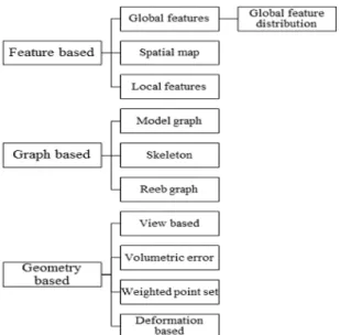
In this paper, the type of signature (or comparison mechanism) will depend of the type data and the level of details expected in the reverse engineering process. A methodological process of data signature is proposed, enabling to identify a component or an assembly in the heterogeneous data. The solution given relies on a dimensionless signature which is can be associated to global feature based of shape matching method (figure 1). It is detailed in the next sections.
3. FROM HETEROGENEOUS DATA TO DIGITAL MOCK-UP
Two research works are undertaken. The first one is dealing with knowledge encapsulation which enables to keep human skills such as a data base of a specific field. The second work is dealing to propose a
product model to design a digital mock-up from heterogeneous data. This section presents a preliminary work used in the national French project in order to propose a future product model. This will be used to support the methodological process below.
3.1. The METIS process
SADT diagrams presenting the general process have been the subject of a previous paper [7]. In this section a summary of the past diagrams and their evolution is suggested. The proposal brings a solution to elaborate a methodology in order to get back the digital mock-up of complex mechanical assemblies, made of several hundreds of parts. Considering the three use-cases enounced in the introductive section, the inputs and outputs of the process can be defined with the diagram below (first level of SADT):
Four types of input and output data are considered: (1) An optional initial 3D digital mock-up, made of CAD models and assemblies, complete or partial; (2) 2D and/or 3D digital data (points clouds, meshes, pictures, surfaces, etc.);
(3) Dimension-less socio-technical data (maintenance workbook, etc.);
(4) 3D digital mock-up with structured engineering bill of materials.
Then the next level is divided into 4 steps (Figure 3): - B1 consists in retrieving all the heterogeneous data and instantiate them the same in the METIS Management System solutions;
- B2 corresponds to data identification (component signature) which is the main subject of this work. It uses techniques of segmentation depending of the type of data. It enables then to match the different representations of a same component (picture, 3D
Figure 1 Taxonomy of shape matching methods [25]
B-0 To reverse from heterogeneous
data (1) (4) Enterpriseknowledge (2) (3)
Level of details Scenario Choice
CAD model, etc.). The output data of this step is encapsulated in a knowledge data base;
- B3 is similar with B2 but deals with extrinsic data such as functional surfaces between components and corresponds to the functional (assembly) signature; - B4 enables digital mock-up display: according to the level of details requested, there is a final multi-view mechanical assembly. This last step is not presented in this work and will be part of future ones.
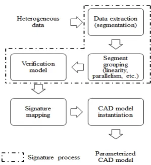
This paper relies on signature mechanisms in relation with data segmentation mechanisms. Learning from the SCERPO vision system [18], the identification step can be decomposed as in Figure 4. The first step relies on different techniques of segmentation depending of the type of data such as algorithms (Hough transform, Sobel Filter etc.).
The second step aims to group segments extracted according to properties.
The third one consists in searching and comparing similarities between the groups of segments extracted (edges of a shape in an image for example) and the
data in reference in the database (also called “signature of reference”). More specifically, it consists in comparing individually each “group of segments” with each signature in reference in the database and verifying if it corresponds or not to a mechanical component.
Once the shape is matched, the fourth step enables to combine information from all signatures concerning a same component. Depending of the set of heterogeneous data, a component can be identified in different formats (image, CAD model, points cloud). To finish, dimensional and topological information retrieved enable to instantiate a CAD model template which corresponds to the recognized mechanical component. The characteristics extracted from segmentation enable to deduce the values of the CAD model parameters.
The approach is in fact a progressive refinement from sources of knowledge database in order to find the family and technological component (or assembly) of the object to be reversed. Once we don’t have any data in input to be then exploited, we can launch the identification of the values of parameterized CAD and build the CAD BOM.
The signature process which is addressed in this paper needs to be defined considering the context of the study.
The first conceptual model enables to structure a Graphical User Interface which will illustrate the three processes presented in this section.
Taxonomy of our process is proposed in the next section thanks to a conceptual model.
B2 To identify data B3 To design BOM B4 To visualize digital mock-up B1 To import data (1) (4) Identified data Positionned data Classified data set Different types of data Important quantity of data
Choice of the final result (cao, assembly/part envelop) Information of hierarchical
organization between parts assembly
(3) (2)
(a)
Level of details Scenario Choice
(a)
(a)
(b) (a): internal algorithm
(b): external process BOM : bill of materials
Functional links between data
Figure 3 SADT diagram - level B0.
7 Marina Bruneau, Alexandre Durupt, Lionel Roucoules, Jean-Philippe Pernot, Harvey Rowson
3.2. Conceptual model of using
signature in METIS
A conceptual model has been done (Figure 6) in order to define the main concepts of METIS and their links between them.
(1) CAD Template: the knowledge database contains all the parts that can be identified. Before starting to use the process, we consider a step of knowledge capitalization during which the user would give all the expertise information to fill the database. These
templates are CAD models, they can be
parameterized or not.
(2) Component assembly or part: it is an elementary entity such as in Product Data Management applications. An assembly can have several parts (composition link). Each component is linked with a specific representation (CAD Template) and a signature associated to each type of data.
(3) Signature: it is defined as a set of characteristics which enable to describe an object. As an object can be represented by several media (sources), it can have several signatures. Moreover, in a media, the same object can have many signatures.
(4) Heterogeneous data: it is the data in input of the process as defined in Figure 2. In some use-cases, an initial Digital Mock-Up (DMU) can exist. Each heterogeneous data has an associated signature. (5) DMU or part: it is the data in output of our process, depending of the level of details requested and the user’s need. The DMU can be multi-views:
different visualizations corresponding to the
expertise.
Then, two main processes relying on the concepts defined previously could be identified. The first one deals with signature (Figure 5).
Each data (heterogeneous) is associated to a signature for each type required (text, image, points cloud, etc.).
The second process (Figure 7) deals with the identification of the data which methods relies on searching and comparing signatures.
Figure 5 Process of signature for heterogeneous data Figure 6 Conceptual model of METIS
1
2
3
4
Considering the comparison between two signatures of the same type (points cloud for example), this process output is a score which gives a similarity rate between the signature of the data (in input) and the signatures existing in the database. This first conceptual model enables to structure a Graphical User Interface which will illustrate the two processes presented in this section.
3.1. Signature of heterogeneous data
The signature process presented in this paper relies on one of the numerous shape matching methods called “global feature based method”. Most of the criteria rely on the isoperimetric inequality which
ensures that 36 in the case of continuous
space as related by Montero and Bribiesca [21]. In our case, the criterion chosen is called “compactness measure of a shape” and it is part of isoperimetric ratio (Parker et al. [22]).The main advantage lies in its invariance with the scale and orientation of mechanical components. It is a dimensionless number representing the degree to which a shape is compact.
Let D a 3D given data (CAD part or 3D mesh) of ℜ,
the sum of the area of its faces and , the
volume of its oriented bounding box. We define the compactness measure (shape factor) of D to be the number:
. ⁄ (1)
The units used for the area and the volume are
respectively in mm² and mm3. The bounding box
oriented is built thanks to the part’s inertia axis. Planes are created by intersection between each direction of each inertia axis and extremum points of the part.
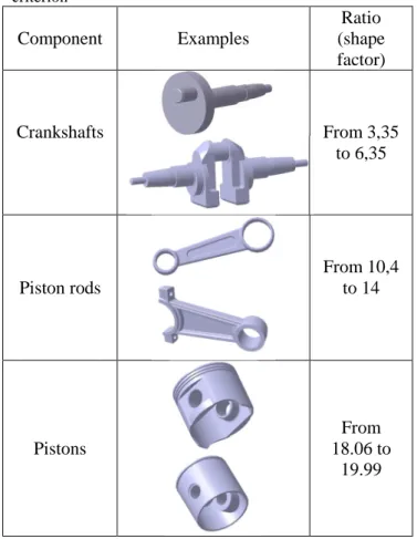
By applying our formula (1), the results in the Table 1 are obtained thanks to three families of components: crankshafts, piston rods and pistons.
Table 1 Component signature according to isoperimetric criterion Component Examples Ratio (shape factor) Crankshafts From 3,35 to 6,35 Piston rods From 10,4 to 14 Pistons From 18.06 to 19.99 4. APPLICATION
A real case study has been chosen in order to work on possibilities of post-production transformations by cutting costs (postponing differentiation). The case study considered is the engine of a French car engine. The heterogeneous data available are: (1) pictures of engine with several points of view; (2) 3D mesh of the engine (from points cloud). The use-case “from scratch” is considered because we assume that it is the most restrictive (it means that this use-case starts without initial digital mock-up). The expected result of the process is to get back a DMU of the engine with the ability to modify the parameters of the pulley (diameter, thickness etc.) and the alternator. The scenario implies that the knowledge database owns expertise information needed for data processing. An illustration is given on figure 8.
9 Marina Bruneau, Alexandre Durupt, Lionel Roucoules, Jean-Philippe Pernot, Harvey Rowson There are different states for the data and operations
(1-2-3) applied to go from one to the other step. The two main steps can be defined by signature whose two types can be: geometric and shape one and
functional one corresponding respectively to
component and assembly characterizations.
4.1. Graphical User Interface
presentation
A Graphical User Interface (GUI) has been developed by DeltaCAD, a company of software edition, in order to illustrate the concept of Metis. In the figure 9, a heterogeneous data have been imported and displayed.
The (1) zone corresponds to the list of data in input of our process. (2) is the part for data overview and result layout, relying on plugins implementation. The (3) area provides a bill of materials of the DMU in output. The command button allows identifying
heterogeneous data (signing, scoring and
identifying). In (4), the result of signature is displayed.
4.2. Illustration of the processes of
the conceptual model
To perform the signature, the user can select the data which have been linked manually (in white, in the right column). Indeed, we consider that the process has to be used in a specific context. For example, the user informs the system that a car engine is in processing, in order to limit research and comparison in the database. Then signature is realized “in context” and according of the type of the data. For the example below with a picture, Sobel and Canny filters and Hough transform have been used. These “internal processes” are performed thanks to plugins that METIS calls.
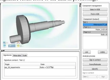
Another example is presented with a STL file (3D points cloud) of a crankshaft (figure 10). Data is signed using the isoperimetric criterion described in the section 3.1. On the right column, data are organized according to an engineering bill-of-materials and functional links are established between the three different parts (crankshafts, piston rods and pistons). The next step after signature is
Figure 8 Illustration of the case study in the whole process
Figure 9 Illustration of METIS GUI homepage
4 1
2
identification (research of components with a signature result close to the data in processing).
The system proposes different results with a score of similarity (Figure 11) which corresponds to the process of search and comparison signatures.
The unknown data signature is compared with the signature of the components in the database and the highest score obtained (the closest signature value) reveals the component identified.
4.3. Discussion
In one hand, the process proposed in this paper enabled to validate the scientific bolts identified in the national French project. Indeed, the state of the art and the decomposition showed the different shortage whether it is in software solutions or in literature. Moreover, this conceptual approach gave a first overview of the solutions that can be brought to perform the signature process.
In the other hand, the solution proposed is not exhaustive and several tests have to be done on different algorithms and type of data. The isoperimetric criterion, presented in this paper, is part of numerous others criteria which are more accurate
(with topological comparison for example). Another aspect is the notion of completeness of the data processed. Points clouds are often incomplete and have some holes which can cause incorrect result. In picture, there is the same problem, only one view of the component is found in the data.
5. CONCLUSION & PERSPECTIVES
This paper proposes an approach for a specific need in Reverse Engineering which is generally used to get back the 3D geometrical model of a unique physical data. This problematic comes from an industrial need in the automotive field whose aim is to deal with digital mock-ups of more than a hundred of components.
In this paper, a conceptual model is proposed in order to extract geometrical mark from the heterogeneous data thanks to segmentation and to identify mechanical components. “Signature” process plays a key role in the identification and it is considered as a set of characteristics allowing describing an object. The continuation of this study will articulate around the development of signature algorithms for each type of heterogeneous data. Moreover, the distance between signature (input data signed and referent signature) and the problem with incomplete data need to be studied accurately in order to improve data identification.
ACKNOWLEDGMENTS
These works have been supported by the ANR (National Agency of Research) through the Numerical Model program (Project METIS – 12-MONU-004).
REFERENCES
[1] Alrashdan, A., Motavalli, S. and Fallahi, B. (2000) ‘Automatic segmentation of digitized data for reverse engineering applications’, IIE Transactions, Vol. 32, No. 1, pp.59–69.
[2] ANR ARA MMSA 0001, (2005), EROS 3D, French project, Technical report, http://eros3d.ensea.fr/.
[3] ANR BLANC SATTIC (Strings and Trees for Thumbnail Images Classification), (2007), French project. Technical report http://www.agence-
nationale-recherche.fr/projet-anr/?tx_lwmsuivibilan_pi2%5BCODE%5D=AN R-07-BLAN-0317.
[4] Bénière, R., Subsol, G., Gesquière, G., Le Breton, F., Puech, W., (2013), “A comprehensive process Figure 10 Illustration of the process of signature
Figure 11 Illustration of the process “search and comparison signatures
11 Marina Bruneau, Alexandre Durupt, Lionel Roucoules, Jean-Philippe Pernot, Harvey Rowson
of reverse engineering from 3D meshes to CAD models”, Computer-Aided Design, Volume 45, Issue 11, pp. 1382–1393.
[5] Bespalov D, Regli WC, Shokoufandeh, (2003), “A. Reeb graph-based shape retrieval for CAD”, Proceedings of the ASME DETC 03 Computers and Information in Engineering (CIE) Conference, Chicago, IL
[6] Bin, L., Samiei M., (2012), “Comparison for Image Edge Detection Algorithms”, IOSR Journal of Computer Engineering, 2278-0661 Volume 2, Issue 6, pp 01-04
[7] Bruneau M., Durupt A., Roucoules L., Pernot J.P., Eynard B., (2013), “Towards new processes to reverse engineering digital mock-ups from a set of heterogeneous data”, Proceedings of the Ingegraph- ADM- AIP Primeca Conference, Madrid, Spain
[8] Canny, J., (1986), “A Computational Approach to Edge Detection”, IEEE Transactions on pattern analysis and machine intelligence, Volume 8, Issue. 6, pp. 679-698.
[9] Casey, R.G., Lecolinet, E., (1996), “A survey of Methods and strategies in Character Segmentation”, Transactions on Pattern Analysis and Machine Intelligence, Volume. 18, Issue 7, pp 690-706.
[10] Duda, R.O., Hart, P.E., (1971), “Use of the Hough Transformation to Detect Lines and Curves in Pictures”, ACM, Volume 15, Issue 01, pp. 11-15.
[11] Falcidieno, B., Giannini, F., “Automatic recognition and representation of shape-based features in a geometric modeling system”, (1989), Computer Vision, Graphics, and Image Processing, Volume 48, Issue 1, pp 93–123 [12] Heath, M., Sarkar S., Sanocki, T., Bowyer, K.,
(1998), “Comparison of Edge Detectors”, Computer vision and image understanding, Vol. 69, No. 1, pp. 38–54
[13] Herlem, G., Adragna, P.-A., Ducellier, G., Durupt, A. (2012), “DMU maturity management as an extension of the core product model”, Proceedings of the International Conference on Product Lifecycle Management, Volume 388 AICT, 2012, pp 192-201
[14] Hoffman, R.L., Jain, A.K., (1987), "Segmentation and classification of ranges images", IEEE transaction on pattern analysis and machine intelligence, No. 19, pp606-620
[15] IMASEG3D (Learning to combine hierarchical image modeling with 2-D segmentation and 3-D
pose recovery of visual objects) – Project finished in 2012. Technical report, http://users.isr.ist.utl.pt/~gcarneiro/mariecurie.ht ml
[16] Iyer, N., Jayanti, N., Lou, K., Kalyanaraman, Y., Ramani, K.,(2005), “Three-dimensional shape searching: state-of-the-art review and future trends”, Computer-Aided Design 37, 509–530 [17] Kalyanapasupathy V, Lin E, Minis I., (1997),
“Group technology code generation over the internet”, ASME Design Engineering Technical Conferences, Sacramento, CA
[18] Lowe, D.G., (1987), “Three-Dimensional Object Recognition from Single Two-Dimensional Images” Artificial Intelligence, pp 355--395 [19] Mehdi-Souzani, C., Digne, J., Audfray, N.,
Lartigue, C., Morel, J.-M., “Feature Extraction from High-density Point Clouds: Toward Automation of an Intelligent 3D Contactless Digitizing Strategy”, (2010), Computer-Aided Design and Applications, Volume 7, Issue 6, pp. 863-874
[20] Meyer, A. and Marin, P. (2004) ‘Segmentation of 3D triangulated data points edges constructed with C1 discontinuous surface fitting’, Computer Aided Design, CAD’04, Vol. 36, No. 4, pp.1327– 1336.
[21] Montero R.S. and Bribiesca, E., (2009), ‘State of the Art of Compactness and Circularity Measures’, International Mathematical Forum, Volume 4, Issue 27, pp. 1305-1335
[22] Parker K.J., Marjatta S., Totterman S., Pena J.T., ‘System and method for 4d reconstruction and visualization’, Patent No US 6,169,817 B1, University of Rochester (NY)
[23] Sapidis, N. and Besl, P. (1995) ‘Direct construction of polynomial surfaces from dense range images through region growing’, ACM Transactions on Graphics, Vol. 14, No. 2, pp.171–200.
[24] Shrivakshan, G.T., Chandrasekar, C., (2012), “A Comparison of various Edge Detection Techniques used in Image Processing”, International Journal of Computer Science Issues, Vol. 9, Issue 5, No 1, pp 269-276.
[25] Su, J., Srivastava, A., Huffer F. W., (2013), “Detection, classification and estimation of individual shapes in 2D and 3D point clouds”, Computational Statistics & Data Analysis, Volume 58, pp. 227–241
[26] Sunil, V. and Pande, S. (2008) ‘Automatic recognition of features from freeform surface
CAD models’, Computer-Aided Design, Vol. 40, No. 4, pp.502–517.
[27] Tangelder, J., Veltkamp, R., (2007), “A Survey of Content Based 3D Shape Retrieval Methods”, Multimed Tools Application, Volume,39, pp 441–471
[28] Thompson, W. B., Owen, J., de St Germain, H.J., Stark, S.R. and Henderson, T. (1999), ‘Feature-based reverse engineering of mechanical parts’, IEEE Transactions on Robotics and Automation, Vol. 15, No. 1, pp.57–66.
[29] Urbanic, R., Elmaraghy, H. and Elmaraghy, W. (2008) ‘A reverse engineering methodology for rotary components from point cloud data’, International Journal of Advanced Manufacturing Technology, Vol. 37, Nos. 11–12, pp.1146–1167. [30] Varady, T., Martin, R. R., Coxt, J., (1997),
“Reverse Engineering of geometric models-an introduction”. In Computer-Aided Design, Vol. 29, No 4, pp. 255-268
[31] VPERI, "Virtuals Part engineering Research Initiative, The final report, www.cs.utah.edu/gdcNiper/collaborationNPERIF inal report.doc, (2003).
[32] Yokoya, N., Levine, M., (1989),"Range image segmentation based on differential geometry: A hybrid approach", IEEE transaction on pattern analysis and machine intelligence, No.11, pp643-9
[33] Zhou, Z., Zheng, L., Xia, J., Yang, W., Lei, J., (2010), “Image Edge Detection Based on Improved Grey Prediction Model”, Journal of Computational Information Systems, Volume 6, Issue 5, pp. 1501-1507