for High Speed Links
by
Maxine Lee
S.B. EE, M.I.T., 2005
Submitted to the Department of Electrical Engineering and Computer Science
in Partial Fulfillment of the Requirements for the Degree of
Master of Engineering in Electrical Engineering and Computer Science
at the Massachusetts Institute of Technology
September, 2006
@2006
Massachusetts Institute of Technology
All rights reserved.
A u th o r ... ...
...
Department of Electrical Engineering and Computer Science
September 8, 2006
Certified by ...
...
Vladimir Stojanovic
Assistant Professor of Electrical Engineering
M.I.T. Thesis Supervisor
A ccep ted b y ...
Arthur C. Smith
Professor of Electrical Engineering
Chairman, Department Committee on Graduate Theses
Channel-and-Circuits Aware, Energy-Efficient Coding for High Speed Links by
Maxine Lee
Submitted to the
Department of Electrical Engineering and Computer Science September 8, 2006
In Partial Fulfillment of the Requirements for the Degree of Master of Engineering in Electrical Engineering and Computer Science
at the Massachusetts Institute of Technology
Abstract
Throughput and energy-efficiency of high-speed chip-to-chip interconnects present critical bot-tlenecks in a whole range of important applications, from processor-memory interfaces, to network routers. These links currently rely solely on complex equalization techniques to maintain the bit error rate lower than 10-1. While applicable to data rates up to 10 Gb/s on most links, this approach does not scale well to higher data rates or better energy-efficiency. The work described in the thesis shows that it may be possible to use coding techniques to share the burden of combating errors, while increasing the throughput of the link or improving its energy-efficiency. Since codes here attempt to alleviate the impact of partially correlated sources of error (like reflections interference, crosstalk and jitter), an experimental setup was created for characterization of link channel properties and per-formance gains from different codes. Four codes, specifically Hamming, BCH, Fire, and SEC-DED codes, are implemented and analyzed with various configurations (i.e. different blocksizes, data rates, and detection or correction). Most significantly, it is discovered that detection and retransmission of even the simple codes implemented in this project may be able to maintain a bit error rate of 10-1.
Thesis Supervisor : Vladimir Stojanovic
Acknowledgments
First and foremost, thank you to my research advisor, Vladimir Stojanovic, for his continued sup-port throughout my graduate career, and whose technical prowess and dedication to the field are truly remarkable and inspiring.
To my colleagues in the Integrated Systems Group, Natasa Blitvic, Byungsub Kim, Ranko Sredojevic, Sanquan Song, and Fred Chen, thanks for making our lab such an enjoyable environment. I could not have asked for more intelligent, fun, and fascinating people to drink coffee with and to spend all those long days and nights with.
To my best friends at MIT, especially David Vincent, my greatest supporter, and Wendy Chang, my coffee buddy and roommate, thanks for making my entire college experience amazing.
Finally, thank you to my parents for getting me started on the right track and letting me find my way. I would not be where I am today without the values and morals you ingrained in me and all of your advice throughout the years.
Contents
1 Introduction 8
1.1 T he P roblem . . . .. 8
1.2 The Proposed New Technique . . . . 10
2 Background 11 2.1 Basic Coding Theory . . . . 11
2.1.1 Linear Block Codes . . . . 12
2.2 Types of Errors . . . . 14
2.3 The Binary Symmetric Channel (BSC) Model . . . . 15
2.4 Coding System s . . . . 16
2.4.1 Forward Error Correction (FEC) . . . . 16
2.4.2 Automatic Repeat Request (ARQ) . . . . 16
2.4.3 Hybrid Forward Error Correction / Automatic Repeat Request . . . . 17
2.5 K now n Codes . . . . 17
2.5.1 Hamming Codes . . . . 18
2.5.2 Bose, Chaudhuri, and Hocquenghem (BCH) Codes . . . . 19
2.5.3 F ire C odes . . . . 19
2.5.4 Single-Error-Correcting, Double-Error-Detecting (SEC-DED) Codes . . . . 20
2.5.5 Cyclic Redundancy Check (CRC) . . . . 21
3 Previous Work 22 4 Problem Statement 22 4.1 Purpose of the Work . . . . 22
4.1.1 Limitations in Current Methods in Link Transmissions . . . . 22
4.1.2 The Goal of This Work . . . . 23
4.1.3 Limitations in Previous Methods in Link Coding . . . . 24
4.2 Simultaneous Work and Future Plans for Link Coding . . . . 25
5 Methodology 27 5.1 Description of Hardware . . . .. . . . . 27
5.1.1 Virtex I-ProXFPGA. . . . . .. . . . . 27
5.1.2 RocketIO X Transceivers . . . .. . . . . 28
5.2 Desired Information to Capture . . . . .. . . . . 29
5.3 Line Cards and Backplanes . . . .. . . . . 30
5.4.1 PRBS Generator . . . . 5.4.2 Transm itter . . . . 5.4.3 Receiver and Statistics Gatherer . . . . 5.4.4 Software System . . . . 5.5 Codes Implemented . . . . 5.5.1 Sim plifications . . . . 5.5.2 Hamming Codes . . . . 5.5.3 BCH Codes . . . . 5.5.4 Fire C odes . . . .
5.5.5 Single Error Correction, Double Error Detection (SEC-DED) .
5.6 Encoder D esign . . . .
5.7 D ecoder D esign . . . .
6 Results
6.1 Tuning the Equalizer and Choosing Data Rates . . . .
6.2 Results Compared to a Binary Symmetric Channel . . . .
6.3 Uncoded Results . . . .
6.3.1 Number of Errors Per Word for Each Data Rate and Block Size
6.3.2 Error Lengths for Each Data Rate and Block Size 6.4 Coded Results . . . .
6.4.1 Simplifications and Approximations Used for Generating 6.4.2 Results for Hamming Codes . . . . 6.4.3 Results for SEC-DED Codes . . . . 6.4.4 Results for BCH Codes . . . . 6.4.5 Results for Fire Codes . . . . 6.4.6 Results for More Powerful BCH and Fire Codes . . . . .
6.5 Code Comparison . . . .
6.6 Remarks on Hardware Requirements of Codes . . . .
6.7 Alternative Codes that May Yield Good Results . . . . 7 Conclusion
7.1 Recommendation for Future Work . . . .
7.2 Final Recommendation . . . . Results 32 33 35 39 41 42 42 43 44 45 46 47 49 49 50 51 51 52 54 55 56 60 62 65 67 68 71 71 72 73 74
. . .
.
.
.
.
List of Figures
High-Speed Link Channel Diagram . . . . A Typical State-of-the-Art Transceiver Cell . . . . A Received Pulse After the Link Effects . . . . LFSR for Encoder Implementation . . . . Binary Symmetric Channel (BSC) Model . . . . Laboratory Setup... ...
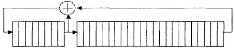
Different Materials Used in Backplanes: Rogers, NELCO, FR4 . . . . High Level Block Diagram . . . . LFSR Implementation for the PRBS generated by g(X) = X3 1 + X8 + 1. .
Transmitter Block Diagram . . . . Transmitter Finite State Machines . . . . Receiver Block Diagram . . . . Receiver Finite State Machines . . . . RAM Connections to Create a Histogram . . . . Cycle-by-Cycle Example of Creating a Histogram Using a RAM . . . . Encoder Circuit for the Last Parity Bit in the (40,34) Hamming Code . . . A Generic Encoder for a Code with More Than 40 Bits . . . . D ecoder Circuit . . . . Link Behavior at 5.5 Gb/s, 6 Gb/s, and 6.75 Gb/s . . . . Distribution of Errors Per Word at 6 Gb/s and 6.25 Gb/s . . . . Distribution of Error Lengths at 6.25 Gb/s on a Rogers Link . . . . Data Dependency of Coded Hamming Data Stream at 6 Gb/s . . . . Data Dependency of Coded Hamming Data Stream at 6.25 Gb/s . . . . Hamming (40,34) and (80,73) Correction Results . . . . Effectiveness of Hamming Codes for N =40, 80, or 1000 and Data Rates of SEC-DED (40,33) and (80,72) Correction Results . . . .
8 9 9 . . . . 14 . . . . 15 . . ... 27 . . . . 30 . . . . 31 . . . . 32 . . . . 33 . . . . 34 . . . . 35 . . . . 36 . . . . 39 . . . . 40 . . . . 46 . . . . 47 . . . . 49 . . . . 51 . . . . 52 . . . . 53 . . . . 57 . . . . 57 . . . . 58 6 and 6.25 Gb/s 59 . . . . 61
Effectiveness of SEC-DED Codes for N =40, 80, or 1000 and Data Rates of 6 and 6.25 Gb/s 63 Effectiveness of BCH Codes for t = 2, N =40, 80, or 1000, and Data Rates of 6 and 6.25 G b /s . . . . 64
Data Dependency of Coded Fire Data Stream . . . . 65
Effectiveness of Fire Codes for 1 = 4, N =40, 80, or 1000, and Data Rates of 6 and 6.25 Gb/s 66 Effectiveness of the (480,435) BCH Code and the (480,425) Fire Code at 6 and 6.25 Gb/s 67 Bit Error Rate Improvement For Each Code at 6 Gb/s . . . . 69
List of Tables
1 PowerPC Address Space . . . . 40 2 Bit Error Rate for Various Data Rates on a Rogers Link . . . . 50
1
Introduction
There is a constant struggle to keep up with the increasing demands in various applications requiring high-speed chip-to-chip interconnects, such as network routers and processor-memory interfaces. To increase data rates while maintaining reliability, new advances must be made in the techniques used for data transmissions through backplanes. Backplanes are used in router backbones, where multiple, densely compact channels are needed, each transferring data at very high speeds. The purpose of the work described in this document is to demonstrate the potential of a new approach to transceiver design: energy-efficient coding. This technique should help alleviate the current bottleneck in achieving higher data rates.
1.1
The Problem
A typical high-speed link channel consists of the components in Figure 1. This system is highly complex, due to various sources of impedances, short traces like stubs and vias which are susceptible to reflections, and longer traces which suffer from attenuation. Added on top of the channel effects are the wide range of noise sources that are non-additive white Gaussian (non-AWG), such as sampling offset, supply noise, and jitter [2]. The current technique for transceiver design involves opening the eye of the signal with complex transmit and receive equalizers. However, the complexity of the equalizer and the number of taps is severely limited by the high throughput and high energy-efficiency needed by the application. Thus, to maintain high reliability, data rate is sacrificed.
An example of such a transceiver implementation is shown in Figure 2 and is described further in [3].
Package- t
On-chip
parasiticttermination resistance and ickage
Line card trace device loading capacitance)
Back plane trace Back plane connector Line card
Backplane via
Anticsusa aItaps
Sampled
Deadband Feedback taps TXa Data ---)Channel
TapSel Causal Logic tp \ 4 4Figure 2: A Typical State-of-the-Art Transceiver Cell [3] 40 1 O
0.8
0.60.4
0.2
0 0 1 2 3ns
Figure 3: A Received Pulse After Link Effects [4]The purpose of the hardware is to apply signal processing techniques to cancel the symbol inter-ference (ISI), which is deterministic. There are two types of ISI caused by the channel. The first is dispersion ISI, illustrated by the widening of the pulse in Figure 3. The effects of dispersion are short, so only short-length filters are necessary to combat the errors. The signal, however, has smaller pulses a few nanoseconds after the initial pulse because of the second type of ISI, reflections. Reflections are caused by impedance mismatches between the various connectors of the system components in Figure 1. In order to combat these reflections, current methods dissipate a large amount of power.
To combat the ISI described above and pictured in Figure 3, the hardware must be very complex and powerful. A linear equalizer called a precoder is used on the transmitting side. At the most fundamental level, the precoder consists of a simple FIR filter. The taps are designed to reduce the effect of surrounding data bits on the current data point of interest. In this particular transceiver design, five equalizer taps are used. On the receiving end, a decision-feedback equalizer (DFE) is the standard equalizer architecture. For causal ISI, the DFE can subtract away errors from the bit entering the receiver. In the design, the receiver may use up to 17 taps to cancel a single bit.
At a bit error rate of 10-15, all of the required hardware burns a total of 40 mW/(Gb/s) and is only capable of operation at 10 Gb/s for 4-PAM signaling and 5-6.4 Gb/s for 2-PAM signaling. From the calculations made in [51, links should be capable of supporting data rates between 80 Gb/s and 110 Gb/s. The performance of the transceiver in [3] clearly falls short of this mark.
Finally, to illustrate the necessity of improved transceiver design, consider the result of using this state-of-the-art transceiver to create a 40 Tb/s crossbar router chip. Typical chips currently support 1 Tb/s, so 40 Tb/s is not an unrealistic increase. 4000 of the current 10 Gb/s transceivers would have to be used in the router chip to achieve the desired data rate. Since each transceiver uses a differential pair, this means that the chip would need 8000 I/O pins, requiring the total on-chip area to be 4000
mm2. The resulting switch card would be 160 inches wide and 100 inches long. Furthermore, since each
transceiver dissipates 40 mW/Gb/s, the power consumption for the crossbar chip would total 1.6 kW in 130 um CMOS technology [3].
Clearly, these results suggest that a completely new technique may be required in order to approach the theoretical capacity of links, and thus be able to create a 40 Tb/s router chip. At the very least, an order of magnitude increase in the energy-efficiency and the data rate of each transceiver is necessary. The ongoing research in high-speed links attempts to push the data rates to approach the full capacity of the link channel. For example, the advantageous parallelism of multi-tone techniques presented in [6] improves the achievable data rates significantly, but the results fall well short of the desired mark. Regardless of the modulation or equalization technique used, it is necessary to apply coding to approach full link capacity. The challenge is in doing so in an energy-efficient manner.
1.2
The Proposed New Technique
The proposed remedy to the current limitations in data rate is to add coding techniques. More specifi-cally, reflections may be considered a noise source and handled by the code rather than the equalizers. Reflections are only weakly correlated, so coding may be much more effective than signal processing tech-niques at elimination their effects. The equalizer's primary job would then be to combat dispersion ISI, which requires fewer taps. Thus, the complexity of the equalizers may be reduced as well as the amount
of power dissipated. From here on, this thesis will refer to reflections as a noise source and not as ISI. Another source of errors in link transmission not mentioned above is the signal interference caused by crosstalk. Because the signal paths in backplanes are so densely compact, the data of surrounding wires will affect the signal and possibly cause errors. Since crosstalk is not correlated with the data of interest, coding can also potentially address any issues caused by this source.
Until recently, coding for links has not seriously been considered, because the overhead required by coding and the added receiver latency appeared too difficult to surmount. Thus, it is the purpose of this work to show that there is definite potential in applying coding techniques. Existing codes are used to show that even codes not designed specifically for links can be advantageous if applied in the correct
manner. Furthermore, these existing codes provide hints as to what properties are particularly effective at tackling the non-AWG noise sources of links.
The results of this work will feed directly into future research, especially involving the design of codes created specifically to address link error characteristics and the design of transceivers that incorporate both equalization and coding.
2
Background
For the remainder of the document, it is necessary for the reader to have a basic knowledge of coding theory and the particular codes chosen for implementation in the project. Furthermore, much of the terminology used in the document is defined in the following subsections. The descriptions, however, are not mathematically thorough and are only intended to provide the reader with enough insight to under-stand the work involved in the project. For more in depth information on coding, especially concerning mathematical concepts and proofs, see
[7].
2.1
Basic Coding Theory
The purpose of coding is to increase the reliability of data transmission through a noisy medium. Some redundancy is added to the information in order to detect and possibly correct errors that occur through the channel. The typical metric for quantifying the reliability is the bit error rate (BER), defined by the
total bit errors that occur divided by the total bits sent through the channel. Thus, the objective of the code is to reduce the BER.
There are two main classes of codes: block codes and convolutional codes. Block codes segment the binary sequence of information bits into k-bit blocks and calculate the redundancy for each block separately. The k bits are each transformed into n bits, where n > k and m = n - k is the number of redundant bits. Convolutional codes also transmit
n
bits for every k bits, but the parity bits are generated serially. Convolutional codes typically have very high overhead, and are not well suited for binary modulation on band-limited channels. Therefore, this thesis is focused on relatively high-rate block codes.2.1.1 Linear Block Codes
An (n, k) block code is a code that transforms a message of k bits into a codeword of n bits. The ratio R = k/n is the code rate of the block code, and it is the fraction of the bits sent through the channel that carries actual information. A block code is termed linear if the sum of two codewords is another codeword, and the class of linear block codes is a large and powerful class of codes used in this project.
The Hamming distance, dmin, is an important metric for describing the resiliency of a code. The Ham-ming distance is the minimum number of errors that must occur for any one codeword to be transformed into any other codeword. Therefore, a code with a Hamming distance of three will be able to detect all single-bit errors and double-bit errors within the n-bit block, since the resulting block is not a codeword. For error correction, a t-error-correcting code must have a Hamming distance of 2t + 1 < dmin 2t + 2. For example, a code with dmin = 3 can correct all single-bit errors but not all two-bit errors, since a two-bit error may cause the block to more closely resemble a different codeword.
Generator and Parity-Check Matrices A code may be defined by a k x
n
generator matrix, G, or an m x n parity-check matrix, H, where m =n
- k. If the k-bit vector, u, represents the messagesequence, v = u - G gives the corresponding n-bit codeword vector. On the decoding side, the n-bit vector, r = v + e is received, where e is an error vector that contains a 1 at a position if an error occurred. Afterward, s = r -HT is computed, where s is called the syndrome of the vector. H is in the null space of
G, so the syndrome will be zero only if r is a codeword. For r to be a codeword, e must be a codeword. The all-zero error vector, which indicates that no errors took place, is itself a codeword. Therefore, we must assume that an all-zero syndrome indicates that no errors took place. Using this approach, an error will go undetected only if e is a non-zero codeword, and all errors for which e is not a codeword can be detected. (Note: For this reasoning, it is easy to see that higher-weight codewords are desirable, where the weight is the number of 1's in the codeword, so that the probability of an undetected error is lower. In fact, the Hamming distance is equal to the weight of the lowest-weight codeword)
There are 2
m
syndrome values for any given code, so if error correction is required by the system, thenat most 2' different error patterns, e, may be corrected. There are, however, 2" = 2
m
x 2k possible error patterns. Therefore, there are 2k error patterns that will cause the same syndrome value, and to maintain a high code rate, 2k is usually much greater than
2m.
The decoder does not have enough informationto distinguish between these 2k error patterns. The decoder essentially assumes that, given a non-zero syndrome, the error pattern with highest probability occurred, and it corrects r accordingly. If in fact a less probable error pattern caused the syndrome value, a correction error will occur.
A code is in systematic form if the codeword consists of the k information bits followed by the m parity bits. To generate a code in systematic form, the rightmost columns of G should be the k x k identity matrix. The remaining, leftmost columns describe how the information bits form the m parity bits. Thus, G = [P
Ikxk].
Similarly, for H to be in the null space of G, the leftmost columns of H must then be the m x m identity matrix, and therefore H = [Imxm P'J.Cyclic Codes Many important linear block codes are cyclic, which means that shifting any codeword produces another codeword. Cyclic codes can be described simply by a generator polynomial, g(X) =
1+aoX +a2X2+ ... + amXm, where the ai's take on binary values. All codewords in the code are divisible
by the generator polynomial, so the syndrome can be obtained by merely dividing the received vector by
g(X).
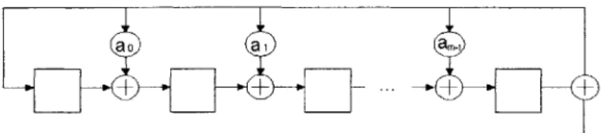
Cyclic codes are especially useful because they can be encoded and decoded simply using linear feedback shift registers (LFSRs). The feedback connections are specified by g(X) (see Figure 4). The tradeoff in using this type of implementation is speed, for it takes k clock cycles at the encoder to create
ao
ai
a,
+
+
..
+
Figure 4: A simplified LFSR that generates the m parity bits for a cyclic code with g(X) = 1 + a0X + a2X
2
+ ... + am-iXm-l. a2 is a wire when ai = 1. Otherwise, it is an open circuit. At the encoder, with all the registers initially set to zero, the information bits are fed into the bottom right serially. After all
k information bits have been shifted in, the register contains the m parity bits.
the parity digits, and n clock cycles at the decoder to generate the syndrome digits (plus additional cycles for error correction, if necessary).
Shortened Codes Many widely used codes are specified for a particular n and k. However, different applications may require block sizes other than the one specified. It is always possible to create a (n-1,
k-1) block code by removing I columns from the parity-check matrix, and adjusting the generator matrix
accordingly. This new, shortened code has at least the error detecting and correcting capability of the original code, and often performs better at the expense of a decreased code rate.
Also, it is simple to create a (n-1, k-1) shortened cyclic code. A shortened cyclic codes may be generated using the same circuitry as the one used for the original cyclic code with only minor alterations in the decoder. Since shortening a cyclic code is equivalent to removing all codewords with I leading zeros, the resulting codewords are no longer cyclic. In general, a code can be shortened by deleting any columns of the parity-check matrix other than the columns that make up the m x m identity matrix. However, to keep the same hardware as the original cyclic code, the last 1 columns of the code's corresponding parity-check matrix must be deleted.
2.2
Types of Errors
There are two general types of errors that may occur during transmission: burst errors and random errors. Errors are considered bursty if there are multiple errors that occur within some reasonably short length. Thus, the following error patterns are bursty with a burst length of 6: 100001, 110001,..., 111111. Burst errors occur when the errors are correlated. For example, compact discs are often subject to burst errors,
1-p
1
1
1
- p
Figure 5: Binary Symmetric Channel (BSC) Model
since scratches are likely to affect multiple information bits in a row.
On the other hand, if there is no correlation between bit errors, then the errors are random. If all bit errors are independent, using the binomial distribution, it is easy to see that the probability of a higher-weight error pattern occurring is less than that of a lower-higher-weight error pattern. Thus, for a channel with random-errors, it is beneficial to correct low-weight error patterns. The Hamming distance of a code is therefore the proper metric to judge the strength of the random-error-detecting/correcting ability of code. Clearly, increasing the Hamming distance of a code is not the proper way to reduce the BER of a burst-error channel. Instead, burst-burst-error-correcting and burst-burst-error-detecting codes are designed to correct or detect a particular burst length. The Hamming distance is usually not specified in these types of codes, since the particular number of errors in the block is not the concern. Thus, a burst-error-detecting code with length seven correction ability can correct all error patterns of error length seven, but may not be
able to correct a 2-bit error separated by eight bits.
It is also possible to design a code that has both random-error and burst-error detection and correction properties. Often times, this is accomplished by combining a code of a particular Hamming distance with a code of a particular burst-error-correcting length. As expected, the code suffers from a lower code rate.
2.3
The Binary Symmetric Channel (BSC) Model
A simple and commonly used channel model is the binary symmetric channel (BSC) model (Figure 5), which applies only when the probability of a bit error is independent of all other bits transmitted and the error probability is constant for all bits. In a BSC, the probability of an error occurring for any given bit is p, the BER.
on a single variable, the BER, which can be easily calculated experimentally. Furthermore, it would be particularly easy to set up an accurate simulation environment to test different codes. In fact, the performance of many codes has already been studied for a BSC, so choosing the right code for the application is dramatically simplified. Finally, random-error-detecting/correcting are most effective over BSC channels, so if the channel is binary symmetric, it is clear that coding will be effective.
2.4
Coding Systems
In order to capitalize on coding techniques, the codes must be implemented in some error correction protocol. In a real transmission system where the purpose is to correctly receive transmitted data, it is useless for the receiver to be able to detect an error if it is not able to utilize this knowledge to obtain the correct data. Thus, error-detecting codes must be used in conjunction with other techniques. The following sections describe techniques for error correction using codes that detect, correct, or can simultaneously do both.
2.4.1 Forward Error Correction (FEC)
A forward error correction system uses the most straightforward strategy. FEC systems utilize only the error correcting capability of codes. The transmitter sends a codeword through the channel, and the receiver attempts to correct any errors that occurred during transmission. The output of the decoder is then sent to the destination.
2.4.2 Automatic Repeat Request (ARQ)
An automatic repeat request decoder does not attempt to correct errors that occur in transmission, but instead asks for the data to be retransmitted until the block is correctly received. Thus, ARQ protocols only rely on error detection.
Automatic repeat request systems require both a forward channel and a back-channel. The transmitted data is sent through the forward channel. Once a codeword is received and decoded, the receiver transmits either a positive acknowledgment (ACK) or a negative acknowledgment (NAK) to the transmitter through the back-channel. A NAK signals to the transmitter that an error has been detected. Once a NAK is
received, the transmitter queues the corresponding word for retransmission.
Since only error detection is required, the only way for the destination to receive incorrect information is if an undetected error occurs. ARQ systems are often preferred to FEC systems, since error detecting codes require much less hardware, and error detection is much more reliable than error correction.
There are multiple types of ARQ protocols that trade off throughput and complexity. The delay through a high speed backplane is short enough such that ARQ systems have very high throughput. A typical 20 inch backplane has a round trip delay of approximately 100 symbols. The different types of ARQ systems are not studied in this project, so the reader is referred to Chapter 22 of [7] for an introduction to the different types.
2.4.3 Hybrid Forward Error Correction / Automatic Repeat Request
As suggested by the name, hybrid FEC/ARQ schemes utilize both error correction and detection with retransmission. In general, the most common errors are corrected. The less frequent errors, which may be mis-corrected if correction were attempted, are left for retransmission. Using a hybrid scheme requires further code examination, since the object of the code is no longer to maximize either correction or detec-tion capability, but to find a compromise between the two. With simultaneous error detecdetec-tion/correcdetec-tion, the more error patterns the code attempts to correct, the fewer error patterns it will be able to detect overall. Thus, there is a tradeoff as to how much correction should be attempted.
2.5
Known Codes
A wide range of codes with varying capabilities are used in the project. Few errors per block are expected, so these codes are chosen for their lower error correcting or detecting ability and high code rate. The codes studied are Hamming, BCH, Fire, SEC-DED, and CRC codes. Specifically, Hamming codes have high rate and are capable of correcting the most common type of errors, single-bit errors, and detecting double-errors. BCH codes extend the correcting capability by one bit error and the detecting capability by two bits, since multiple errors per word happen relatively frequently. Fire codes are burst-error-correcting codes, so they provide insight into the effectiveness of burst-error-correction in links. SEC-DED codes
are a common, high rate code designed especially for hybrid FEC-ARQ systems. Finally, CRCs are cyclic codes that are used strictly for detection in ARQ schemes. More detailed descriptions of each class of codes follows.
2.5.1 Hamming Codes
Hamming codes are a very popular class of codes used for single-error-correction. Hamming codes are desirable, because they have a very simple structure and a high code rate. They are used in forward error correcting schemes when the errors are random and the error rate is low. The same code, if desired, may also be used instead for double-error detection.
Code Structure For a given number of parity bits, m, Hamming codes have a block size of n = 2' _
I
for m > 2. Thus, the Hamming codes with the shortest block sizes are the (7, 4), (15, 11), and (31, 26) codes.A Hamming code has a parity-check matrix of size m x (2' - 1). The 2
m
- 1 columns consist of all the non-zero combinations of m bits. Assuming the Hamming code is in systematic form, the first m columns consist of the m x m identity matrix. This leaves the remaining k =n
- m columns with all the combinations of weight-two or greater.Hamming codes may also be cyclic. Cyclic Hamming codes are generated using a primitive polynomial of degree m.
Code Properties The Hamming distance of a Hamming code is precisely three. This can be seen by examining the parity-check matrix and knowing that the Hamming distance of a code is equal to the number of columns of H needed to sum to zero (see [7] for a proof). Since all 2
m
-1 non-zero combinationsof m bits are used as the columns, adding any two columns together will always give the value of another column. Thus, the modulo-2 sum of these three columns gives a zero vector.
Since the Hamming distance is three, the code is able to correct all single-bit errors. Furthermore, Hamming codes are one of a few known perfect codes. There are exactly n error patterns of single weight and exactly 2
m
- 1 = n non-zero syndrome values. Thus, every syndrome value can be used for single-biterror correction. This is especially useful for FEC, since the code essentially takes full use of all the redundancy.
The Hamming distance of three also means that the same codes can be implemented to detect all errors of weight one or two. Thus, Hamming codes can be used in an ARQ system.
2.5.2 Bose, Chaudhuri, and Hocquenghem (BCH) Codes
Bose, Chaudhuri, and Hocquenghem (BCH) codes are a class of t-error-correcting codes ( [8], [9] ). When t = 1, BCH codes reduce to Hamming codes. There are a number of different types of BCH codes, and not all of them are binary. Reed-Solomon codes, for example, are a commonly used subclass of BCH codes that are nonbinary. Due to the complexity, and therefore lower energy-efficiency, involved with non-binary BCH codes, the only codes of interest in the project are binary, primitive BCH codes.
Like Hamming codes, the block size of BCH codes are 2" - 1. The number of parity-check digits required, however, is at most mt, where t is the number of bit errors the code can correct. For most block sizes of interest, the number of parity bits required is exactly mt.
Further discussion on the structure and properties of BCH codes is omitted, since BCH codes are constructed using mathematical tools in fields greater than GF(2) (i.e. non-binary). For more information on BCH codes, the reader is referred to [7].
2.5.3 Fire Codes
Fire codes are the first class of systematically constructed single-burst-error correcting codes. Fire codes also have good burst-detecting cap
Code Structure A Fire code with a burst-error-correction length of 1 is generated by g(X) = (XC +
1)p(X), where c = 21 - 1. The polynomial, p(X) is an irreducible polynomial of degree m, where I < m.
Define p to be the smallest integer such that p(X) divides XP + 1. Then c cannot be divisible by p, and n = LCM(c, p).
Code Properties To generalize the definition given above, a Fire code is actually able to simultaneously correct bursts of length I and detect bursts of length d for d >
1
according to the equation, c > 1 + d - 1. Thus, the definition given in the previous section is the special case for obtaining the Fire code with greatest burst-error-correcting length. If the correction requirement is relaxed, the detecting capability of the code expands. On the far extreme, if only detection is used for an ARQ protocol, a Fire code isactually capable of detecting all bursts of length c + 1.
2.5.4 Single-Error-Correcting, Double-Error-Detecting (SEC-DED) Codes
The class of codes for single error correction and double error detection (SEC-DED) was first proposed by Hamming in [10] and later refined by Hsiao [11]. They are suited particularly well for hybrid FEC/ARQ systems. SEC-DED codes are designed specifically for obtaining high memory reliability in computers.
Code Structure SEC-DED codes are constructed by appropriately shortening Hamming codes in such a way that the Hamming distance is increased to four. First, all even-weight columns in the parity-check matrix are removed. Afterward, to reach the required block size, odd-weight columns of largest weight are removed. These large-weight columns are removed in such a way that the final parity-check matrix has the same number of
1's in each row, or as close to the same as possible.
Code Properties The Hamming distance of four guarantees that the code can always accurately correct single errors and detect double errors. If a single error occurs, the received vector will always be closest to the actual codeword, and correction can remove the error. If two errors occur, the received vector may be most similar to multiple codewords, so the errors can only be detected.
To see that the Hamming distance is four, we note that even-weight syndromes (like the zero-vector) must result from adding an even number of distinct, odd-weight columns from the parity-check matrix together. This, combined with the fact that the Hamming distance must be at least that of the Hamming code, from which the SEC-DED code is derived, means that the Hamming distance is at least four.
Another valuable property that results from using odd-weight columns is ease in determining whether to apply correction or detection on a received vector with a non-zero syndrome. If the syndrome is
odd-weight, an odd-weight error pattern must have occurred. The decoder assumes that a single error occurred, and it attempts to correct the received vector. If the syndrome is even-weight, then at least two errors have occurred, so only retransmission is possible.
SEC-DED codes are designed for encoding and decoding the entire codeword in parallel. For this reason, the algorithm creates a parity-check matrix with a minimum number of I's and an even distrib-ution of
1's
between the rows. These two requirements guarantee that minimum logic levels are used in calculating each syndrome bit, allowing for faster clock speeds.2.5.5 Cyclic Redundancy Check (CRC)
A cyclic redundancy check code is simply the term used to describe a cyclic or shortened cyclic code used for error detection within an ARQ system. Thus, if a cyclic Hamming, BCH, or Fire code is used only for error detection, it is considered a CRC.
Code Structure A CRC is defined by its generator polynomial, g(X). There is no systematic way to choose g(X) and no boundary on what the block size should be given a particular g(X). Often times, a "standard" polynomial is chosen for an application only because it is a commonly used polynomial, and may in fact be inferior to many other polynomials.
Code Properties Because there is no defined structure for a CRC code, it is not possible to determine the Hamming distance of the code without knowing both g(X) and the block size. In [12], the authors provide insight into the effectiveness of commonly used generator polynomials and a few new polynomials. Furthermore, from an exhaustive search, they determine the best g(X) for a given information length, k, and CRC size, m.
The one property common with all CRC codes is the burst error detection capability. As with any cyclic and shortened cyclic codes, CRC codes can detect all bursts up to the CRC size.
3
Previous Work
Although coding is a commonly used technique for increasing transmission reliability, it has typically been dismissed as implausible for use in high-speed links. This is due to the fact that the throughput requirement of links is extremely high, and using a code immediately, and often drastically, reduces the information rate. Only recently has research started in the field of link coding.
In [13], a (62, 56) shortened Hamming code was used for a link running at 10.3125 Gb/s. The code was able to reduce the bit error rate by many orders of magnitude, from 3.2 x 10⁻⁹ to 3.86 x 10⁻¹⁶.
This work shows that there is great potential in applying coding to high speed link transmissions, since such a simple, general code was able to achieve such impressive results. More recently, a run length code combined with a double-error-correcting, primitive BCH code was demonstrated. [14]
The authors of [15] took another approach to link coding. They developed a 4-PAM coding scheme that improves performance by eliminating full-transition swings. Certain worst case patterns are com-pletely removed, improving the timing margin and decreasing distortion. The work is quite successful at demonstrating the possibility of designing a code that is aimed specifically at combating high-speed link noise.
4
Problem Statement
4.1
Purpose of the Work
4.1.1 Limitations in Current Methods in Link Transmissions
As described in the Introduction, currently the only method of combating errors in link transmissions is to use transmit and receive equalizers. However, due to factors such as reflections, which affect several subsequent symbols, in the current design approach, the only way to increase the performance of a link is to find a new way to increase the number of equalizer taps in the power-constrained environment. Even if new circuit techniques were discovered to increase the number of taps, it does not seem likely that an entire order or magnitude increase in both energy-efficiency and data rate could be achieved.
4.1.2 The Goal of This Work
Rather than using the complicated equalization techniques described above, a system based on both equalization and coding is being developed. With this added technique, the raw BER requirement (i.e. without coding) may be reduced to as low as 10-r. This will significantly reduce the complexity and hardware requirements of the equalizers, and thus reduce the power burned by the transceiver. To bring the BER back down to 10-", a carefully chosen or designed code will be implemented, which itself will have some associated hardware and burn some amount of power. The initial goal is to obtain the same reliability as current implementations at higher energy-efficiency.
The specific goal of this project is to examine the potential of link coding and determine the direction that future research in this area should take by obtaining information and providing answers to the following questions:
" Study the effectiveness of current, commonly-used codes in links. There are a wide range of codes
being used today, and they all have very different properties. If a simple Hamming code, as described in [13], is capable of obtaining such remarkable results, a desirable question that needs to be answered is: what other codes would work better? And more significantly, what properties do these codes possess that make them so appropriate for the link environment?
* Provide a general suggestion on which of the commonly-used codes may be used and in what situations. Many codes behave differently in different situations, so, for example, a code that works well at a certain data rate may behave poorly at another. Also, the code rates vary quite significantly from one code to the next, so there may be block sizes that some codes just should not support. The important question to answer is, given a set of criteria on block size, data rate, etc., what is the best code to use? What makes that code the better than all of the others?
* Rationalize the use of error-correcting codes for an FEC system, error-detecting codes for an ARQ system, or a hybrid of the two. As presented in [16], a back-channel can be obtained by using common-mode signaling. Therefore, it is plausible for all three types of coding protocols to be used. The requirements of an ARQ system are quite different than those of an FEC protocol. It is
therefore necessary to determine which type has the most potential to work for links.
* Give a recommendation on how to progress with the study of coding for links. The work in this project ranges from studying random-error vs. burst-error detecting/correcting codes to studying error detecting versus error correcting codes, and even to finding the appropriate block size. With all of these variables to examine, is there a single combination that is clearly superior? If not, then what are the most promising results that should be looked into further in the future?
The first step in achieving the goal is to study the type of errors that occur in links. Pseudo-random data is sent through the link in order to obtain the error statistics of raw, uncoded data. After examining the error statistics of the link, it is then possible to make a reasonable prediction as to what properties (i.e. Hamming distance or length of burst-error correction/detection capability) an effective code should possess. Also, the error statistics will reveal what block sizes would be reasonable to implement.
Based on these findings, a few known codes are chosen with some or all of the necessary properties. The chosen codes are then implemented in an FPGA test bench for three different block sizes. An FPGA framework is used, because it offers flexibility in code design and complexity evaluation for different schemes while cutting down the time to build a custom, equivalent system.
Based on both the predicted and experimental results of the code, preliminary conclusions can be made as to what type of code is most suitable for link applications. Then suggestions for future research can be recommended.
4.1.3 Limitations in Previous Methods in Link Coding
There have been some attempts at coding for links, as described in the Previous Works section, but they do not attempt to answer any of the questions stated above. There are further limitations as well that prevent their results to be of particular use to this project.
In the first example ([13] ), although an amazingly low BER is observed, it can not be attributed only to the Hamming code. Due to hardware constraints, the data is protected by both 8B/10B and 64B/66B, which essentially eliminates all the worst-case data patterns. Also, in order to increase the amount of errors, a noise source external to the system was used to inject errors into the system. This noise source
is the dominant noise source, so the results are not an accurate reflection of the performance of the code at preventing errors caused by typical link noise.
Furthermore, only one code, the shortened (62, 56) Hamming code was implemented, which was chosen only for its simplicity and small block size. The purpose of the work was to show in a very basic, preliminary test that coding for high-speed links has potential for improving the bit error rate significantly, which it was very successfully at doing. However, the work does not attempt to further our knowledge of link behavior when coding is used, nor does it broaden our understanding of how effective other codes in general can be.
The main issue with the code developed by [15] is the large overhead. The code rate is only 80%. Such a low throughput is generally undesirable, and, due to the highly low pass characteristic of links, increasing the bit error rate in links to increase the information rate will likely remove most, if not all, of the improved effects of the code.
4.2
Simultaneous Work and Future Plans for Link Coding
The work in this project is part of an extensive, multi-stage effort to develop a system that achieves high energy-efficiency and data rates that are closer to the theoretical limit. The high level stages of the project are:
" Phase 1: Link Simulation
" Phase 2: Power-Performance Analysis
* Phase 3: Design of New, Energy-Efficient Codes
" Phase 4: Implementation of New Codes
The first two stages are preliminary, setup phases for the overall project. This project is part of the second stage. The first stage is being studied and implemented concurrently. Specifically, the purpose of the Link Simulation phase is to set up an accurate and reliable simulation system to implement and test different codes. The simulation environment is especially important since the physical hardware designed
to provide a general, all-purpose solution, and therefore has natural limitations that will not be a factor once a custom test chip is built.
The Power-Performance phase will be completed once the codes studied in this project are actually implemented in a complete coding system (i.e. ARQ) using a theoretical Matlab model and, hopefully, the link simulator. At that point, the energy-efficiency of the system, which is affected by both the code and type of coding system, may be determined. This information, in addition to the performance of the model, is sufficient for obtaining a quantitative evaluation of the power-performance tradeoffs of various known codes.
The design of new codes will be directed by the results of the power-performance analysis of known codes. The design will attempt to utilize and incorporate those properties of known codes that are effective at combating link noise sources. The performance of the code may undergo preliminary tests using the same test hardware as was used in this project. The actual performance, however, will not be known until a custom circuit is designed in the final stage.
Designing a link that runs at such high speeds is a very difficult task. The new codes designed will likely have specific hardware requirements for the encoder and decoder. Thus, the circuit designer working on the fourth stage of the project must not only design a high-speed transceiver, but must also incorporate a high-speed encoder and decoder and all associated hardware, as well as any extra hardware required by the coding system.
The overall goal of the project is quite ambitious, and if the resulting test chip can be shown to work effectively, it will make a huge impact in link transmission methodology. The results of this intermediate project are very significant to the overall project, since it shows just how much potential there is in coding for high-speed links and that future study in this direction is desirable.
27
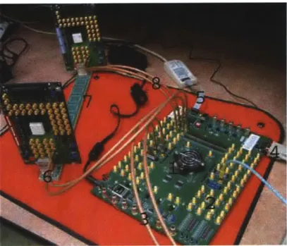
Figure 6: Laboratory Setup. The labels on the figure indicate the 1) Virtex-II Pro X FPGA, 2) RocketIO X SMA Connectors, 3) Differential clock from external signal generator for clocking the transceivers, 4) RS232, 5) JTAG Cable for programming the FPGA, 6) Differential transmit coaxial cables, 7) high-speed backplane, and 8) differential receive coaxial cables.
5
Methodology
5.1
Description of Hardware
The hardware required for the project includes a Xilinx FPGA with built-in transceivers, Rambus line cards and backplanes, coaxial cables, and other general laboratory equipment. The entire set up is shown in Figure 6. A pseudo-random data stream is generated in the FPGA, encoded, sent through the backplane and brought back to the FPGA via the coaxial cables and line cards. Once the FPGA receives the transmitted data, it can be decoded and any errors that occurred may be observed and recorded.
5.1.1 Virtex II-Pro X FPGA
The FPGA board used in the project is a general purpose demonstration board, called the MK325, designed by HiTech Global. It contains a Virtex II-Pro X FPGA.
This particular FPGA has many built-in features that make it suitable for the demands of the project, including:
" Digital Clock Managers (DCMs): The FPGA has eight digital clock managers that can multiply and divide the frequency and change the phase of an input clock. The DCMs allow the user to simply create a system with multiple clock domains without having to bring in extra off-chip clock sources.
* Block RAMs: The Virtex-II Pro X has 308 block RAMS of 18kbits each, which can be combined to make larger storage devices. These block RAMS are suitable for implementing FIFOs and RAMs, which are not efficiently implemented using logic cells.
" RocketIO X Transceivers: The RocketIO X transceiver is the I/O device that is used to drive the device under test (DUT). The next section is devoted to describing the RocketIO X.
" IBM PowerPC Processor: The FPGA has two embedded 32-bit IBM PowerPC processors. The PowerPC processors uses block RAM for its data and instruction memory. PowerPC programs are programmed in C and then loaded into the block RAM when the FPGA is programmed. The proces-sors may be utilized if a software solution is more appropriate to parts of the design. The PowerPCs may also be effectively used for controlling drivers for FPGA peripherals, such as RocketIO drivers. The processors communicate with its peripherals via two buses, called the Processor Local Bus (PLB) and the On-Chip Peripheral Bus (OBP). The designer must connect the peripheral drivers to one of these buses and define its address space. The drivers can then be accessed and manipulated using a the standard address/bus interface.
5.1.2 RocketIO X Transceivers
The RocketIO X, as is typical for high-speed applications, uses differential lines for transmitting and receiving. The MK325 brings out all four pins for each of the 20 transceivers to SMA connectors for a total of 80 SMA connectors. These connectors provide the interface between the RocketIO I/Os and the channel.
The RocketIO transceivers are designed to operate up to 10 Gb/s, though because of board routing and other issues, the MK325 only guarantees operation up to 6.25 Gb/s on all its the transceivers. The
transceiver used in this project was selected based on testing all 20 transceivers for the lowest bit error rate. The selected transceiver is capable of 10 Gb/s operation for channels of relatively high quality, including the channel that consists of a single coaxial cable.
The RocketIO accepts 40 bits of parallel data and transmits the data serially at 40 times the reference clock. The bits are sent from the least significant bit to the most significant bit. For 10 Gb/s operation, the FPGA logic must be clocked at 250 MHz from an external signal generator.
The RocketIO X communicates with the FPGA fabric through dedicated registers. Other than the 40-bit transmit and receive data registers, there are many other registers that control the various transceiver settings. Many of the features of the RocketlO X are bypassed, such as 8B/10B or 64B/66B encoding, so the full effects of the channel and the coders/decoders can be examined. The RocketlO transmit and receive equalizers, however, are also controlled by registers and must be tuned for each channel and each data rate in order to eliminate excessive dispersion ISI. These more advanced features of the RocketlO X can be manipulated using a special bus, called the Physical Media Attachment (PMA) Attribute Programming Bus.
The RocketIO uses very simple equalizers that have rather coarse resolution. On the transmit side, two separate registers combine to control the output swing and pre-emphasis levels. Between the two registers, there are a total of 72 combinations. Depending on the chosen values, the output swing ranges from 120 mV to 780 mV (single ended) and the pre-emphasis levels ranges from 0% to 500%. On the receiver side, the magnitude of a highpass filter is controlled by a 10-bit register, where two bits control the filter value between 50 MHz and 200 MHz, two bits control between 200 and 500 MHz, and six bits control between 500 MHz and 2 GHz. For more information on the RocketIO X, refer to [17].
5.2
Desired Information to Capture
The purpose of the hardware system is to obtain enough information to get a reasonably clear picture of how the channel noise affects the link. Other than obtaining the bit error rate, there is a wide range of valuable information that can be captured about the error distribution. The type of errors caused by channel noise directly determines what kind of code will be most effect at correcting or detecting them.
Figure 7: Different Materials Used in Backplanes. From front to back, the picture shows a Rogers, NELCO, and FR4 link.
The error distribution affects three crucial aspects of a code: the expected Hamming distance required by a code, the expected burst length correction/detection capability, and the range of block sizes, n, that can be considered.
The expected number of errors in the block increases as the block size increases, but the code rate in-creases as well. Thus, there is always a tradeoff between the block size and the needed detecting/correcting capability of a code. It is this tradeoff that the designed system must be able to evaluate. Even though the hardware imposes some restrictions on the block size, it is necessary that system be able to handle a range of block sizes. For each block size, obtaining the distribution of both the burst length of errors and the number of errors in the block completes the picture.
5.3
Line Cards and Backplanes
The line card used in the project is pictured in the top left corner of Figure 6. Typically, data is generated on the white chip in the middle of the line card, as is diagrammed in Figure 1. However, in this case the data is brought in externally using coaxial cables, also pictured, from the Virtex-I Pro X FPGA.
There are multiple types of backplanes available for the project, each of which are 20 inches long. Figure 7 pictures backplanes with different substrates. The figure shows, from front to back, a Rogers, NELCO, and FR4 backplane. FR4 is the typical material used for circuit boards. However, FR4 may be too lossy at the high bandwidths required of high-speed links. NELCO and Rogers are alternatives to FR4 and provide lower loss solutions.
There are many sources of reflections due to discontinuities in the signal path. One way of reducing reflections between the line card and the backplane is to drill out the vias connecting them, a technique
Code Select Code Enable
Generator EnAT
oder
Rocket1O X
Transceiver To Link
Code Select Decoder RXDATA sesd
Code Enal G enerato r
Error Ve ctor
Clect ChanneI
Error Statistic s
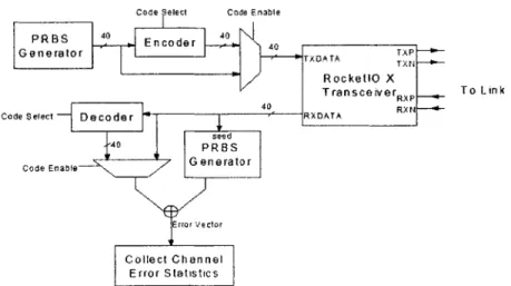
Figure 8: High Level Block Diagram
called counterboring. The backplanes used in the project do not utilize counterboring, since they are the more interesting case. Thus, due to availability, the choices are limited to NELCO and Rogers. Of the two, the Rogers link is chosen for study, because it results in more errors and is therefore more interesting.
5.4
High Level Description of the Design
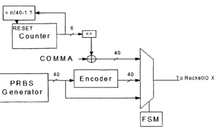
In its simplest form, the system can be viewed as the diagram in Figure 8.
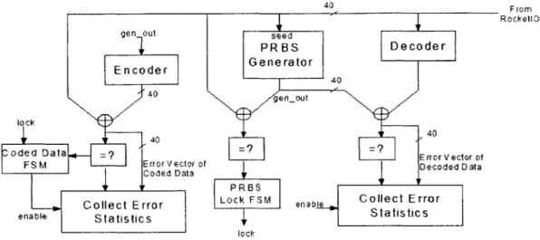
At one end, the transmitter generates a pseudo-random bit sequence (PRBS) in blocks of 40, codes the sequence, and sends it through the channel. The receiver then uses the transmitted data to seed a replica of the transmitter's pseudo-random number generator. As long as the seed value is error-free, the receiver's PRBS generator can produce the same sequence as the transmitter's. When the receiver can accurately predict the incoming data, a locked state has been achieved. Once locked, the receiver need only compare the incoming data to the generated data to determine whether any errors have occurred.
If there are errors, then the error vector is saved for processing. In the processing stage, both the error
length and the number of errors are calculated, as required by the discussion in the previous section. In the next subsections, each portion of the design is discussed more thoroughly. The transmitter and receiver design is based loosely on the Xilinx RocketIO Bit Error Rate Tester application note [18].
![Figure 1: High-Speed Link Channel Diagram [1]](https://thumb-eu.123doks.com/thumbv2/123doknet/14229049.485227/8.918.197.705.824.983/figure-high-speed-link-channel-diagram.webp)