Author(s) - Auteur(s) :
Publication date - Date de publication :
Permanent link - Permalien :
Rights / License - Licence de droit d’auteur :
Engineering 3D bicontinuous hierarchically macro-mesoporous LiFePO4/C
nanocomposite for lithium storage with high rate capability and long cycle stability
Zhang, Qian; Huang, Shao Zhuan; Jin, Jun; Liu, Jing; Li, Yu; Wang, Hong En; Chen, Li Hua;
Wang, Bin Jie; Su, Bao Lian
Published in:
Scientific Reports
DOI:
10.1038/srep25942
Publication date:
2016
Document Version
Publisher's PDF, also known as Version of record
Link to publication
Citation for pulished version (HARVARD):
Zhang, Q, Huang, SZ, Jin, J, Liu, J, Li, Y, Wang, HE, Chen, LH, Wang, BJ & Su, BL 2016, 'Engineering 3D
bicontinuous hierarchically macro-mesoporous LiFePO4/C nanocomposite for lithium storage with high rate
capability and long cycle stability', Scientific Reports, vol. 6, 25942. https://doi.org/10.1038/srep25942
General rights
Copyright and moral rights for the publications made accessible in the public portal are retained by the authors and/or other copyright owners and it is a condition of accessing publications that users recognise and abide by the legal requirements associated with these rights. • Users may download and print one copy of any publication from the public portal for the purpose of private study or research. • You may not further distribute the material or use it for any profit-making activity or commercial gain
• You may freely distribute the URL identifying the publication in the public portal ?
Take down policy
If you believe that this document breaches copyright please contact us providing details, and we will remove access to the work immediately and investigate your claim.
www.nature.com/scientificreports
Engineering 3D bicontinuous
hierarchically macro-mesoporous
LiFePO
4
/C nanocomposite for
lithium storage with high rate
capability and long cycle stability
Qian Zhang
1, Shao-Zhuan Huang
1, Jun Jin
1, Jing Liu
1, Yu Li
1, Hong-En Wang
1, Li-Hua Chen
1,
Bin-Jie Wang
2& Bao-Lian Su
1,3,4A highly crystalline three dimensional (3D) bicontinuous hierarchically macro-mesoporous LiFePO4/C
nanocomposite constructed by nanoparticles in the range of 50~100 nm via a rapid microwave assisted solvothermal process followed by carbon coating have been synthesized as cathode material for high performance lithium-ion batteries. The abundant 3D macropores allow better penetration of electrolyte to promote Li+ diffusion, the mesopores provide more electrochemical reaction sites and the carbon
layers outside LiFePO4 nanoparticles increase the electrical conductivity, thus ultimately facilitating
reverse reaction of Fe3+ to Fe2+ and alleviating electrode polarization. In addition, the particle size in
nanoscale can provide short diffusion lengths for the Li+ intercalation-deintercalation. As a result, the
3D macro-mesoporous nanosized LiFePO4/C electrode exhibits excellent rate capability (129.1 mA h/g
at 2 C; 110.9 mA h/g at 10 C) and cycling stability (87.2% capacity retention at 2 C after 1000 cycles, 76.3% at 5 C after 500 cycles and 87.8% at 10 C after 500 cycles, respectively), which are much better than many reported LiFePO4/C structures. Our demonstration here offers the opportunity to develop
nanoscaled hierarchically porous LiFePO4/C structures for high performance lithium-ion batteries
through microwave assisted solvothermal method.
Lithium-ion batteries (LIBs) have been rapidly developed for applications in plug-in hybrid electric vehicles (HEVs), electric vehicles (EVs) and large-scale energy storage due to their high energy density and durable cycle life1–6. In general, the performance of LIBs is determined by the electrode materials. From the viewpoint of
elec-trode materials, the olivine-type LiFePO4 is considered as one of the most promising cathode materials owing to
its high operating voltage (~3.4 V vs Li/Li+), high theoretical capacity (~170 mA h/g), low cost and
environmen-tally benign7,8. In fact, LiFePO
4 has been successfully used for HEVs and EVs. The low intrinsic electronic9 and
ionic conductivity10 of LiFePO
4, however, limit its widespread applications. Such poor electronic conductivity is
caused by the lack of mixed valence due to the low solubility of LiFePO4 and FePO4 and the highly localized Fe2+
or Fe3+ ions, while the poor Li+ conductivity is caused by one-dimensional diffusion of Li+ to form edge-shared
LiO6 octahedron along b-axis11. Thus, seeking approaches to improve its electrochemical performance is still
highly pursued by materials scientists.
At present, huge efforts have been made to address the above problems, including reducing the particle size12–14
to shorten the ionic and electrical path length, and coating carbon or other conducting layers15–17 to enhance the
electrical conductivity. Combination of nanostructure with carbon coating is a widely adopted route to effec-tively resolve the aforementioned low intrinsic electronic and ionic conductivity problem18–20. According to the 1Laboratory of Living Materials at the State Key Laboratory of Advanced Technology for Materials Synthesis and
Processing, Wuhan University of Technology, 122 Luoshi Road, 430070, Wuhan, Hubei, China. 2FEI company,
Shanghai Nanoport, 399 Shenxia Road, 201210 Shanghai, China. 3Laboratory of Inorganic Materials Chemistry
(CMI), University of Namur, 61 rue de Bruxelles, B-5000 Namur, Belgium. 4Department of Chemistry and Clare Hall,
University of Cambridge, Cambridge, CB2 1EW, United Kingdom. Correspondence and requests for materials should be addressed to Y. L. ([email protected]) or B.L.S. ([email protected])
Received: 26 February 2016 Accepted: 25 April 2016 Published: 16 May 2016
characteristic time constant t for diffusion being proportional to the square of diffusion length L (t ≈ L2/D)21, one
can see that reducing the characteristic dimensions of electrolytically active materials is more effective to improve battery cycling rates than increasing the ion diffusivity D. However, due to the inadequate contact between the electrodes and electrolytes, single structured nanomaterials such as nanoparticles22, nanorods23, nanowires24 are
difficult, to some extent to obtain the highly efficient ion and electron pathways. Recently, our group found that hierarchically nanostructured porous materials, benefiting from large surface areas for reaction, interfacial trans-port, or dispersion of active sites at different length scales of pores and shortened diffusion paths or reduced diffusion effect, can largely improve their electrochemical properties25–30. Preparation of hierarchically porous
LiFePO4 nanostructures is thus a promising route to improve their electrochemical properties, such as capacities,
rate performances and cycle life.
Among the various synthesis methods18,31–34, hydrothermal methods have been particularly successful in
offering high performance LiFePO4 nanostructures35–37. But long reaction time is often required. In our previous
work, we found that the microwave assisted hydrothermal method can quickly enhance the crystallization of nanoparticles constructed mesoporous TiO2 microspheres for high performance LIBs38. This means microwave
assisted hydrothermal synthesis may not only improve the crystallization of the target materials but also short the reaction time. In fact, microwave assisted hydrothermal synthesis has been adopted to rapidly synthesize prod-ucts with highly controllable particle size and morphology39,40. However, to the best of our knowledge, synthesis
of hierarchically porous LiFePO4 nanostructures via microwave assisted solvothermal method has never been
reported.
Herein, we report the synthesis of highly crystalline 3D bicontinuous hierarchically macro-mesoporous LiFePO4/C (LFP/C) nanocomposite as cathode material for LIBs. We first synthesize the LiFePO4
precur-sor (LFP-P) via a rapid microwave assisted solvothermal process in 1 h. To increase the conductivity of the as-prepared LFP-P, sucrose is then used as carbon source to coat carbon layer on the surface. After calcination at 700 °C, the highly crystalline 3D hierarchically macro-mesoporous LFP/C nanocomposite is obtained. The as-synthesized LiFePO4/C cathode exhibits low polarization, enhanced electrical conductivity, excellent rate
capa-bility and long cycling life for LIBs.
Results
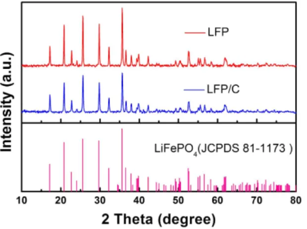
X-ray diffraction (XRD) patterns of the as-synthesized LFP and LFP/C materials are shown in Fig. 1. The entire diffractions of the two samples match well with the standard orthorhombic LiFePO4 (JCPDS: 81–1173). The
strong and sharp peaks suggest good crystallinity for two samples, which is quite different from the XRD patterns of LFP-P (Figure S1). It is noticeable that the peaks of LFP/C are wider than that of LFP, indicating smaller nano-particles in LFP/C compared with LFP. No impurities such as Li3PO4 can be observed, suggesting that our method
is favorable for pure LiFePO4 preparation. No typical diffraction peaks of carbon are found in LFP/C sample,
indicating the carbon in amorphous form.
The morphologies of the as-synthesized LFP-P, LFP and LFP/C samples are observed by scanning electron microscopy (SEM). Figure S2 illustrates the morphology of LFP-P, which gives a 3D bicontinuous macroporous structure constructed by nanoparticles of ~30 nm. Noticeably, after calcination, the macroporous structure is well retained as shown in Fig. 2a. However, the nanoparticles of LFP grow to ~300 nm (Fig. 2b). After carbon coating, the 3D hierarchically macroporous structure is still maintained (Fig. 2c). Figures S3–S5 present more SEM images to show the hierarchically porous structure among the whole structure. Figure 2d also shows that the nanopar-ticles are jointed each other to maintain 3D bicontinuous hierarchically macro-mesoporous structure instead of aggregation together. It is noted that after carbon coating, the nanoparticles of LFP/C can keep their small size at 50~100 nm. This means that the carbon coating can effectively prevent the quick growth of LiFePO4
nanoparti-cles, which is quite important to shorten the ionic and electrical path lengths for LIBs.
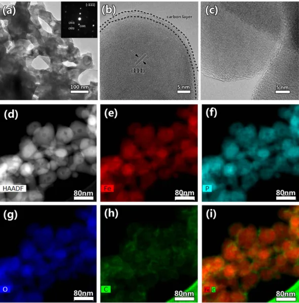
The TEM characterizations are employed to reveal more detail structure information of LFP and LFP/C. Figure S6 presents the TEM and HRTEM images of LFP. It clearly shows the bicontinuous macroporous structure constructed by nanoparticles and no amorphous layer can be found at the surface of the particle. Figure 3a dis-plays the typical TEM image of LFP/C, indicating the macro-mesoporous structure. This is consistent with SEM
www.nature.com/scientificreports/
observation. It is noted that there are also many pores inside the nanoparticles (Fig. 3a and Figure S7). This is also clearly displayed in HAADF image (Fig. 3d). Such 3D bicontinuous macro-mesoporous structure constructed by highly crystalline LFP nanoparticles is very helpful for LIBs, which can facilitate the electrolyte permeation and the smaller nanoparticles can provide short diffusion lengths for Li+ in the intercalation-deintercalation process.
The inserted SAED pattern in Fig. 3a is recorded from one nanoparticle. The sharp diffraction spots indicate the nanoparticles are single crystals. This is also useful for electrons and ions diffusion in the crystal structure. The HRTEM in Fig. 3b demonstrates that the lattice fringes correspond to the (111) crystal plane of olivine-type LiFePO4. A uniform carbon layer at ~3 nm on the LiFePO4 crystal surface can be clearly observed. This thin and
uniform coated carbon layer can smooth electron migration for the reverse reaction of Fe3+ to Fe2+. Figure 3c
displays the interface of two nanoparticles. It clearly shows that there is no obvious interface between two nano-particles, verifying that the nanoparticles are interconnected each other. This verifies that the nanoparticles are jointed each other to form 3D bicontinuous hierarchically macro-mesoporous structure. To clearly reveal the element distribution in LFP/C, STEM-EDS technique is employed as shown in Fig. 3d–i. The element mapping images from Fig. 3e–g show the homogeneous distribution of Fe, P and O elements among the whole product. In particular, Fig. 3h displays the carbon layer in LFP/C, demonstrating the hollow structure of carbon. After the super imposition of images about Fe and C together, Fig. 3i obviously shows that the carbon is at the shell of LiFePO4 nanoparticles, verifying C uniformly coated on the surface of LiFePO4 nanoparticles.
The growth process of such 3D bicontinuous macro-mesoporous structure is monitored and schemed in Fig. 4. We can see that when the reaction time is 5 minutes, the products are small nanoparticles with size of ~10 nm. After 10 minutes, the nanoparticles further grow and begin to assemble to form a 3D bicontinuous macro-mesoporous structure. And the following 50 minutes is just the crystallites further growth and crystalli-zation, ultimately to form LFP-P. After sucrose is added accompanying with the subsequent calcination, the nan-oparticles are coated with a carbon layer and the 3D bicontinuous hierarchically macro-mesoporous LiFePO4/C
nanocomposite is formed.
Raman characterization is performed to probe the vibrational modes of both crystalline and amorphous mate-rials in LFP and LFP/C (Fig. 5a). The Raman spectrum of LFP/C displays two broad peaks at 1320 and 1609 cm−1,
corresponding to the D band (disordered carbon, sp3) and G band (graphite, sp2) of Raman vibration modes for
amorphous carbon, respectively41–45. The D band and G band are also been observed for LFP, indicating carbon
existence although it is not observed by TEM. This should be originated from the carbonization of the absorbed DEG molecules on LFP-P, resulting in very thin carbon layer or randomly distributed carbon in LFP. It is interest-ing to see that the ID/IG ratio (0.92) of LFP is a little lower than that of LFP/C (1.02), indicating less carbon source
is more suitable for organic molecules carbonization. However, too low carbon content is not helpful for particle size control according to our SEM and TEM observations. Other peaks should be attributed to the orthorhombic LiFePO4. Particularly, two peaks at 947 cm−1 and 586 cm−1 for both samples are assigned to the intra molecular
stretching modes (ν 1, ν 4) of the PO43− anion43. The Raman behaviors are very well consistent with those already
reported LiFePO4/C composites18,46,47. It is noted that the signals of LFP/C are higher than those of LFP. This
should be close related to the better crystal structure features of LFP/C comparing to LFP, which is very important for electrons and ions diffusion in the structure leading to better electrochemical performance of LFP/C.
TG/DSC measurement of LFP and LFP/C is conducted to estimate the carbon content (Fig. 5b). For LFP, a weight gain around 5.21 wt% at 250–500 °C corresponds to the oxidation of LiFePO4 to Li3Fe2(PO4)3 and Fe2O331.
For LFP/C, the weight gain is only 2.44 wt%, due to the oxidation of carbon in the composite (an apparent exo-thermic peak around 325 °C), leading to a slight decrease of weight gain. Then the carbon content is 2.77 wt% for LFP/C. Above the temperature of 600 °C, a total oxidization of both LiFePO4 and carbon is completed.
The nitrogen adsorption-desorption isotherm of LFP/C exhibits a type-II shape (Fig. 5c), indicating the pres-ence of macropores26. LFP/C exhibits a BET specific surface area of 20.0 m2/g, much higher than that of LFP
(0.1 m2/g). This high BET surface area is favorable for enhanced contacting with the liquid electrolyte. Moreover,
the pore size distribution (Fig. 5c inset) gives pore size centered at ~4 nm. The presence of 3D hierarchical macro-mesoporosity is beneficial for electrolyte ions diffusion and transport through the LFP/C composite.
Figure 6a presents the cyclic voltammograms (CV) curves of the LFP/C and LFP electrodes at a scan rate of 0.2 mV/s within the potential window of 2–4 V (vs. Li/Li+). For the LFP/C electrode, the anodic peak at 3.58 V
corresponds to the oxidation of Fe2+ to Fe3+, while the cathodic one appearing at 3.31 V is associated with the
reduction of Fe3+ to Fe2+ 48. The potential interval between the two redox peaks is 0.27 V. The narrow peak
sepa-ration means a low polarization of the electrodes, indicating the easily electrochemical reverse reaction of Fe3+
to Fe2+ during the Li+ insertion-desertion process. As for the LFP electrode, the potential interval between the
two redox peaks is 0.41 V, much larger than that of LFP/C. This can lead to a restricted electrochemical reverse reaction from Fe3+ to Fe2+ during the Li+ insertion-desertion process. This phenomenon means that the carbon
layer can improve the electronical conductivity of the LFP/C electrode, resulting in a decreased polarization of
Figure 3. (a) TEM image, (b,c) HRTEM images and (d–i) STEM-EDS elemental mapping images of LFP/C.
www.nature.com/scientificreports/
the electrode. In addition, the peak profiles of LFP/C are narrower with a high peak current, indicating a lower conductivity restriction and diffusion limitation comparing to LFP. These results highlight the improvements of LFP/C for high performance of LIBs that come from the 3D bicontinuous macro-mesoporous structure, the small particle size and uniformly coated carbon layer.
Figure 6b shows the CV results of LFP/C electrode at various scanning rates from 0.1–2.0 mV/s after a scan rate of 0.2 mV/s for three cycles. The symmetry of the sharp oxidation and reduction peaks confirms the good reversibility of lithium extraction-insertion reactions in LFP/C. Two redox peaks are observed between 3.3 V and 3.6 V (vs. Li/Li+) at a scan rate of 0.1 mV/s. These well-defined peaks correspond to the insertion and de-insertion
of Li+ in the LiFePO
4 nanoparticles and are still clearly visible at higher scanning rates with wider separation
of peak positions. The peak currents Ip (Amperes) at different sweep rates can be used to evaluate Li+ diffusion
coefficient D (cm2/s), according to the Randles Sevcik equation49: I
p = 2.69 × 10⁵ A C D1/2 n3/2 v1/2, where A is the
electrode area (cm2), C is the concentration of the species being oxidized or reduced (mol/cm3), n is the number
of electrons transferred (n = 1 for Fe2+/Fe3+ redox pair), and v is the potential scan rate (V/s). The peak current is
in linear response to the square root of scanning rate (ν ) as shown in Fig. 6c. The average Li+ diffusion coefficients
of the LFP/C composite are estimated to be ~7.0 × 10⁻¹⁴ cm2 s−1 and ~4.0 × 10⁻¹⁴ cm2 s−1 for the charge and
dis-charge processes respectively which are as good as the nano-sized LiFePO4 material reported before50.
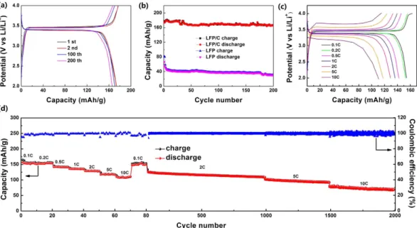
The typical charge and discharge profiles of the LFP/C electrode at a current rate of 0.2 C are shown in Fig. 7a. The LFP/C electrode exhibits the high first charge and discharge capacities of 177.1 and 173.8 mA h/g respectively, with an initial coulombic efficiency of 98%, and the second cycle curves match well with the initial ones, and after 100 and 200 cycles, the capacity retention is 98.3% and 95.6% respectively, indicating the excellent cyclic stability. The coated carbon layer and the small particle size increase the electrical and ionic conductivity and further enhance the kinetic reaction, facilitating more Fe2+ oxidation to Fe3+ as suggested by CV results, leading
to higher capacity than LFP. It is noticeable that the profiles of LFP/C are long and flat, and the gap between the charge and discharge curves of LFP/C is small, indicating the fast redox reaction and phase transition in LFP/C. Such excellent performance of LFP/C is attributed to the 3D bicontinuous macro-mesoporous structure, small particle size and coated carbon layer, which ensure the short transport of Li+ without excessive polarization and
improved electrical and ionic conductivity.
Figure 7b presents the cycle performance of the LFP/C and LFP electrodes at 0.2 C. The initial discharge capacity of LFP/C and LFP is 173.8 and 66.6 mA h/g, and after 200 cycles, the capacity retention is 95.6% and 45.6%, respectively. The results demonstrate the excellent cycling stability of the 3D macro-mesoporous LFP/C nanocomposite.
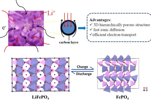
Figure 7c shows the charge-discharge curves at various discharge rates from 0.1 C to 10 C of LFP/C. The flat voltage plateaus around 3.4 V imply the two-phase LiFePO4 ↔ FePO4 + Li+ + e− reaction7. The voltage differences
between the charge and discharge curves at 0.1, 1, 5 and 10 C (measured at the half capacities of these curves) are ~63, 104, 294.5 and 518 mV, respectively. The slight voltage differences indicate the good electronic conductivity of the LFP/C nanocomposite, resulting in the better redox reactions in LFP/C during the Li+ insertion-desertion
process. This is in agreement with the CV results.
Figure 7d gives the rate performance of the LFP/C electrode. As can be seen, the capacity values drop with the increase of charge-discharge rates, being associated with the sluggish Li+ diffusion kinetics at very high rates.
As for LFP/C, a high discharge capacity of 156.9 mA h/g is achieved at a low rate of 0.1 C. A discharge capacity of 129.1 mA h/g can be obtained at 2 C. The capacity can still be maintained at 110.9 mA h/g after the rate increases to 10 C. When the current density returns back to 0.1 C, the discharge capacity recovers to 152.9 mA h/g, demon-strating the high rate performance and stability of LFP/C. The long-cycle rate performance of the LFP/C electrode
Figure 4. Schematic illustration for the preparation of LFP/C. The embedded SEM images are the products
is further employed at the same unit cell. It presents that even at the high rate of 5 C and 10 C, the LFP/C can still keep high and steady capacity. The capacity retention is 87.2% at 2 C (1000 cycles), 76.3% at 5 C (500 cycles) and 87.8% at 10 C (500 cycles). After 2000 cycles at different rates, the discharge capacity can still maintain at 80 mA h/g. The Coulombic efficiency is always ~100% during the whole process.
The rate performance of our LFP/C composite is much better than nanostructured LiFePO4/C20, hierarchically
dumbbell-like LiFePO4 microstructures51, LiFePO4 microstructures52 and rugby-like LFP/C/RGO53, almost the
same with monodisperse hollow LiFePO4 microspheres54 and hierarchically structured LiFePO455. This result
indicates that our LFP/C composite exhibits a competitive rate performance than most of the previous results, owing to the 3D bicontinuous hierarchically macro-mesoporous structure, the small particle size and coated carbon layer. Therefore, it can be regarded that the 3D bicontinuous hierarchically macro-mesoporous LFP/C composite developed in this work provides a high rate capability.
The electrochemical impedance spectroscopy (EIS) of the LFP and LFP/C electrodes is performed to fur-ther investigate their electrochemical kinetics (Fig. 8). The kinetic differences of LFP/C electrode after 10 cycles (LFP/C-10), after 20 cycles (LFP/C-20) and LFP electrode after 10 cycles (LFP-10) are investigated by modeling AC impedance spectra based on the modified equivalent circuit. In the equivalent circuit, Re is the total resistance
of electrolyte, electrode and separator. CPE1 and Rct are the double layer capacitance and charge transfer
resist-ance, respectively. CPE2 and Rf are the capacitance and resistance of the surface film formed on the electrode,
respectively. Zw is the Warburg impedance related to the diffusion of lithium ions into the bulk electrode. The
Figure 5. (a) Raman spectra of LFP and LFP/C, (b) TG-DSC curves of the LFP and LFP/C recorded from the
room temperature to 900 °C at a heating rate of 10 °C min−1 in air, (c) Nitrogen adsorption-desorption isotherm
www.nature.com/scientificreports/
fitting values from this equivalent circuit are presented in Table 1. It clearly shows that the diameter of semicircle for the LFP/C electrode in the high medium frequency region is much smaller than that of the LFP electrode, suggesting that the LFP/C electrode possesses a lower charge transfer resistance. The value of the diameter of the semicircle on the real axis is approximately equal to Rct. The Rct value of the LFP/C-10 electrode (108.6 Ω)
is slightly lower than that of the LFP/C-20 electrode (131.3 Ω), which is related to the slight polarization during cycling process, but much lower than that of the LFP-10 electrode (1476.2 Ω). These results confirm that the carbon coating endows the LiFePO4 electrode with a high conductivity and largely enhanced electron transport
during the electrochemical lithium insertion/extraction reaction.
To further understand the electrochemical performance and structural stability of the LFP/C cathode mate-rial, postmortem studies after 2000 charge-discharge cycles at different rates are carried out through SEM and TEM observations. For the post-mortem studies, the LFP/C cathode material after 2000 cycles is removed from the unit and immersed in acetone for one week to wash off the electrolyte. SEM (Fig. 9a,b) and TEM (Fig. 9c) images display that the 3D macroporous architecture is maintained after the electrochemical reaction, indicating the structural and electrochemical stability of LFP/C. This leads to the excellent capacity retention and superior rate performance. The HRTEM in Fig. 9d still shows the ~3 nm carbon layer on the LiFePO4 crystal surface. The
lattice spacing of the particle is measured to be 3.64 Å, corresponding to the (011) crystal plane of LiFePO4. This
Figure 6. (a) CV curves of LFP and LFP/C electrodes at a scan rate of 0.2 mV/s, (b) CV curves of the LFP/C
electrode at scan rates of 0.1~2 mV/s, (c) linear response of the peak current (Ip) as a function of the square root
result shows that the 3D bicontinuous hierarchically macro-mesoporous structure is retained well after the long electrochemical reaction at different high rates.
According to the above results and discussion, the attractive high performance of LFP/C is achieved. This can be ascribed to a mixed conducting network with 3D bicontinuous hierarchical macro-mesopores serving as the ionic conducting network, the carbon coating on the surface of LiFePO4 crystals serving as the electronic
Figure 7. (a) Charge and discharge profiles of LFP/C between 2.0 and 4.0 V at 0.2 C for the first, second, 100th
and 200th cycles. (b) Cycle performance of LFP and LFP/C at 0.2 C. (c) Charge and discharge profiles of LFP/C in the potential region from 2.0 to 4.0 V at various rates. (d) The long-cycle rate performances of LFP/C.
Figure 8. The equivalent circuit and Nyquist plots of the LFP and LFP/C electrodes. Frequency range:
10 mHz–100 kHz.
Samples Re (Ω) Rct (Ω) Rf (Ω) CPE1 (F) CPE2 (F)
LFP-10 3.8 1476.2 0.4 4.4 × 10⁻⁵ 3.3 × 10⁻¹⁴
LFP/C-10 3.5 108.6 95.6 7.9 × 10⁻⁶ 1.5 × 10⁻³
LFP/C-20 3.3 131.3 174.8 9.4 × 10⁻⁶ 1.1 × 10⁻³
www.nature.com/scientificreports/
conducting network, and the small nanoparticles providing short diffusion lengths for Li+ insertion-deinsertion
as schemed in Fig. 10. The synergy of the above mentioned features leads to this 3D macro-mesoporous architec-ture of LFP/C being of the promising electrode material for high-power and high-energy lithium ion batteries.
Discussion
Highly crystalline 3D bicontinuous macro-mesoporous LFP/C nanocomposite has been synthesized via a rapid microwave assisted solvothermal process and subsequent carbon coating. The as-synthesized LFP/C composite exhibits excellent electrochemical performance, especially for high rate performance. This can be ascribed to sev-eral factors, such as the 3D bincontinuous macro-mesoporous structure, the fast ionic diffusion in the crystalline nano-sized LiFePO4 as well as the efficient electron transport that benefits from the intimate contact between
LiFePO4 nanoparticles and conductive carbon layer, all of which endow the high performance of LiFePO4. This
work makes us believe that if we can ensure the in-situ carbonization to get the carbon layer with appropriate thickness (2~3 nm), this structure can bring even much better performance for LIBs.
Methods
Synthesis of LFP-P.
In a typical synthesis, 0.01 mol Fe(NO3)3• 9H2O and 0.01 mol CH3COOLi• 2H2O areadded into 70 mL diethylene glycol (DEG). After vigorously magnetic stirring for 0.5 h, a red wine-colored transparent solution is formed. Then 0.01 mol H3PO4 (85 wt% solution) is added into the above solution, and
it changes to yellow instantly. After vigorously magnetic stirring for 0.5 h, the reaction solution is transferred into a 100 mL Teflon vessel, sealed, and heated at 220 °C for 1 h in a commercial microwave reaction apparatus (MDS-8G, Shanghai Sineo Microwave Chemistry Technology Co. Ltd.). After cooling down to room temperature, the obtained grey dark slurry is centrifuged, washed several times with absolute alcohol and distilled water, and finally dried at 60 °C for 12 h to get LiFePO4-precursor (LFP-P).
Synthesis of LFP/C and LFP.
The LFP/C composite is obtained by mixing LFP-P powder and sucrose (the weight ratio of LFP-P: Carbon = 1: 0.04) in 4 mL distilled water and 6 mL absolute alcohol. The mixture is stirred at 80 °C until the distilled water and absolute alcohol completely evaporated, and then dried at 60 °C for 12 h. The mixture is grinded and annealed at 700 °C under Ar/H2 (95:5) atmosphere for 10 h with a heating rate of 3 °Cmin−1. To obtain LiFePO
4 (LFP), the LFP-P is directly annealed following the procedure described for LFP/C.
Materials characterization.
X-ray diffraction (XRD) patterns are obtained by a Bruker diffractometer at 40 kV, 40 mA, with Cu Kα radiation (λ = 1.54056 Å). The morphology of all the products is performed on scanning electron microscopy (SEM, Hitachi S-4800) equipped with a field-emission gun at an accelerated voltage at 5 kV.Figure 9. Post-mortem studies of the LFP/C cathode material after 2000 charge-discharge cycles at different rates. (a,b) SEM images, (c) TEM image and (d) HRTEM image.
Transmission electron microscopy (TEM), high resolution transmission electron microscopy (HRTEM), scanning transmission electron microscopy (STEM) and energy-dispersive X-ray spectroscopy (EDS) are acquired on an FEI Talos F200X with an acceleration voltage of 200 kV. Thermogravimetric analysis (TGA) is performed using a Labsys Evo S60/58458 thermal analysis instrument at a temperature ramping rate of 5 °C min−1 in air atmosphere. Raman
spectra are carried out at room temperature on an Invia Raman Microscope (Invia Microscope, Renishaw, UK) with 514.5 nm laser radiation at a laser power of 0.48 mW in the range of 200–2000 cm−1. Nitrogen adsorption–
desorption isotherms were obtained using a Tri Star surface area & porosity analyzer (Tri Star II 3020) at 77 K. The specific surface area was calculated by the Brunauer–Emmett–Teller (BET) method. The pore size distribu-tion was calculated by the Barrett–Joyner–Halenda (BJH) method.
Electrochemical measurements.
The working electrodes are fabricated by using LFP (or LFP/C) as the active materials, conductive carbon blacks (Super-P) and polyvinylidene fluoride (PVDF) binder in a weight ratio of 70:20:10. The slurry is coated on aluminum foil and dried in vacuum at 120 °C for 12 h. Electrochemical measurements are carried out via CR2025 coin type cell using lithium pellets as the counter electrode and the reference electrode, a 1 M solution of LiPF6 in ethylene carbon (EC)/dimethyl carbonate (DMC) (1:1 w/w) aselec-trolyte. The cells are assembled in an argon-filled glove-box. Cyclic Voltammetry (CV) measurements are carried out using a CHI 660D electrochemical workstation at a scanning rate of 0.1–2 mV s−1. Galvanostatic charge/
discharge cycling is studied in a potential range of 2 V–4 V vs Li/Li+ with a multichannel battery testing system
(LAND CT2001A). Electrochemical impedance spectra (EIS) are measured with an electrochemical workstation (Autolab PGSTAT 302N) in the frequency range from 100 KHz to 10 mHz.
References
1. Gogotsi, Y. & Simon, P. True performance metrics in electrochemical energy storage. Science 334, 917–918 (2011). 2. Kang, B. & Ceder, G. Battery materials for ultrafast charging and discharging. Nature 458, 190–193 (2009).
3. Dunn, B., Kamath, H. & Tarascon, J. M. Electrical energy storage for the grid: a battery of choices. Science 334, 928–935 (2011). 4. Goodenough, J. B. & Park, K. S. The Li-ion rechargeable battery: a perspective. J. Am. Chem. Soc. 135, 1167–1176 (2013). 5. Chan, C. K. et al. High-performance lithium battery anodes using silicon nanowires. Nat. Nanotechnol. 3, 31–35 (2008).
6. Bruce, P. G., Scrosati, B. & Tarascon, J. M. Nanomaterials for rechargeable lithium batteries. Angew. Chem. Int. Ed. 47, 2930–2946 (2008).
7. Padhi, A. K., Nanjundaswamy, K. & Goodenough, J. Phospho‐olivines as positive‐electrode materials for rechargeable lithium batteries. J. Electrochem. Soc. 144, 1188–1194 (1997).
8. Shen, L., Li, H., Uchaker, E., Zhang, X. & Cao, G. General strategy for designing core–shell nanostructured materials for high-power lithium ion batteries. Nano Lett. 12, 5673–5678 (2012).
9. Chung, S. Y., Bloking, J. T. & Chiang, Y. M. Electronically conductive phospho-olivines as lithium storage electrodes. Nat. Mater. 1, 123–128 (2002).
10. Prosini, P. P., Lisi, M., Zane, D. & Pasquali, M. Determination of the chemical diffusion coefficient of lithium in LiFePO4. Solid State Ionics 148, 45–51 (2002).
11. Bi, Z., Zhang, X., He, W., Min, D. & Zhang, W. Recent advances in LiFePO4 nanoparticles with different morphology for
high-performance lithium-ion batteries. RSC Adv. 3, 19744–19751 (2013).
12. Dokko, K., Koizumi, S., Nakano, H. & Kanamura, K. Particle morphology, crystal orientation, and electrochemical reactivity of LiFePO4 synthesized by the hydrothermal method at 443 K. J. Mater. Chem. 17, 4803–4810 (2007).
www.nature.com/scientificreports/
13. Oh, S. W. et al. Double carbon coating of LiFePO4 as high rate electrode for rechargeable lithium batteries. Adv. Mater. 22, 4842–4845
(2010).
14. Wang, J. & Sun, X. Understanding and recent development of carbon coating on LiFePO4 cathode materials for lithium-ion batteries. Energ. Environ. Sci. 5, 5163–5185 (2012).
15. Murugan, A. V., Muraliganth, T. & Manthiram, A. One-pot microwave-hydrothermal synthesis and characterization of carbon-coated LiMPO4 (M = Mn, Fe, and Co) cathodes. J. Electrochem. Soc. 156, A79–A83 (2009).
16. Dominko, R. et al. The role of carbon black distribution in cathodes for Li ion batteries. J. Power Sources 119, 770–773 (2003). 17. Song, G. M., Wu, Y., Xu, Q. & Liu, G. Enhanced electrochemical properties of LiFePO4 cathode for Li-ion batteries with amorphous
NiP coating. J. Power Sources 195, 3913–3917 (2010).
18. Zhou, N. et al. Additive-free solvothermal synthesis of hierarchical flower-like LiFePO4/C mesocrystal and its electrochemical
performance. RSC Adv. 3, 19366–19374 (2013).
19. Ni, H., Liu, J. & Fan, L. Z. Carbon-coated LiFePO4–porous carbon composites as cathode materials for lithium ion batteries. Nanoscale 5, 2164–2168 (2013).
20. Di Lupo, F., Meligrana, G., Gerbaldi, C., Bodoardo, S. & Penazzi, N. Surfactant-assisted mild solvothermal synthesis of nanostructured LiFePO4/C cathodes evidencing ultrafast rate capability. Electrochim. Acta 156, 188–198 (2015).
21. Arico, A. S., Bruce, P., Scrosati, B., Tarascon, J. M. & Van Schalkwijk, W. Nanostructured materials for advanced energy conversion and storage devices. Nat. Mater. 4, 366–377 (2005).
22. Fujieda, S., Shinoda, K. & Suzuki, S. Improvement of electrochemical properties of LiFePO4 fine particles synthesized in ethylene
glycol solution resulting from heat treatment. Solid State Ionics 262, 613–616 (2014).
23. Zhang, L. et al. Synthesis of Fe2P coated LiFePO4 nanorods with enhanced Li-storage performance. J. Alloys Compd. 627, 132–135 (2015).
24. Tian, L. & Chen, L. Liquid-phase preparation and electrochemical property of LiFePO4/C nanowires. J. Cent. South. Univ. 21,
477–481 (2014).
25. Li, Y., Fu, Z. Y. & Su, B. L. Hierarchically structured porous materials for energy conversion and storage. Adv. Funct. Mater. 22, 4634–4667 (2012).
26. Jin, J. et al. Design of new anode materials based on hierarchical, three dimensional ordered macro-mesoporous TiO2 for high
performance lithium ion batteries. J. Mater. Chem. A 2, 9699–9708 (2014).
27. Huang, S. Z. et al. Hierarchical mesoporous urchin-like Mn3O4/carbon microspheres with highly enhanced lithium battery
performance by in-situ carbonization of new lamellar manganese alkoxide (Mn-DEG). Nano Energy 12, 833–844 (2015). 28. Jin, J. et al. Hierarchical nanosheet-constructed yolk–shell TiO2 porous microspheres for lithium batteries with high capacity,
superior rate and long cycle capability. Nanoscale 7, 12979–12989 (2015).
29. Jin, J. et al. Highly Porous TiO2 Hollow Microspheres Constructed by Radially Oriented Nanorods Chains for High Capacity, High
Rate and Long Cycle Capability Lithium Battery. Nano Energy 16, 339–349 (2015).
30. Jin, J. et al. Phases Hybriding and Hierarchical Structuring of Mesoporous TiO2 Nanowire Bundles for High‐Rate and High‐Capacity
Lithium Batteries. Adv.Sci. 2, 1500070 (2015).
31. Ahn, C. W. et al. Microstructure and electrochemical properties of graphite and C-coated LiFePO4 films fabricated by aerosol
deposition method for Li ion battery. Carbon 82, 135–142 (2015).
32. Yu, F. et al. High Electrochemical Performance of LiFePO4 Cathode Material via in-situ Microwave Exfoliated Graphene Oxide. Electrochim. Acta 151, 240–248 (2015).
33. Sun, C., Rajasekhara, S., Goodenough, J. B. & Zhou, F. Monodisperse porous LiFePO4 microspheres for a high power Li-ion battery
cathode. J. Am. Chem. Soc. 133, 2132–2135 (2011).
34. Liu, J. et al. Long-term cyclability of LiFePO4/carbon composite cathode material for lithium-ion battery applications. Electrochim. Acta 54, 5656–5659 (2009).
35. Wang, Q. et al. Hydrothermal synthesis of hierarchical LiFePO4 microspheres for lithium ion battery. J. Alloys Compd. 553, 69–74
(2013).
36. Du, J. et al. Mesoporous LiFePO4 microspheres for rechargeable lithium-ion batteries. Electrochim. Acta 98, 288–293 (2013).
37. Liu, H. et al. A facile hydrothermal method to prepare LiFePO4/C submicron rod with core–shell structure. Ionics 20, 15–21 (2014).
38. Wang, H. E. et al. Facile and fast synthesis of porous TiO2 spheres for use in lithium ion batteries. J. Colloid Interface Sci. 417,
144–151 (2014).
39. Murugan, A. V., Muraliganth, T. & Manthiram, A. Comparison of microwave assisted solvothermal and hydrothermal syntheses of LiFePO4/C nanocomposite cathodes for lithium ion batteries. J. Phys. Chem. C 112, 14665–14671 (2008).
40. Paul, B. J. et al. Rapid Polyol-Assisted Microwave Synthesis of Nanocrystalline LiFePO4/C Cathode for Lithium-Ion Batteries. J. Nanosci. Nanotechno. 15, 6168–6171 (2015).
41. Hsu, K. F., Tsay, S. Y. & Hwang, B. J. Synthesis and characterization of nano-sized LiFePO4 cathode materials prepared by a citric
acid-based sol–gel route. J. Mater. Chem. 14, 2690–2695 (2004).
42. Maccario, M. et al. Raman and FTIR Spectroscopy Investigations of Carbon-Coated LixFePO4 Materials. J. Electrochem. Soc. 155,
A879–A886 (2008).
43. Julien, C. et al. Characterization of the carbon coating onto LiFePO4 particles used in lithium batteries. J. Appl. Phys. 100, 063511
(2006).
44. Guo, X. F., Zhan, H. & Zhou, Y. H. Rapid synthesis of LiFePO4/C composite by microwave method. Solid State Ionics 180, 386–391
(2009).
45. Lu, C. Z., Fey, G. T. K. & Kao, H. M. Study of LiFePO4 cathode materials coated with high surface area carbon. J. Power Sources 189,
155–162 (2009).
46. Qian, J., Zhou, M., Cao, Y., Ai, X. & Yang, H. Template-free hydrothermal synthesis of nanoembossed mesoporous LiFePO4
microspheres for high-performance lithium-ion batteries. J. Phys. Chem. C 114, 3477–3482 (2010).
47. Wei, W., Chen, D., Wang, R. & Guo, L. Hierarchical LiFePO4/C microspheres with high tap density assembled by nanosheets as
cathode materials for high-performance Li-ion batteries. Nanotechnology 23, 475401 (2012).
48. Liu, T. et al. Carbon-coated single-crystalline LiFePO4 nanocomposites for high-power Li-ion batteries: the impact of minimization
of the precursor particle size. RSC Adv. 4, 10067–10075 (2014).
49. Yang, S., Zhou, X., Zhang, J. & Liu, Z. Morphology-controlled solvothermal synthesis of LiFePO4 as a cathode material for
lithium-ion batteries. J. Mater. Chem. 20, 8086–8091 (2010).
50. Zhao, Y., Peng, L., Liu, B. & Yu, G. Single-crystalline LiFePO4 nanosheets for high-rate Li-ion batteries. Nano Lett. 14, 2849–2853 (2014).
51. Yang, H., Wu, X. L., Cao, M. H. & Guo, Y. G. Solvothermal synthesis of LiFePO4 hierarchically dumbbell-like microstructures by
nanoplate self-assembly and their application as a cathode material in lithium-ion batteries. J. Phys. Chem. C 113, 3345–3351 (2009). 52. Yu, Y. et al. Shape Controlled Hydrothermal Synthesis and Characterization of LiFePO4 for Lithium Ion Batteries. J. Nanosci.
Nanotechno. 13, 1515–1519 (2013).
53. Lin, M. et al. Morphology-Controlled Synthesis of Self-Assembled LiFePO4/C/RGO for High-Performance Li-Ion Batteries. ACS Appl. Mater. Interfaces 6, 17556–17563 (2014).
54. Yang, S. et al. Solvothermal synthesis of monodisperse LiFePO4 micro hollow spheres as high performance cathode material for
lithium ion batteries. ACS Appl. Mater. Interfaces 5, 8961–8967 (2013).
55. Guo, B., Ruan, H., Zheng, C., Fei, H. & Wei, M. Hierarchical LiFePO4 with a controllable growth of the (010) facet for lithium-ion
reviewed and modified the manuscript, Y.L. defined the last version of the manuscript.
Additional Information
Supplementary information accompanies this paper at http://www.nature.com/srep Competing financial interests: The authors declare no competing financial interests.
How to cite this article: Zhang, Q. et al. Engineering 3D bicontinuous hierarchically macro-mesoporous
LiFePO4/C nanocomposite for lithium storage with high rate capability and long cycle stability. Sci. Rep. 6, 25942; doi: 10.1038/srep25942 (2016).
This work is licensed under a Creative Commons Attribution 4.0 International License. The images or other third party material in this article are included in the article’s Creative Commons license, unless indicated otherwise in the credit line; if the material is not included under the Creative Commons license, users will need to obtain permission from the license holder to reproduce the material. To view a copy of this license, visit http://creativecommons.org/licenses/by/4.0/