HAL Id: tel-03215450
https://tel.archives-ouvertes.fr/tel-03215450
Submitted on 3 May 2021
HAL is a multi-disciplinary open access
archive for the deposit and dissemination of
sci-entific research documents, whether they are
pub-lished or not. The documents may come from
teaching and research institutions in France or
abroad, or from public or private research centers.
L’archive ouverte pluridisciplinaire HAL, est
destinée au dépôt et à la diffusion de documents
scientifiques de niveau recherche, publiés ou non,
émanant des établissements d’enseignement et de
recherche français ou étrangers, des laboratoires
publics ou privés.
interlocking systems
Dalay Israel de Almeida Pereira
To cite this version:
Dalay Israel de Almeida Pereira. Analysis and formal specification of relay-based railway
inter-locking systems. Automatic Control Engineering. Ecole Centrale de Lille, 2020. English. �NNT :
2020ECLI0009�. �tel-03215450�
Centrale Lille
THÈSE
présentée en vue d’obtenir le grade de
DOCTEUR
en
Spécialité : Informatique, Automatique
par
Dalay Israel de Almeida Pereira
DOCTORAT DELIVRÉ PAR CENTRALE LILLE Titre de la thèse :
Analyse et Spécification Formelle des Systèmes
d’Enclenchement Ferroviaire Basés sur les Relais
Analysis and Formal Specification of Relay-based
Railway Interlocking Systems
Soutenue le 15 Octobre 2020 devant le jury d’examen : Président: Jean-Paul Bodeveix,Professeur,Université Paul Sabatier
Rapporteur: Catherine Dubois,Professeure,École Nationale Supérieure d’Informatique pour l’Industrie et l’Entreprise
Rapporteur: Helen Treharne,Professeure,University of Surrey
Examinateur: Marcel Vinicius Medeiros Oliveira,Professeur,Universidade Federal do Rio Grande do Norte
Directeur de thèse: Simon Collart-Dutilleul,Directeur de recherche,Université Gustave Eiffel
Encadrant: Philippe Bon,Chargé de recherche,Université Gustave Eiffel
Encadrant: Matthieu Perin,Ingénieur de recherche,IRT Railenium
Thèse préparée dans le Laboratoire d’Évaluation des Systèmes de Transports Automatisés et de leur Sécurité
Université Gustave Eiffel, COSYS/ESTAS, Villeneuve d’Ascq École Doctorale SPI 072 (EC Lille)
Acknowledgements
I would like to thank all those who supported me in my doctoral studies. This work could not be achieved without your assistance and encouragement.
First and foremost, I thank god, the universe and/or the fate, for the opportunity of being here and accomplishing this work. The world is something amazingly interesting and it is always an honour to have the chance of studying it.
An undoubtedly thanks goes to my parents. I would never be here if it wasn’t for the strength, perseverance, kindness and patience of my mother, Denise, and father, Beto, who always gave their best for us to have everything we needed and which always taught me that I must invariably give the best of me. You’ll always be my best references and I cannot just thank you enough. Besides, you have raised my sisters, Poliana and Adriana, who are some of the people that knows me better than anyone. You gave me some of the most important lessons about love and altruism that I could ever receive. You all are the proof that unconditional love exists and I’ll always love you.
Clarissa, my niece, you are the fruit of a family full of love, which resulted in a child extremely kind, lovely and perfect. One of the things I am most proud in my life is taking care of you in your first two years. Although I had to leave for the doctoral studies, I never stopped thinking about you. You’re my strength and one of my most important motivations to become a better person. You are my definition of love.
Paulo, my brother in law, thank you for introducing me to the IT. You were a key part of my path until here. Thank you for supporting me and being such a reference in my academic life.
I also dedicate this work specially to Cícera, Deusarina, Neto, Sylvia and Deusinha. Cícera, my grandmother and second mother, you are one of the people that raised me to be the best person I could be. I love you in a way I just can’t describe. Deusarina and Neto, my aunt and uncle, my journey until here started when you selflessly helped me, my sisters and my parents to have a better quality of life and studies. This small seed is the origin of several opportunities and growth we have had. I will be always thankful to you. You are some of my greatest examples of generosity, altruism and kindness. Sylvia and Deusinha, godmother and aunt, I dedicate this thesis to you because you always believed and encouraged me in my academic journey. During these three years, you were some of the people that most spoke with me, comforting me in difficult moments, making me laugh and saying how proud you were, which makes me feel proud about the path I chose to follow. I thank god for having such a lovely family which always supports and encourages me to follow my dreams.
Yasmin, you are to me a sister that we adopted through the mutual love between my family and you. It is always so nice to have you around and I have learnt so much from you. Thank you for spending this last year with me in the most important moments of my work. You made my days to be lighter when I was stressed out. You are an incredible person, a great sister and a perfect friend. Thank you for being you.
Igor, I cannot measure how special you are to me. I will always thank you for your support, determination and courage to leave everything behind and come with me in this adventure. I always promise you the world, and, although I cannot give it to you right now, we are slowly conquering it together, which is how it is supposed to be. Thank you for your kindness and patience in all these turbulent times. I am grateful for having you in my life.
Also, a thanks to the best friends a person can have. Sana, you are a reference to me. You are iii
anywhere you chose to work. I hope the people that will work with you will know how to appreciate this. Thank you for the majority of the best moments during the work and for the best travel ever! Ouail, thank you for making the working environment lighter with your kindness and sympathy. You are a brilliant and kindhearted person. It was always a pleasure to work besides you. Bruna, Bianca, Daniel, Sara, May, Thaty, Gaby, Alane, André, Mayã, Andreza, Luiza (and Luna) and Felipe. You are some of my oldest and closest friends, who always encouraged me to follow my dreams and who where always present in my achievements. Only god knows how important you are to me. Thank you very much for everything. I cannot forget Sarah, whose friendship I am proud to keep after all these years. The beginning of my academic career was by your side in the same laboratory and you celebrated with me all my achievements. You are special to me. As always, am looking forward to visit you, take tome Açaí and talk about all of our adventures.
To the friends we’ve made here in Lille, my most sincere thanks. Coming to a new country was really difficult and you’ve made it a lot easier. You treat us not only as friends, but also as a family and it was really meaningful to us. Talita and Loïc, I do not know what would have happened to us here if we hadn’t found you. You were so kind even when you barely knew us. I just can’t thank you enough. Furthermore, you’ve introduces us to a whole group of friends-family that I am proud to be part of. Mizi, Quentin, Aline, Remi, Carol, Stéphane, Liam, Isabel, Karina, Diana, Franciane, Pierre and now the little Constance. You’ve made our time here to be worthy and precious. Thank you for making Lille a home for us.
Regarding my academic basis, I thank enormously Simon, Philippe and Matthieu, directors and co-directors of this thesis. You trusted me and gave me the opportunity of making this work. More importantly than that, you gave me such support and constructive experiences that I’ll never forget. You are now some of the most important basis of my academic career and studies. I’ll always be thankful to you.
Similarly, I thank Marcel, the professor who introduced me to the research and taught me some of the most important basis I have. You are a strong reference in my life regarding organisation, honesty and determination. Academically, some of my achievements come from a lot of what I learnt from you.
For the valuable guidance and shared knowledge, I thank all the kindhearted people from Clearsy, specially David, Thierry, Patrick, Etienne and Denis. The experiences I had with you were remarkably enriching. Thank you for taking your time to teach me and improve my work. I cannot finish this section of my thesis without thanking the people that supported me here at IFSTTAR/Université Gustave Eiffel, specially Nathalie, Joaquin, Corinne, Valérie, Sonia, Olivier and Jorge. You always treated with a great care and helped me to overcome a lot of difficulties. It is not easy to be in a foreign country, specially by the fact that I did not speak french. But, despite of it, you’ve always been there and made your best to help me with kindness. Nathalie, you are very special and I hope the world will reward you for all your kindness, honesty and determination. Thank you all for everything you have done for me. Corinne, I am always amazed on how you have control of everything you are doing. I cannot imagine IFSTTAR/UGE without you. I am really happy that you were the first person I met when I arrived here and I am really thankful for your kindness and all your efforts on helping me and giving me the best guidance I could receive.
Finally, my thanks goes to the institutes and companies that provided me all the support I needed to accomplish this work: IFSTTAR/Université Gustave Eiffel, Clearsy and SNCF. You gave me the financial, physical and intellectual support that was necessary during the whole journey of this thesis. I am very thankful to you.
Table of contents
General Introduction 1
I
Preliminary
9
1 Background 11
1.1 Introduction . . . 12
1.2 Railway Systems and Signalling . . . 12
1.2.1 Safety-critical Aspects in the Railway Field . . . 14
1.2.2 Relay-based and Computer-controlled RIS . . . 17
1.2.3 Case Study . . . 26
1.3 Formal Methods and Mathematical Foundations . . . 30
1.3.1 Formal Specification Methodologies . . . 30
1.3.2 Propositional and First Order Logic . . . 31
1.3.3 Basics of Set Theory and Relations . . . 34
1.3.4 Graph Description Based on Set Theory . . . 38
1.3.5 The B-method . . . 41
2 Formal Specification of Railway Interlocking Systems 47 2.1 Introduction . . . 48
2.2 Timetables-based Approaches . . . 49
2.3 Relay and Computer-based RIS Formal Specification . . . 51
2.3.1 Formalising Relay-based RIS Logic . . . 52
2.3.2 Formal Specification and Implementation of Computer-based RIS . . . 56
2.3.3 Other approaches . . . 59
2.4 Conclusions . . . 61
II
Methodology
63
3 Formalisation of Relay-based RIS: A Graph Approach 65 3.1 Introduction . . . 663.2 RIS Basic Logical Description . . . 67
3.2.1 Relay Diagrams Basic Structure . . . 67
3.2.2 Electrical Components Structural and Behavioural Formalisation . . . 70
3.2.3 Timed Blocks Impact on the System State Definition . . . 81
3.2.4 Capacitors and their Impact on the System State Definition . . . 86
3.3 Flashing Lights: An Energy Source Variation . . . 94
3.4 Formalisation Support for the System Verification . . . 97
3.4.1 Structural Well-definedness Verification . . . 97
3.4.2 Behavioural Safety Conditions Definition . . . 100
3.5 Case Study Specification and Analysis . . . 102
3.5.1 Structural Formalisation . . . 102 v
3.5.2 Behavioural Formalisation and Verification . . . 109
3.6 Discussion . . . 113
3.7 Formal Specification Based on the Formalisation . . . 114
4 RIS B Formal Specification: A Diagram-specific Approach 117 4.1 Introduction . . . 118
4.2 Behavioural Specification Based on the System State Space . . . 119
4.2.1 System Variables and State-space Organisation . . . 119
4.2.2 State Evolution Specification . . . 124
4.3 Discussion . . . 136
III
Conclusions
141
Conclusions and Perspectives 143
Résumé Étendu en Français 149
List of Tables
1.1 Some railway signals presented in [Rétiveau 1987]. . . 15
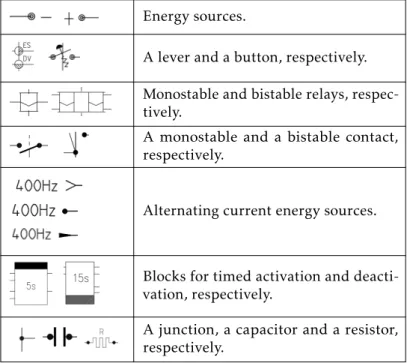
1.2 Representation of electrical components inside relay diagrams. . . 19
1.3 Set notations. . . 36
1.4 Relation, function and sequence notations. . . 39
1.5 B-method notations in unicode and ASCII [Schneider 2001]. . . 43
2.1 Methodologies presented in literature for the relay-based RIS formal specifica-tion. . . 52
3.1 Conditions that must be satisfied for the activation of blocks from each type. . 84
3.2 Number of allowed connections for each type of component. . . 99
4.1 Components state representation mapping. . . 122
4.2 Representation of buttons and lever contacts states inside the relay diagram. . 123
4.3 Inputs values representation mapping. . . 127
4.4 Behavioural and structural definitions that support the relay-based RIS formal specification. . . 137 4.5 Représentation des composants électriques à l’intérieur des diagrammes de relais. 151
List of Figures
1 Diagram presenting the approach proposed in this work for the formal
specifica-tion of relay-based RIS. . . 7
1.1 Railway Signalling Levels Scheme. . . 13
1.2 A monostable relay and its related contacts states. . . 18
1.3 A bistable relay and its related contact states. . . 18
1.4 Example of a solution for the ITCS problem used by SNCF. . . 21
1.5 Example of a circuit that electrifies a light signal. . . 22
1.6 Indication of the block connections as it is depicted inside a relay diagram. . . 23
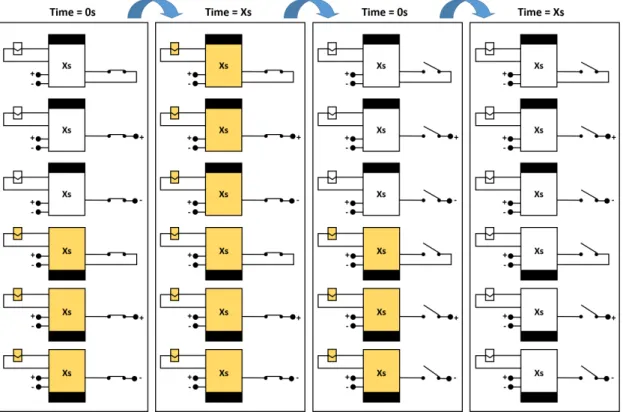
1.7 Succession of blocks states according to their types. . . 23
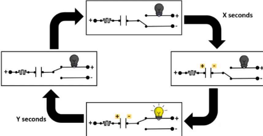
1.8 Simple succession of a capacitor states. . . 24
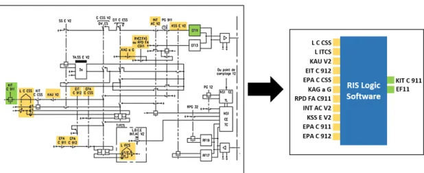
1.9 Representation of a relay-based RIS implemented as a piece of software that communicates with the track-side components through the system inputs (in yellow) and outputs (in green). . . 26
1.10 Track plan representing the normal and the critical situations of the tracks be-tween the control areas A and C. . . 27
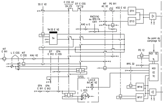
1.11 Partial relay diagram of the solution for the ITCS problem used by SNCF in the Control Area A. . . 27
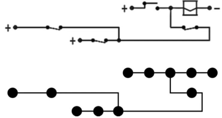
1.12 An example of an electrical circuit and its graph representation. . . 38
1.13 Directed graph representing the electricity flow inside an electrical circuit. . . 39
1.14 Example of a simple B-machine. . . 42
2.1 Some relay diagrams modelling styles: (a) Danish [Haxthausen, Kjær, and Le Bliguet 2011], (b) Italian [Cavada et al. 2018], (c) Ladder-like [Van Eijk 1997], (d) French [Sun 2015]. . . 53
3.1 Description of a specific system based on the RIS general structural and be-havioural formalisation. . . 67
3.2 Possible contacts positions in a relay diagram. . . 70
3.3 Levers states transition example where the small arrows indicate where the current is flowing. . . 72
3.4 Representation of a contact and its connections. . . 74
3.5 Impact of the components states over the system state. . . 76
3.6 A timed activation block (on the left) and a timed deactivation block (on the right). . . 82
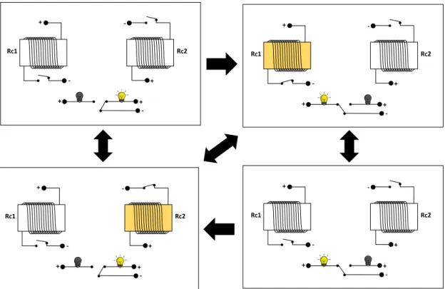
3.7 Different manners to electrify a relay when considering the existence of blocks (the components highlighted in yellow are the ones that are activated). . . 85
3.8 An example of each capacitor type: Positive-negative, Negative-positive and Bipolar, respectively. . . 88
3.9 Block adapted to the use of both direct and alternating currents. . . 95
3.10 ITCS example where components and wires are named. . . 105
4.1 Representation of the components in the RIS logical formalisation and in the B-method formal specification. . . 120
4.2 Relay C_CSS_V2 of the ITCS case study representing the states that this component may assume. . . 121 4.3 Part of the ITCS example showing the separation between the ITCS system and its
environment, which are connected by an external relay. . . 125 4.4 Lever L_ITCS of the ITCS case study representing the states that this component
may assume. . . 126 4.5 Example of a self-powered relay in the ITCS case study. . . 130 4.6 Étude de cas de l’ITCS. . . 152
List of Definitions
Structural Definitions
SD1 Relay Diagrams Graph Structure . . . 68
SD2 Components Differentiation . . . 68
SD3 Levers Structure Definition . . . 72
SD4 Monostable Contacts Connections . . . 74
SD5 Bistable Contacts Connections . . . 74
SD6 Bistable Relays Structural Definition . . . 77
SD7 Structural Relation Between Monostable Contacts and Relays . . . 79
SD8 Structural Relation Between Bistable Contacts and Relays . . . 80
SD9 Blocks Differentiation . . . 82
SD10 Blocks Connections Differentiation . . . 83
SD11 Capacitors Structural Differentiation . . . 88
SD12 Capacitors Structural Definition . . . 89
SD13 Capacitors Plates Potential Charge . . . 89
Behavioural Definitons
BD1 Monostable Contacts States Representation . . . 71BD2 Bistable Contacts States Representation . . . 71
BD3 Buttons States Representation . . . 71
BD4 Levers States Representation . . . 73
BD5 System Disconnections . . . 75
BD6 System Real Connections . . . 75
BD7 Basic Components Electrification Condition . . . 76
BD8 Monostable Relays States Representation . . . 78
BD9 Bistable Relays States Representation . . . 78
BD10 Monostable Relays States Definition . . . 78
BD11 Bistable Relays States Definition . . . 79
BD12 Monostable Contacts States Definition . . . 80
BD13 Bistable Contacts States Definition . . . 80
BD14 Outputs States Representation . . . 81
BD15 Outputs States Definition . . . 81
BD16 Block Passing of Time State Definition . . . 81
BD17 Blocks States Representation . . . 83
BD18 Blocks States Definition . . . 84
BD19 Block-related Electrification Condition . . . 85
BD20 Capacitor Passing of Time State Definition . . . 90
BD21 Capacitors States Representation . . . 91
BD22 Capacitors States Definition . . . 91
BD23 Complete Electrification Condition . . . 92
BD24 Extended Electrification Condition . . . 95 xi
BD25 Extended Blocks Electrification Condition . . . 96
BD26 Outputs Flashing Condition . . . 97
Transformation Directives
TD1 Variables Identification . . . 120TD2 Variables Typing . . . 121
TD3 Safety Properties Specification . . . 122
TD4 Initialisation Definition . . . 124
TD5 Inputs Identification . . . 125
TD6 Inputs Typing . . . 127
TD7 State Evolution Notation . . . 127
TD8 Output State Succession . . . 128
TD9 Monostable Relays State Succession . . . 129
TD10 Self-powered Monostable Relays State Succession . . . 130
TD11 Bistable Relay State Succession . . . 131
TD12 Timed Activation Block State Succession . . . 132
TD13 Timed Deactivation Block State Succession . . . 132
List of Publications
The following is a list of publications produced during the course of this PhD research.
Journals
1. de Almeida Pereira, D. I., Perin, M., Bon, P., & Collart-Dutilleul, S. (2019). A framework for the formal specification of relay-based systems based on a b-method graph specification. International Journal of Computer and Electrical Engineering (IJCEE), 11(1), 11-19. 2. Martinez, S., de Almeida Pereira, D. I., Bon, P., Collart-Dutilleul, S. & Perin, M. (2020, July).
Towards Safe and Secure Computer Based Railway Interlocking systems. International Journal of Transport Development and Integration, 4(3), 218–229.
3. de Almeida Pereira, D. I., Himrane, O., Beugin, J., Bon, P. (2020). From French National Signalling Systems to ERTMS: Considering the Evolution of Track-side Systems. Interna-tional Journal of Signal Processing Systems (IJSPS), in press.
Conferences
1. de Almeida Pereira, D. I., Malki, O., Bon, P., Perin, M., & Collart-Dutilleul, S. (2018, October). An MDA approach for the specification of relay-based diagrams. In International Conference on Model and Data Engineering (pp. 17-29). Springer, Cham.
2. de Almeida Pereira, D. I., Deharbe, D., Perin, M., & Bon, P. (2019, June). B-specification of relay-based railway interlocking systems based on the propositional logic of the system state evolution. In International Conference on Reliability, Safety, and Security of Railway Systems (pp. 242-258). Springer, Cham.
3. de Almeida Pereira, D. I., Debbech, S., Perin, M., Bon, P., & Collart-Dutilleul, S. (2019, November). Formal Specification of Environmental Aspects of a Railway Interlocking Sys-tem Based on a Conceptual Model. In International Conference on Conceptual Modeling (pp. 338-351). Springer, Cham.
General Introduction
Context
With the advance of the technology, modern electronic systems are becoming more and more important in the human life as the automation of essential tasks is taking place in the people routines. In some cases, these systems are responsible for such important tasks that their correct functioning is crucial in order to avoid severe repercussions. When the consequences of a failure result in loss of life, significant property or environmental damage or another unacceptable consequence, these systems are considered as safety-critical, which requires more advanced approaches for the verification of their correctness in order to avoid hazardous situations [Knight 2002]. Some examples of these systems are Aircraft Flight Control, Railway, Medical Devices and Nuclear Systems. In this context, the use of modern verification approaches may be the differentiating factor in order to guarantee the safety of these systems.
In the railway context, Railway Interlocking Systems (RIS) are an example of safety-critical systems. The RIS are the part of the railway signalling systems that controls the trains movements in order to prevent hazardous situations like collisions or derailments. With the objective of avoiding the occurrence of several problems like the loss of people lives, injuries, severe environmental damage and economical loss, for instance, the safety of RIS must be guaranteed. Thus, the technologies used by the railway companies for the development of such systems must be able to detect and prevent hazardous situations before their implementation and use.
In general, these systems can be implemented using some different technologies, like relay-based or computer-controlled, this last one being the most recent [Hansen 1998a]. In some cases, the relay-based technology has been used for decades in such a way that the existing interlocking systems are recognised as safe. Nonetheless, despite the historical success of relay-based RIS, computer-based systems are easier to handle and maintain, cheaper and more adaptable to functional requirements changes [Akita et al. 1985]. The use of new technologies is an industrial interest due to their benefits, however, the preservation of the system safety level is a strong requirement in order to replace the existing systems. Thus, the transformation of the existent well succeeded relay-based systems into safety-proved computer-controlled ones can be extremely beneficial in both economical and safety aspects.
In order to prove the safety of a system and support its implementation, Formal Methods may be used. Grounded on a strong mathematical foundation, formal specification methodologies allow the system modelling based on mathematical expressions as a way to define and prove system properties. Currently, there exist several different formal languages documented, each one with a different focus and capable to specify different aspects of the systems. Furthermore, many
formal languages have well-defined refinement methodologies that allow the transformation of the abstract system models into concrete models that may be implemented as software. Some of these languages are supported by tools that automate the process of verification and refinement. Thus, the use of Formal Methods may be the key in order to specify, safety prove and transform the existing relay-based RIS into computer-controlled ones by refinement. The B-method [J.-R. Abrial, Lee, et al. 1991] is one example of a formal language that, together with its supporting tools, allow the system specification, verification, analysis, refinement, implementation and automatic code generation. In fact, the B-method has been already successfully applied in industrial railway projects ([Behm et al. 1999], [Lecomte, Servat, Pouzancre, et al. 2007]).
In this context, the LCHIP (Low Cost High Integrity Platform) Project1aims at the implemen-tation of safety-proved computer-based RIS based on the existing relay-based systems used by the French National Railway Company2(SNCF - Société Nationale des Chemins de fer Français). It is a project funded by the Unique Interministerial Fund (FUI) and developed by a consortium coordinated by Clearsy3and combining the work from different partners, like SNCF and Univer-sité Gustave Eiffel4. One of the major objectives of this project is to use the B-method as a tool for
the specification, safety proving and implementation of the logic behind the existing relay-based RIS in the form of programming code. By following this procedure, it is possible to produce safety-proved computer-based Railway Interlocking Systems whose execution logic is the same of its predecessor technology. Then, these computer-based RIS may run in micro-controllers that can replace the existing relay-based systems as a way to evolve them towards a new technology that is safer, extendable and maintainable.
This doctoral dissertation presents part of the research developed inside the LCHIP Project in the laboratory ESTAS of the Université Gustave Eiffel. It presents a methodology for the specification of relay-based RIS behaviour based on a formalisation of the information contained inside the relay diagrams used by SNCF. The mathematical formalisation of these diagrams as well as their formal specification represent the initial steps towards the implementation of the existing relay-based RIS as computer-based systems as envisaged by the LCHIP Project. In this thesis, the B-method is used as the formal language that supports the specification of these systems. As a result, it is possible to perform proofs regarding the system safety and continue the formal development life-cycle as a way to implement relay-based RIS as computer-based systems.
Problematic
The first built RIS was purely mechanical, than it evolved to use new technologies, becoming electromechanical systems, relay-based systems and, more recently, computer-controlled systems [Hansen 1998a]. Despite the existence of a new technology, relay-based RIS are still used by many railway infrastructure managers, like SNCF. This choice can be explained by the historical success of this technology in addition to the lower complexity and unequivocally defined fault modes [Pasquale et al. 2003]. Although ancient systems have been tested enough to be considered
1Low Cost High Integrity Platform - https://www.clearsy.com/en/4260-2/ 2https://www.sncf.com/
3https://www.clearsy.com/ 4https://www.univ-gustave-eiffel.fr/
safe, their maintenance and the development of new relay-based systems must face a known problem in this type of system: the difficult, time consuming and error prone verification process.
Relay-based Railway Interlocking Systems are generally modelled by electrical circuit draw-ings named as relay diagrams, which present the structure of the systems based on the electrical connections between the components. This structural model possesses a certain level of formali-sation as modelling rules are followed for the system design, although each company defines its own patterns and guidelines. Nevertheless, the lack of a behavioural description makes the safety verification an arduous and error prone process as the system behaviour must be deduced from the relay diagrams. Thus, in order to verify the safety of relay-based RIS, an expert must manually inspect the relay diagrams and draw conclusions about the system safety.
“Due to the high number of diagrams and their mutual correlation, this process is complex, time consuming (and thus expensive) and possibly error prone, which is not satisfactory for a safety critical system" [Haxthausen, Le Bliguet, and Kjær 2008]. Besides, as each person may have a different
interpretation of the system behaviour based on the modelled structure, this process is subject to ambiguity. As a consequence, the models inspection cannot be completely trusted. Moreover, after the manual verification, it is necessary to perform tests in the field. This is an important step in every system as a way to guarantee the correct functioning. Nevertheless, as the system safety cannot be guaranteed, this process can be costly and even risky in some cases.
In such circumstances, the industry needs a more effective approach for the verification of the relay-based Railway Interlocking Systems in order to guarantee their safety. In this context, the European EN50128 guidelines [CENELEC 2011], issued by the European Committee for Electrotechnical Standardisation5(CENELEC), strongly recommends the use of Formal Methods for the specification of systems/components during the development of railway systems. Formal specification methodologies allow the proof of the system safety by modelling its behaviour based on mathematical expressions, which can be used as basis for formal verification processes. So, the use of modern formal specification approaches is not only necessary, but it is also strongly recommended by the railway standards.
Furthermore, as the computer-based technology offers some benefits like a better maintain-ability and extensibility when compared with the relay-based systems, the railway industry has interest on evolving its systems. Nonetheless, before implementing a new solution, it is impera-tive to guarantee that the new system safety level is at least equal or better than the precedent technology. This is because the existing relay-based systems are generally already recognised as safe. Moreover, the adaptation of the new system regarding the existing installations must be considered as the industry demands a cost-effective solution.
In conclusion, despite the success of the relay-based technologies, it is a fact that the safety verification of the relay-based RIS can be costly and error prone. As a way to solve this problem and conform to the railway standards, the railway industry needs to be adapted to use modern formal verification approaches, which is able to give a guarantee of the system safety based on their mathematical foundations. Due to the benefits of the use of computer-based technologies, the industry has interest on using this type of technology. Nonetheless, it is important to take precautions in order to maintain the system safety and make this system evolution cost-effective. In this context, the creation of an approach capable of formally verifying the relay-based RIS
and promoting their evolution to computer-based systems maintaining their execution logic can be extremely beneficial to the industry as a way to guarantee the system safety and maintain their previous functioning logic.
Motivations and Objectives
In this present thesis, there is a strong interest on analysing and improving the railway systems as a way to guarantee their safety. The problems faced by the industry regarding the relay-based RIS safety proof require a study about the context of application, the techniques and tools that may be used as well as the experiences of other works in this field. This thesis is also a conciliation between the Railway and Formal Methods areas, which demands a special attention in order to integrate the knowledge, experiences and tools of both fields. Relay-based systems have their own logic and functioning. As a result, the process of formally specifying these systems has a tendency to be a challenging task. A careful analysis of these systems is imperative in order to support their formal specification.
The existence of modern technologies compared to the ones used in the relay-based systems and the industrial interest on evolving their systems are some of the motivations of this work. This is because these technologies can introduce new benefits that were not supported in the preceding systems. Formal specification methodologies has gaining space in the railway field and they have proved their effectiveness by the successful documented experiences about their use. In consonance, the European Committee for Electrotechnical Standardisation recognised the importance of the Formal Methods in this area and strongly recommended its use in the last versions of the norm EN50128 [CENELEC 2011]. All these facts only reinforce the interest on using this technology in our relay-based context.
The formal specification of the existing relay-based Railway Interlocking Systems can support their formal verification as a way to guarantee their safety. Furthermore, the use of a formal spec-ification language that supports a formal development process may allow the implementation of the relay-based RIS as safety-proved computer-based systems. The creation of an approach to support this formal specification is the most fundamental aim of this present thesis, which can be resumed in the following research objective:
RO1: How to formally specify the existing relay-based RIS as a way to be able to verify and implement these systems by refinement?
However, it is important to consider that there is a communication problem between the Railway and Formal Methods experts as they may occasionally do not share the same knowledge. Generally, railway experts have a small background on working with formal specification. Similarly, Formal Methods experts typically have none or few experiences on the railway field. In this context, a solution presented for the formal specification of relay-based RIS must be understandable for experts of both fields. Based on these considerations, it is possible to formulate a second research objective as:
RO2: How to formalise the relay-based RIS in a manner that it can be comprehensible to the different experts involved?
In the French context, which is the focus of this thesis, relay diagrams are used as models that guide the system implementation. As these models are the most important documentation of these systems, they can also be used to guide an approach for the relay-based RIS formal specification. However, one must take into consideration that each railway company uses a different set of electrical components and different design rules for drawing the relay diagrams. In this situation, it is important to provide a solution that can be extended in order to conform to other contexts and design rules. Thus, it is possible to formulate the third research objective as: RO3:How to create a formal model of relay-based RIS that can be extended as a way to support different contexts?
This latter research question is related to the consideration of the railway system context. However, one must also acknowledge that the formal specification language chosen to specify such systems may impact on the verification that can be performed. This is because every language focuses on different aspects of the system and is able to verify different properties. The literature regarding the use of formal specification languages presents many successful examples that can be adopted, so it is desirable that the RIS formal specification approach can be adapted in order to allow the specification of these systems in different formal languages. In this context, it is possible to define a last research objective:
RO4:How to define an approach for the formal specification of relay-based RIS that can be adapted to use different formal specification languages?
As presented in the research objectives, this thesis aims not only at the formal specification of the relay-based Railway Interlocking Systems, but also the development of an approach that can be used in many contexts and that can be adapted for the verification of different aspects of the system. Furthermore, we consider it important the creation of a model that can be understood by different experts involved. The next section presents the main propositions of this work in order to answer these research objectives.
Contributions
After an extensive analysis of the use of Formal Methods for the specification of relay-based Railway Interlocking Systems in literature, it is possible to observe that there are not many works with the objective of formalising these systems. The contributions in this field are mostly focused on the computer-based RIS formal specification and implementation based on a higher level of abstraction of the interlocking procedures. Besides, the existing approaches are generally devoted to the specification of these systems from a specific context and in a specific formal language.
In order to formally specify the existing relay-based RIS, this work proposes a complete structural and behavioural analysis of the relay diagrams used by the SNCF. In this analysis, the structural design and the behavioural logic are studied in order to define the relations between the components and produce a more formal model which can be then used as basis for the system formal specification. By following this approach, it is possible to maintain the system execution logic. Furthermore, it allows the definition and verification of safety properties as a
way to guarantee the system safety.
The formal specification approach chosen in order to specify these systems in this thesis is B-method, due to its successful history in the railway field, strong mathematical background, support to a complete formal development process and the existence of supporting tools for the implementation, analysis, automatic verification and implementation of the systems. Based on the formalisation of the information contained inside the relay diagrams, this work proposes an approach for the adaptation of the formalised logic in order to conform to the B-method syntax. Once formally specified, it is possible to benefit from the advantages of this language in order to verify and implement the relay-based RIS as safety-proved computer-controlled systems, answering the Research Objective 1.
With the objective of formalising the relay-based RIS in a manner that it can be comprehen-sible to the experts involved, this work proposes the analysis of the relay diagrams based on basic mathematical foundations that are generally studied and understood in all the exact and technological sciences. So, it is proposed to use a graph in order to model the electrical circuit network and the application of First Order Logic and Set Theory as a way to define the structural and behavioural relations between the electrical components. This analysis and formalisation of the systems allow a manual formal verification of the structure well-definedness and the behaviour safety. Furthermore, this analysis proposes a model that can act as a middle course between the structural relay diagrams and the behavioural formal specification, providing a common understanding of the system for the experts of both areas and answering the Research Objective 2.
The use of basic mathematical foundations also provides an extendable and adaptable model that can be adjusted to many different railway contexts, which is our Research Objective 3. The formalised model does not impose limits to the components that may be specified and the logic used allows the specification of the behaviour of a great variety of electrical components. Besides, all the components found in literature are used in the SNCF context. As a consequence, this work presents a non-exhaustive list of components structural and behavioural formalisation that can be used for the system formalisation in many different contexts.
Another benefit of modelling the system with basic mathematical foundations is the possibil-ity of adapting this model to conform with many different formal languages. This is because Set Theory and First Order Logic are some of the most basic foundations of many formal specification languages. So, the expressions used in the relay diagrams formalisation model can be adjusted to the syntax of languages like B-method, for instance. By proposing an approach that can support the formal specification of the relay-based RIS in many different formal specification languages, this work also answers the Research Objective 4.
So, the main contributions of this thesis is the analysis and formalisation of the information contained inside a relay diagram using strong mathematical foundations. This formalisation generates a model that can be adapted and extended in order to conform to different railway contexts. Besides, it can be used to support the formal specification of these relay-based systems in many different formal specification languages due to the common mathematical background. In this work it is also proposed an adaptation approach in order to formally specify the SNCF relay-based RIS in the B-method, which is a method that can support the automatic safety verification and the use of a formal development process for the generation of computer-based
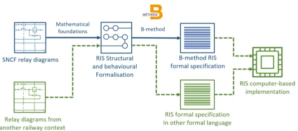
systems. Figure 1 depicts a diagram that presents the approach proposed in this work for the formal specification of the relay-based RIS. The solid lines represent the approaches that are detailed in this thesis, while the dashed lines demonstrate the alternative processes that are supported by these approaches.
Figure 1 – Diagram presenting the approach proposed in this work for the formal specification of relay-based RIS.
Outline
This manuscript is divided into five main chapters and a general conclusion that are distributed into three parts. The first part of this thesis is devoted to the preliminaries, presenting the back-ground of our work and the state of the art in the literature regarding the formal specification of Railway Interlocking Systems. Then, the second part of this work is devoted to the methodology construction, where it is detailed an approach for the formalisation of the existing relay-based RIS based on mathematical foundations. Then, as presented in this same part, this formalisation may be adapted for the formal specification of these systems in the B formal language. The last part of this thesis is the conclusion, providing a summary of what has been presented and discussing some new research opportunities that result from this work.
In Chapter 1 it is presented the background, i.e., all knowledge that grounds the approaches presented in this thesis. In this chapter, we detail all the information necessary in order to understand the formalism and notations used in the next chapters. It begins by contextualising the railway systems and signalling as it presents the characteristics and safety aspects of these systems. Furthermore, the different types of Railway Interlocking Systems are discussed and detailed and a real industrial case study is presented. Then, this chapter introduces the formal specification methodologies and the mathematical foundations that are used in our approach for the relay-based RIS formalisation. These mathematical foundations are: Propositional and First Order Logic, Set Theory, Relations, and a graph description based on Set Theory. In fact, some of these foundations are also the basis for the B-method syntax, which is also discussed at the end of this chapter. The use of this language in industrial and academic works is also discussed.
Chapter 2 is devoted to the state of the art of this work, i.e., it discusses the use of for-mal specification methodologies for the analysis, verification and implementation of Railway Interlocking Systems as presented in the literature. This chapter is divided according to the system level of abstraction and the objectives of each presented work. Regarding the level of abstraction, it analyses the use of Formal Methods for the specification of systems focused on the dispatchers and interlocking levels. Then, concerning the latter level, this chapter discusses the approaches that propose the formal specification of relay-based RIS, the ones that propose the implementation of interlocking systems with computer-based technologies and other unusual approaches that contain some similarities to the objectives of this present thesis. Thus, it focuses in positioning our work regarding to what has already been presented in the literature, by discussing how the existing solutions cannot solve our problematic, but are still inspiration to our proposed solutions.
The first chapter of Part II is Chapter 3. In order to be able to formally specify the structure and behaviour of relay-based RIS, this chapter presents a mathematical description of the information contained inside relay diagrams. Based on First Order Logic and Set Theory, it is presented how a graph structure may be used in order to represent the relations between the RIS electrical components. Then, the state of each component is represented and defined in relation to the state of the others. This state definition allows the description of the system behaviour based on the specific behaviour of each component. Furthermore, the impact of the time constraints demanded by some determined components over the system general state is also discussed. As this formalisation is based on mathematical notations, it can already be used as a way to prove determined structural well-definedness and behavioural safety aspects, as it is detailed in this chapter. Then, a case study is analysed according to the generated formalisation model and the results are presented.
The next chapter (Chapter 4) details how the relay-based Railway Interlocking Systems may be formally specified from the relay diagrams by using the behavioural formalisation as a middle course. The B-method is used as formal language and methodology due to its success in the railway field as well as its support for First Order Logic and Set Theory. In this specification approach, the behavioural formalisation described in the previous chapter may be adapted in order to conform to the abstractions provided by the B-method as a way to create a mathematical description that can be verified by the supporting tools. Furthermore, the mathematical description is adapted in order to use the state evolution support given by the formal language as a way to prove the system safety in the complete system state-space. A case study is specified and the results of the formal verification is presented and discussed.
The last part of this thesis (Part III) concludes this manuscript by presenting a summary of the conducted work and the obtained results. Moreover, as this work creates new research opportunities, many future works are presented, like the use of the behavioural formalisation for the specification of relay-based RIS with the use of other different formal languages, or the creation of a specific refinement methodology for the implementation of these systems as computer-based systems with well-defined inputs and outputs. All these research opportunities are detailed and discussed in this last part, concluding that a thesis work is only a small and important step towards multiple research directions.
Chapter
1
Background
Contents
1.1 Introduction 12
1.2 Railway Systems and Signalling 12 1.2.1 Safety-critical Aspects in the Railway Field . . . 14 1.2.2 Relay-based and Computer-controlled RIS . . . 17 1.2.3 Case Study . . . 26 1.3 Formal Methods and Mathematical Foundations 30 1.3.1 Formal Specification Methodologies . . . 30 1.3.2 Propositional and First Order Logic . . . 31 1.3.3 Basics of Set Theory and Relations . . . 34 1.3.4 Graph Description Based on Set Theory . . . 38 1.3.5 The B-method . . . 41
1.1
Introduction
The railway domain contains several examples of critical systems, whose failures may cause severe consequences like the loss of people lives. The Railway Interlocking Systems (RIS) are one of these examples. As part of the signalling systems, the RIS are responsible for controlling the trains movements in a safe manner in order to avoid hazards. These systems can be implemented by using many different technologies, the computer-controlled systems being the most recent and industrially beneficial.
However, many companies still use relay-based technologies in order to implement the Railway Interlocking Systems. This can be explained by their historical use and the safety provided by this technology regarding possible dysfunctional problems. The transformation of the existing relay-based RIS into computer-based RIS are under the interest of the industry as a way to maintain the system operation with the same or even improved safety level. The use of formal specification methodologies may be the key in order to produce safety-proved computer-based RIS, since their mathematical background may support the formal specification, analysis and verification of the relay-based systems as well as their implementation through refinement.
Nonetheless, before presenting the approaches for the formal specification and implemen-tation of these systems, it is important to understand the role of these Railway Interlocking Systems in the Railway Systems as well as their safety-critical aspects. Furthermore, one must comprehend the differences between the RIS abstract levels and the different technologies that can be used for their implementation.
In this chapter all the details regarding the Railway Interlocking Systems are discussed, which is necessary for understanding the work presented in this thesis. A case study of a real example provided by the French National Railway Company (SNCF) is also detailed as a way to demonstrate the importance of the safety guarantee in these systems.
Then, this chapter provides a discussion about the formal specification methodologies and their use. As a way to support the mathematical formalisation and specification of the RIS, all the mathematical foundations necessary in order to ground our methodology are detailed. These foundations are also the basis of many formal specification languages, like B, for instance. A discussion about the B syntax, supporting tools and successful academical and industrial use concludes this chapter.
All the background information presented in this chapter are essential in order to fully understand the work presented in this thesis. The industrial case study discussed here is used as an example throughout the whole manuscript. Furthermore, the discussion about the safety aspects of these railway systems and the examples of successful use of the B-method in railway industry reinforce the need of the use of formal methodologies for the development of railway systems.
1.2
Railway Systems and Signalling
The railway means of transportation was the first to have mass mechanised movement. After its creation, its velocity, supporting weight and length has constantly increased. According to [Theeg 2017], all railway systems may be identified by two features:
• The train path is determined by the mechanical guidance system comprised by wheels, rails and turnouts;
• The train may move at high speeds in a way that its wheels poor braking response may require a breaking distance longer than what is visible by the driver, so precautions must be taken in order to safely control the train movements.
On its most basic structure, a railway system is composed by steel wheels, rails (tracks) and turnouts, being this last one the way how trains may change their direction. The steel material allows the system to withstand heavy transits, but its low adhesion coefficient impacts negatively on the breaking capabilities. In order to make the regulation of traffic and the prevention of accidents, Railway Signalling Systems are responsible for detecting data like the trains positions and track availability, process them and control the trains movements and other track components.
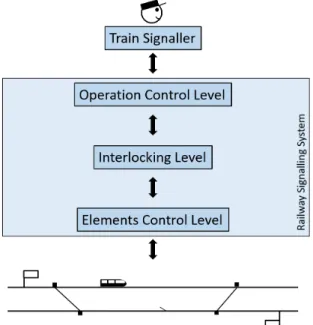
Railway Signalling Systems are subdivided into three levels: the Element, Interlocking and Operation Control levels, as presented in Figure 1.1. The Element Control Level is the interaction between the system and field elements like train detectors, turnouts and signals. This is the part of the system responsible for controlling and monitoring the track electrical and mechanical components. The Interlocking Level is the part of the system responsible for processing the data and responding accordingly to safety aspects as a way to avoid dangerous situations. Then, the Operation Control Level is the interface between the system and the signaller, i.e., the person that induces the train movement. Thus the safety of the system depends on the Interlocking Level capabilities of processing the data and sending the correct information to both Element and Operation Control levels.
Figure 1.1 – Railway Signalling Levels Scheme.
Above the Operation Control Level, there is the train signaller, which is the responsible for directly inducing the train movement. The signaller decisions are made based on timetables, signalling rules and the current situation. The train traffic management schedules are produced
in the form of timetables by the dispatchers, which have the objective of organising a well-thought train schedule and communicate with signallers any unexpected situation. The Dispatchers Level is right above the Signaller Level in the Railway Signalling level hierarchy.
In order to guarantee the safety of these Railway Interlocking Systems, the Interlocking and the Dispatchers levels must be analysed. In the Interlocking Level it is necessary to guarantee that the system is indeed executing accordingly to safety aspects and avoiding any hazardous situations, which requires a deep analysis of the logic behind these systems. In the Dispatchers Level, one must assure that the timetables do not cause a dangerous situation by avoiding any proximity between trains during their route. Although these analysis have the same objective of guaranteeing the system safety, they are made in completely different manners that require different approaches. While the verification of interlocking systems is made regarding a specific local situation, the verification of timetables requires the analysis of several train routing in order to guarantee that they do not share the same track point. Both works are extremely important in order to guarantee the system safety and many methodologies and studies have been made in both areas. This thesis focuses on the analysis and verification of the systems in the Interlocking Level.
1.2.1
Safety-critical Aspects in the Railway Field
The main concern about safety-critical systems is with the consequences of failure [Knight 2002]. In this case, a failure may be defined as an external incorrect behaviour according to the system requirements and the expected behaviour [Ammann 2016]. When a failure leads to acknowledged unacceptable consequences, the system is determined as safety-critical. Some well known examples of traditional areas where safety-critical systems are applied are medical devices, aircraft flight control, weapons, and nuclear systems [Knight 2002]. In the railway field, the safety-critical nature of railway systems is evident, since a failure may cause severe consequences like the loss of people lives, substantial economical loss and even extensive environmental damage.
The safety in this context is related to the"functional safety within the system and protection against hazardous consequences caused by technical failure and unintended human mistakes" [Theeg
2017]. Given that an error is an incorrect internal state of the system [Ammann 2016], the system safety may be achieved by avoiding the occurrence of errors through a careful inspection before putting the system into operation. Nevertheless,"a spontaneous (random) faillure during operation cannot be prevented. However, dangerous consequences of such a failure can be prevented by the design of the system" [Theeg 2017].
According to [Schön et al. 2013], the railway operation presents five major problems: 1. Collision between trains that go in the same direction in the same track in different speeds; 2. Collision between trains that have converging routes;
3. Frontal collision between trains that travel in the same track in opposite directions; 4. Collisions at a road level crossing;
Except for derailments, all the other cited problems are related to collisions while the train is under its route. The causes of these accidents are numerous, but the human factor and equipment defect are some of the most significant causes [Liu, Saat, and Barkan 2012]. Regarding derailments, for instance, it is known that at low speed, they are mostly caused by certain track and human factors, like improper train handling, braking operations and improper use of turnouts (points). At higher speeds, these problems are mostly caused by equipment defects [Liu, Saat, and Barkan 2012]. While human erroneous decisions are difficult to predict and control, the correct operation of interlocking systems may guarantee the non-occurrence of some problems when considering that their instructions are well followed by all the related humans. In this case, although the signalling installations can solve the railway operation problems, it does not diminish the importance of regulation, since the obedience to signal indications and exceptional procedures are a matter of regulation [Rétiveau 1987].
Table 1.1 – Some railway signals presented in [Rétiveau 1987].
Green Signal -Normal operation is authorised, if there are no objections.
Yellow Signal -It is necessary to be able to stop before the next stop signal.
Double horizontal yellow Signal -Commands to not ex-ceed the speed of 30km/h when passing over the corre-sponding turnout.
Double horizontal flashing yellow Signal -Commands to not exceed the speed of 60km/h when passing over the corresponding turnout.
Red and purple Signals -Instructs to stop in front of the signal.
In order to indicate the safe procedure for a train in its route, railway signals are used. In the french context, light signals are used as stop, speed limit and direction signs [Rétiveau 1987], as presented in Table 1.1. As the interlocking system is also responsible for controlling the railway turnouts, they must guarantee that a train only passes through them when they are placed and locked, since an unexpected switch movement may cause the derailment of the train that is using it. Together with the signals that control the train speed, a RIS whose instructions are well followed have the responsibility to avoid the occurrence of collisions and derailments in
several different situations. Therefore, the logic of these systems must be safety proved as a way to guarantee the absence of accidents.
In the European context, the electrical engineering standardisation is a responsibility of CENELEC, the European Committee for Electrotechnical Standardisation (Comité Européen de Normalisation Électrotechnique). Some of the most important European Norms (EN) regarding the railway systems development and operation are the EN 50126 [CENELEC 2017a][CENELEC 2017b], EN 50128 [CENELEC 2011] and EN 50129 [CENELEC 2018].
Regarding the safety, EN 50126-1 [CENELEC 2017a] provides a Safety Management Process for the Railway Systems development. This process is supported by the guidance and methods presented in the EN 50126-2[CENELEC 2017b]. The approach defined in EN 50126 is consistent with the application of quality management requirements defined in the ISO 9001 [ISO 2015]. This norm also defines several terms, like:
• Accident –“unintended event or series of events that results in death, injury, loss of a system or service, or environmental damage";
• Error –“discrepancy between a computed, observed or measured value or condition and the true, specified or theoretically correct value or condition";
• Failure –“loss of ability to perform as required”;
• Hazard –“condition that could lead to an accident”;
• Reliability –“ability to perform as required, without failure, for a given time interval, under given conditions”;
• Risk –“combination of expected frequency of loss and the expected degree of severity of that loss”;
• Safety –“freedom from unacceptable risk";
• Safe state –“condition which continues to preserve safety”;
• System –“set of interrelated elements considered in a defined context as a whole and separated from their environment";
• Subsystem –“part of a system, which is itself a system”;
• Verification –“confirmation, through the provision of objective evidence, that specified require-ments have been fulfilled”.
While EN 50126 addresses system issues in a widest scale, EN 50128 concentrates on the methods for the development of software that complies with the safety demands. In this context, Software is defined as"intellectual creation comprising the programs, procedures, rules, data and any associated documentation pertaining to the operation of a system". This norm also defines five
software Safety Integrity Levels (SIL), being SIL0 the lowest and SIL4 the highest one, measuring the risk resulting from software failure. Furthermore, the EN 50128 gives recommendations of techniques and measures according to each Safety Integrity Level. For instance, the use of Formal Methods of specification based on a mathematical approach is recommended for systems SIL1 and SIL2, but it is highly recommended for systems SIL3 and SIL4.
Regarding the electronic part of the signalling system, the safety-related acceptance require-ments of electronic systems are defined in the EN 50129. During the execution of a signalling system, one must consider that problems caused by electrical components defects are hard to predict and prevent. These problems can be mitigated by the use of ancient relay-based Railway Interlocking Systems, which have lower complexity and unequivocally defined fault modes [Pasquale et al. 2003]. Nevertheless, these systems are difficult to model, safety proving and maintain. Thus, they are being replaced by computer-controlled systems, which are easier to handle and maintain, cheaper and more flexible to extend functions [Akita et al. 1985]. Each of these technologies have their advantages and disadvantages, which are discussed in the next section.
1.2.2
Relay-based and Computer-controlled RIS
In the beginnings of the railway operations, all the interlocking procedures were made by humans, which had the responsibility of manually interacting with the field elements [Theeg 2017]. This "interlocking" procedure is not a real interlocking, since no technical locks are provided. For safety reasons, this procedure was widely replaced by mechanical systems. In fact, the first Railway Interlocking System was purely mechanical. Then, as electricity became common, the mechanical systems evolved to electromechanical relay-based systems. More recently, computer-based technology is replacing the electrical systems [Hansen 1998a]. Nowadays, many railway infrastructure managers are replacing the existing relay-based systems by computer-based technologies.
Some of the first steps towards the use of electrical components in the RIS started around 1870, with the development of partial electrical systems beginning around 1900. But it was only between the two world wars that the firsts relay-based RIS were developed and installed in various countries. This type of system is still used in the majority of existing installations [Theeg 2017]. However, With the existence of more advanced technologies, the relay-based systems are being replaced by the computer-based ones (electronics).
Relay-based Systems and Modelling
Relay-based RIS are implemented in the form of electrical circuits whose electrical current flux is controlled by relays. As an electromagnetic component, a relay is composed by a electromag-net (coil) and a movable armature containing one or more electrical contacts. When electrified, the relay coil produces a magnetic field that attracts the armature, changing the contacts posi-tions, which may open or close circuits according to their initial positions. Figure 1.2 depicts the states of a relayR and its related contacts C1, C2 and C3. By controlling the flux of electrical
current in other wires, the alteration between the relay states may activate or deactivate other relays, which creates a chain effect until the system reaches a stationary state, i.e., the moment where no component has its state altered.
Relays are divided into two different kinds: Monostable and Bistable. The main difference between them is the impact of the gravity on their states. A monostable relay contains only one electromagnetic coil that pulls the contacts against gravity. In this case, the contacts are physically disposed horizontally so they can fall down when the coil is not energised, as presented in the Figure 1.2. A bistable relay, on the other hand, has two electromagnetic coils that pull
Figure 1.2 – A monostable relay and its related contacts states.
vertically positioned contacts to different sides, as presented in the Figure 1.3. The contacts are attracted to the energised coil. The relay coils positions are typically called as "left" and "right" [Schön et al. 2014]. Furthermore, if both bistable relay coils are activated or deactivated, gravity causes the contacts to maintain their previous states.
Figure 1.3 – A bistable relay and its related contact states.
The contacts related to monostable relays, the monostable contacts, may be divided into three categories: normally-open, normally-closed and changeover contacts [Schön et al. 2014], which are represented in Figure 1.2 as the contactsC1, C2 and C3, respectively. A
normally-closed contact is closed when the relay is deactivated and open otherwise. In the case where a contact is able to establish a connection independently of the relay state, it is called as a changeover contact, since it is able alternate between two different connections.
The differentiation of contacts types is important because the most stable state of a monostable relay is the deactivated state, i.e., when it is not energised. As the contact falls down by gravity, this position is called as the "safe position" as it is used in order to keep the system safety in case of a component failure. In this case, the system must always give an information that can only leads to a safe state, thus the "down" position of a contact generally leads signals to be red or detectors to indicate a train presence. Besides, relays are made following strict compliance requirements so they can be trusted during a system execution. An example of the dysfunctional safety guarantee given by relays is detailed in the case study presented in Section 1.2.3.
Before their implementation as electrical circuits, relay-based RIS are generally modelled as electrical circuits schemata named relay diagrams. They represent in a graph format how the electrical components are connected by wires. Nonetheless, there is not a unique approach for drawing relay diagrams, as each company has its own set of electrical components and design rules. Although some diagrams may be similar, their representation may have a big impact on how the system behaviour may be understood from the drawings. This thesis focuses on the relay diagrams representations given by the French National Railway Company (SNCF) and their documentation in [Rétiveau 1987] and [Schön et al. 2014].
Besides the relays, many other components may be used in the implementation of relay-based RIS and modelled inside a relay diagram. Table 1.2 presents how some of these electrical components are graphically represented. Each component has its specific behaviour and plays an important part on the complete system exececution.
Table 1.2 – Representation of electrical components inside relay diagrams.
Energy sources.
A lever and a button, respectively. Monostable and bistable relays, respec-tively.
A monostable and a bistable contact, respectively.
Alternating current energy sources.
Blocks for timed activation and deacti-vation, respectively.
A junction, a capacitor and a resistor, respectively.
determined components. Generally, a component is electrified when connected to both energy sources poles, negative and positive. Nonetheless, components may also be electrified when connected to other more complex components, like blocks or capacitors, as discussed later. However, even these components require a connection to energy sources in order to function correctly.
It is also possible to define an interface that allows the system user to control the electricity flow inside the wires as well as obtain important information about the system state. This interface may be implemented by the use of buttons and levers as the system inputs, and lights and antennas for the system outputs. A button allows the environment to control the current flow in one single wire, since this component acts like a contact that requires physical force in order to close. A little more complex than buttons, levers allow one to control the flux of electrical current in many wires at the same time. Levers are connected to a set of contacts which always alternate their states together. When the lever state changes by an environmental physical force, all its related contacts alternate their states together, blocking and allowing the current to flow in different wires at the same time.
Monostable relays and bistable relays are represented inside relay diagrams as single and doubled coils, respectively. Each coil has two independent connections to wires. The relation between relays and contacts are represented as a semi-dotted vertical line, as presented in the example of the Figure 1.4. This figure represents a solution for a Temporary Reversed Direction Installation (ITCS - Installations Temporaires de Contre Sens), given by SNCF, discussed with more details in Section 1.2.3.
As a way to improve readability, bistable relays and levers may have specific names for each of their states. These names are generally related to the effect of these components states over the rest of the system. A lever may have the names "on" and "off" for each of its states and a bistable relay may have the states "in service" and "out of service" instead of "left" and "right", for instance.
Relays may also be considered as inputs or outputs of the system in determined situations. When the relay is not presented inside the diagram but its related contacts have influence on the system execution, this relay is considered as an input. In this case, the relay is considered as part of the environment, since it is not controlled by the modelled system. Furthermore, if the relay is presented inside the diagram, but its related contacts are not part of it, this relay is an output, since it impacts the environment through its contacts. Indeed, any relay may be an output, as long as it has at least one contact that is not presented inside the diagram. In this case, the interpretation of the diagram and the knowledge about the system is extremely important in order to define what is indeed an output or not.
One of the possible system outputs are the light signals. Differently from the rest of the system, these outputs are powered with an Alternating Current (AC) of 400Hz. The alternating current is only a variation of the energy sources used in the relay diagrams. As this type of current is only used for signal lights, this work refers to the Direct Current (DC) energy sources as the "energy sources". Otherwise, when alternating current energy sources are used, they are specifically referred as "alternating current energy sources" (or "AC energy sources"). This is because the majority of the system uses DC energy sources, so there is no need to state this every single time. In order to differentiate the AC energy sources, some of them may be modelled
F igure 1.4 – Exam ple of a sol ution for the IT C S problem used by SNCF .
![Table 1.1 – Some railway signals presented in [Rétiveau 1987].](https://thumb-eu.123doks.com/thumbv2/123doknet/14556973.726152/30.892.158.681.436.937/table-railway-signals-presented-rétiveau.webp)