Application and Management of
Commonality within NASA Systems
by
Richard Alexander Rhodes
B.S. Mechanical Engineering, The University of Texas at Austin, 2008
Submitted to the Department of Aeronautics and Astronautics in partial fulfillment of the requirements for the degree of
MASTERS OF SCIENCE at the
MASSACHUSETTS INSTITUTE OF TECHNOLOGY
January 2010
02010 Massachusetts Institute of Technology. All rights reserved.
ARCHNES
OF TECHNOLOGY
MAR 2 2 2010
LIBRARIES
Signature of Author:
ITepartment of Aeronautics and Astronautics January 29, 2010 Certified by:
Edward Crawley Ford Professor of E 'neering
Thesi upervisor
Accepted by:
Prof. Eytan H. Modiano Associate Profess of Aeronautics and Astronautics Chair, Committee on Graduate Students
Application and Management of Commonality within NASA
Systems
by
Richard A. Rhodes
Submitted to the Department of Aeronautics and Astronautics in partial fulfillment of the requirements for the degree of Masters of Science
Abstract
Commonality can be defined as the sharing of assets such as components, designs, processes, technologies, interfaces, and/or infrastructure across systems. Through
commonality, NASA has the opportunity to develop, produce, and operate systems more efficiently, thus reducing their life cycle costs. However, the benefits gained from
commonality greatly depend on how commonality is managed, i.e. how successfully the identification of opportunities is managed and how those opportunities are subsequently evaluated and implemented.
The goal of this research is to observe how commonality is managed within NASA systems and to identify the best practices and key challenges for the management of commonality. To that end, three case studies were conducted of past and present NASA systems: the Constellation Space Suit System (CSSS), the International Standard Payload Rack (ISPR), and the Core Flight-Software System (CFS). Each of the case studies was chosen because it offered a diverse view into the management of commonality, by differing in the program in which the system was developed, the type of system that was developed, and the method used to develop the system.
The case studies offer a detailed look into current management practices within NASA and allow for comparisons to be made with seven industry case studies, previously conducted by Boas (2008). The three NASA case studies showed that two trends that were consistently observed in the industry cases (life cycle offsets and divergence) also exist within NASA systems. In addition, the management approaches were observed to be common between NASA and industry. In conducting the NASA case studies, several management methods were identified that can encourage the successful application of commonality, including: the organizational structure, the level of management support, the type of contract, and design competencies. Each of the observed management methods are discussed in the thesis within the scope of the individual case study and in the broader scope of all three systems in the cross-case analysis.
In each of the three NASA case studies and seven industry case studies, it was observed that the evaluation of commonality was often either overlooked or reduced to notional or qualitative analysis. To address this problem, both a deterministic economic cost model and an economic cost model that evaluates commonality as a Real Option were
allows management to consider uncertainties and flexibility in the system. Both methods of evaluating opportunities for commonality are applied using information from the CSSS case study as an example.
Thesis Supervisor: Edward F. Crawley Title: Ford Professor of Engineering
Acknowledgements
First, I would like to thank my family. The continuous support and encouragement of my parents, Richard and Kate, and sisters, Karyn, Kristyn, and Carey, was invaluable
throughout my life and in particular my graduate career. Britney, my fiance, has made more sacrifices to allow me to pursue a graduate degree than I could imagine. She has been an irreplaceable friend and supporter in my life for the last four years and I am eager to spend the rest of my life with her.
I would also like to thank Edward F. Crawley, Ford Professor of Engineering, for
providing me with guidance and support through out my graduate studies. Ed is a brilliant engineer and a gracious advisor. Ed offers a unique perspective, technical savvy, and decades of experience that has guided my studies the last few years.
This research would not have been possible without the guidance and assistance of Prof. Jeff Hoffman, Prof. Oli de Weck, Prof. Richard de Neufville, Nantel Suzuki (NASA),
Raul Blanco (NASA), Nicole Jordan (NASA), Johathan Wilmot (NASA), Raphael Grau (NASA), Gary Spexarth (NASA), and all of the NASA engineers and managers that took the time to work with me and discuss the application and management of commonality within their systems. In addition, Kathi Brazil has been a good friend and always worked hard to ensure I was able to get time with Ed.
Finally, I would like to thank my friends and fellow graduate students for their
encouragement and insight, including: Arthur Guest, Wilfried Hofstetter, Chase Cooper, Anthony Wicht, Matt Silver, Alessandro Golkar, Bruce Cameron, Daniel Selva, Brandon
Suarez, Howard Yue, Maokai Lin, Wen Feng, and Ryan Boas. Thank you!
Table of Contents
1. INT RO D U CT IO N ... 14
2. INTRODUCTORY CONCEPTS AND BACKGROUND LITERATURE ... 18
2.1 TYPES OF COM M ONALITY ... 18
2.2 TRENDS IN COM M ONALITY... 20
2.3 M ANAGEM ENT ... 24
2.4 BENEFITS AND PENALTIES ... 28
2.4.1 Developm ent ... 28
2.4.2 Production ... 30
2.4.3 Operations...32
2.5 CONCLUSION... 35
3 . CO N STELLA T IO N SPA CE SU IT SYST EM ... 36
3.1 BACKGROUND... 36
3.2 CONSTELLATION SPACE SUIT SYSTEMS... 39
3.2.1 A rchitecture Requirem ents...40
3.2.2 Architecture D evelopm ent...44
3.2.3 Procurem ent Process...49
3.3 OBSERVATIONS... 53
3.3. 1 Challenges... 53
3.3.2 M anagem ent M ethods...55
3.4 CONCLUSION... 69
4. INTERNATIONAL STANDARD PAYLOAD RACK ... 72
4.1 BACKGROUND... 72
4.2 PAYLOAD M ANAGEM ENT SYSTEM ... 76
4.2.1 Original Concept and D esign... 77
4.2.2 E volution of the D esign ... 82
4.2.3 R esults ... 84
4 .3 O BSERVATIONS ... 85
4.3. 1 Challeng es...85
4.3.2 M anag em ent M ethods...86
4 .4 CONCLUSION ... 9 1 5. CORE FLIGHT SOFTW ARE SYSTEM... 93
5.1 BACKGROUND... 93
5.1.1 Com m on Softw are...94
5.1.2 Goddard Space Flig ht Center (GSFC)... 95
5 .2 CORE FLIGHT-SOFTW ARE SYSTEM ... 96
5.2.1 System Development and Requirements... 97
5.2.2 CFS A rchitecture ... 99
5.2.3 R esults...103
5.3 O BSERVATIONS... 104
5.3.1 Challeng es...104
5.3.2 M anag em ent M ethods... 105
5 .4 CONC USION... 112
6. CROSS-CASE ANALYSIS AND MANAGEMENT GUIDANCE ... 114
6 .1 COM M ONALITY T RENDS ... 114
6.1.1 Life Cycle Offsets ... 114
6.1.2 D iverg ence ... 116
6.1.3 Conclusion... 117
6.2 M ANAGEM ENT A PPROACHES... .... 118
6.2.1 R eactive R euse ... 119
6.2.3 Widespread Forward Commonality ... 121
6 .2 .4 C o n clusion ... 12 2 6 .3 M ANAGEM ENT M ETHODS...e... 123
6.3.1 Manage the Identification of Opportunities ... 123
6.3.2 Evaluate O pportunities... 12 7 6.3.3 Implement Beneficial Opportunities... 128
6.3.4 Im pacts of System Characteristics ... 129
6 .4 C O N CLUSIO N ... e... 13 4 7. ECONOMIC EVALUATION OF COMMONALITY...137
7.1 CLASSIFICATION OF COMMONALITY ... 138
7.2 DETERMINISTIC COST M ODEL... ... 139
7.2. 1 Cost M odel Factors... 139
7.2.2 Cost M odelA pplication ... 152
7.3 OPTIONS-BASED ECONOMIC MODEL...19
7.4 CONCLUSION s...n...168
8. CONCLUSION...171
8.1 THESIS SUMMARY ... .. ... n...a...171
8.2 KEYFINDINGS...172
8.3 FUTURE RESEARCH...175
BIBLIOGRAPHY ...177
APPENDIX A: LIST OF ACRONYMS...181
Table of Figures
FIGURE 1: JOINT STRIKE FIGHTER DESIGN VARIANCES, (FROM (BOAS, 2008))... 15
FIGURE 2: Two OF THE SIX TYPES OF MODULARITY (ALTERED FROM (FRICKE & SCHULZ, 2005))...20
FIGURE 3: D IVERGENCE IN A SYSTEM 'S LIFE CYCLE ... 21
FIGURE 4: LIFE CYCLE OFFSETS OFTEN OCCUR BETWEEN TWO COMMON SYSTEMS...22
FIGURE 5: FRAMEWORK FOR CLASSIFYING COMMONALITY, WHICH TAKES INTO ACCOUNT LIFE CYCLE OFFSETS, DIVERGENCE, AND REACTIVE REUSE (BASED ON (BOAS, 2008))... 23
FIGURE 6: THE CATEGORIZATION OF DEVELOPMENT COSTS FOR SYSTEM A AND SYSTEM B, AS THE PERCENTAGE OF COMMONALITY INCREASES BETWEEN THE SYSTEMS. THE COST IMPACT IS BASED ON THE FACTORS DESCRIBED ABOVE, INCLUDING: DECREASED DEVELOPMENT WORK, COST OF COMMON DEVELOPMENT, AND THE INTEGRATION PENA LTY ... 3 0 FIGURE 7: PRODUCTION COST VS. PERCENTAGE OF COMMONALITY, BASED ON LEARNING CURVE BENEFITS, ECONOMIES OFSCALE, AND EXCESS CAPABILITY PENALTY; THE PLOT SHOWS THAT SYSTEM A WILL LIKELY RECEIVE MARGINAL BENEFITS, WHILE SYSTEM B RECEIVES GREATER BENEFITS ... 32
FIGURE 8: OPERATIONS COST VS. PERCENTAGE OF COMMONALITY. BENEFITS TO FIXED RECURRING COSTS OCCUR ONLY WHEN THE SYSTEMS ARE OPERATED AT THE SAME TIME. THE CHART SHOWS ALL OF THE FIXED RECURRING COST BENEFITS ACCRUING ON SYSTEM B, BUT THE BENEFITS CAN BE SHARED BY BOTH SYSTEMS, BASED ON THE ACCOUNTING APPROACH CHOSEN . ... 35
FIGURE 9: THE CONSTELLATION PROGRAM SCHEDULE FOR THE DEVELOPMENT (SHOWN IN RED) AND PRODUCTION AND OPERATIONS (SHOWN IN BLUE) FOR EACH PHASE (THE DEVELOPMENT START DATE OF THE MARS CAPABILITY PHASE IS NOT SET, BUT OPERATIONS ARE BASE-LINED FOR 2030) ... 37
FIGURE 10: CONSTELLATION PROGRAM LUNAR CAPABILITY PHASE ARCHITECTURE SEQUENCE, ALTERED FROM: (ESAS, 2 0 0 5 ) ... 3 8 FIGURE 11: CURRENT MARTIAN ARCHITECTURE, FROM (ESAS, 2005)...38
FIGURE 12: CONSTELLATION PROGRAM AND EVA SYSTEM PROJECT ORGANIZATION ... 39
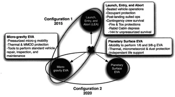
FIGURE 13: IMAGES OF THE ACES (LEFT), APOLLO EMU (CENTER), AND SHUTTLE/ISS EMU (RIGHT), IMAGES FROM N A SA4...-... 4 1 FIGURE 14: THE REQUIREMENTS OF THE THREE MISSION ENVIRONMENTS ARE COMPETING (ADAPTED FROM NASA)43 FIGURE 15: DEPICTION OF ESR1 ARCHITECTURE, CONFIGURATION 1 (LEFT) AND CONFIGURATION 2 (RIGHT); AREAS OF THE SAME COLOR ARE MODULAR BETWEEN THE SUITS, WITH THE ONLY DIFFERENCES BEING THE UPPER TORSO, VISORS, AND THERMAL AND MICROMETEORITE GARMENTS, IMAGE FROM NASA...46
FIGURE 16: EVA SYSTEM REFERENCE 2 (ESR2) COMPOSED OF CONFIGURATION 1 (LEFT) AND CONFIGURATION 2 (RIGHT), (N A SA )... 4 7 FIGURE 17: DIAGRAM OF RISK SHARING BASED ON CONTRACTUAL STRUCTURE ... 51
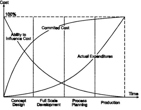
FIGURE 18: MODEL OF COMMITTED FUNDS AND THE ABILITY TO INFLUENCE COST IN A PROJECT'S LIFE CYCLE(SCHULZ,
CLAUSING, N EGELE, & FRICKE, 1999) ... 56
FIGURE 19: ORGANIZATIONAL STRUCTURE OF THE EVA SYSTEM PROJECT ... 61
FIGURE 20: INTEGRATION GROUPS AND THEIR INVOLVEMENT, IN WHICH DASHED LINES REPRESENT LINES OF COMMUNICATION AND SOLID LINES REPRESENT MANAGERIAL AUTHORITY ... 62
FIGURE 21: COST ESTIMATING METHODS AND TIME OF THEIR APPLICABILITY (2008 NASA COST ESTIMATING H A N D BO O K)...6 5 FIGURE 22: FINAL CONFIGURATION OF THE ISS SHOWING PARTNER CONTRIBUTIONS (NASA)...75
FIGURE 23: A DRAWING OF AN INTERNATIONAL STANDARD PAYLOAD RACK (ISPR) ... 78
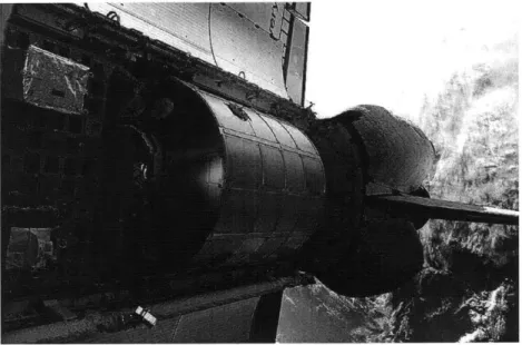
FIGURE 24: AN IMAGE OF THE MPLM INSIDE OF THE SPACE SHUTTLE'S PAYLOAD BAY ... 80
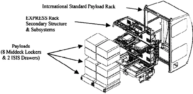
FIGURE 25: IMAGE OF THE EXPRESS RACK, DISPLAYING THE AVAILABLE VOLUME(SLEDD, 2000)...83
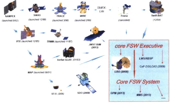
FIGURE 26: HERITAGE ANALYSIS REVEALED THE EVOLUTION OF FLIGHT SOFTWARE SYSTEM ARCHITECTURES OVER TIME (WILMOT, CORE FLIGHT SOFTWARE SYSTEM (CFS) PRESENTATION) ... 96
FIGURE 27: CFS ARCHITECTURE LAYERING, THE BLUE LAYERS INDICATE THE COMMON CORE, WHILE THE GREEN INDICATE THE CUSTOMIZABLE SECTIONS (ALTHOUGH THERE ARE SEVERAL COMMON SW APPLICATIONS). DIVERGENCE HAS OCCURRED, CAUSING THE DEVICE ABSTRACTION LAYER TO NO LONGER BE A PART OF THE CORE. (W ILM OT, 2008) ... 100
FIGURE 28: A DIAGRAM SHOWING THE CFS APPLICATIONS AND THE INTERACTIONS WITH THE MESSAGING MIDDLEWARE (WILMOT, CORE FLIGHT SOFTWARE SYSTEM (CFS) PRESENTATION) ... 102
FIGURE 29: INDEPENDENT DEVELOPMENT STREAM FOR THE CFS SYSTEM ... 110
FIGURE 30: THREE HIGH-LEVEL APPROACHES FOR THE MANAGEMENT OF COMMONALITY WITH THE EXTREMES OF NO COMMONALITY AND THE CREATION OF A COMMONALITY CULTURE ... 119
FIGURE 31: BENEFITS TO INDIVIDUAL SYSTEMS BASED ON ORDER OF CAPABILITY AND PRODUCTION VOLUME ... 133
FIGURE 32: DIAGRAM OUTLINES THE BEST ORDER OF DEVELOPMENT IN ORDER TO MAXIMIZE THE LIFE CYCLE COM M ONALITY BENEFITS... 134
FIGURE 33: CLASSIFICATION OF COMPONENTS WITHIN COMMON SYSTEMS...139
FIGURE 34: THE COST MODEL IS NOT A STAND-ALONE MODEL, BUT A METHOD OF UPDATING INDEPENDENT COST EST IM AT ES...1 4 0 FIGURE 35: ASSUMED TIMELINE OF DEVELOPMENT, PRODUCTION, AND OPERATIONS USED FOR THE DISCUSSION OF THE EFFECTS OF EACH COM MONALITY CLASS...142
FIGURE 36: RELATIVE LEARNING BENEFITS ON THE UNIT COST BETWEEN COMMON DEVELOPMENT AND INDEPENDENT DEVELOPMENT FOR PRODUCTION IN PARALLEL (TOP LEFT), 50% OFFSET (BOTTOM CENTER), AND SEQUENTIALLY (TOP RIGHT)...14 6 FIGURE 37: AVERAGE UNIT COST VS THE PRODUCTION RATE WITH ECONOMIES OF SCALE BENEFITS...147
FIGURE 38: ECONOMIES OF SCALE BENEFITS IN WHICH PRODUCTION IS 50% OFFSET ... 147
FIGURE 39: THE RELATIVE COST IMPACTS OF COMMONALITY ON EACH CLASS OF COMPONENTS ON THE NON-RECURRING COSTS AS A RESULT OF THE DESCRIBED BENEFITS AND PENALTIES ... 150
FIGURE 40: THE RELATIVE COST IMPACTS OF COMMONALITY ON EACH CLASS OF COMPONENTS ON RECURRING COSTS AS
A RESULT OF THE DESCRIBED BENEFITS AND PENALTIES ... 151
FIGURE 41: ASSUMED LIFE CYCLE TIMELINE FOR THE CSSS EXAMPLE ... 154
FIGURE 42: SAND CHARTS OF THE DEVELOPMENT, PRODUCTION, AND OPERATIONS COSTS WITH INDEPENDENT DEVELOPMENT (TOP) AND COMMON DEVELOPMENT (BOTTOM) ... 156
FIGURE 43: LIFE CYCLE COST FOR INDEPENDENT DEVELOPMENT, COMMON DEVELOPMENT, AND THE DIFFERENCE BETW EEN THE TW O DEVELOPMENT ESTIMATES ... 157
FIGURE 44: DECISION TREE DEVELOPED FOR THE CSSS OPTIONS-BASED ANALYSIS... 163
FIGURE 45: DESCRIPTION OF PROBABILITIES CHOSEN FOR THE DISCRETE DECISION TREE ... 165
FIGURE 46: CDFS FOR EACH OF THE CHOICES AND THE EXPECTED COSTS OF EACH OPTION ... 166
FIGURE 47: DEVELOPMENT STRATEGY BASED ON DECISION TREE ANALYSIS ... 167
Table of Tables
TABLE 1: SUMMARIZATION OF THE VARIOUS LEVELS OF COMMONALITY MANAGEMENT, AS DEFINED BY BOAS (2008)
... 2 8
TABLE 2: AWARD FEE EVALUATION CRITERIA AND RESPECTIVE WEIGHTS (NASA, ESPO, 2007)...52
TABLE 3: UTILIZATION RIGHTS AS OUTLINED IN THE IGA AND MOUS ... 76
TABLE 4: SUMMARY TABLE OF LIFE CYCLE OFFSETS AND DIVERGENCE IN THE NASA CASE STUDIES...118
TABLE 5: SUMMARY OF EACH OF THE MANAGEMENT APPROACHES OBSERVED IN THE NASA CASE STUDIES...122
TABLE 6: SUMMARY OF THE MANAGEMENT FINDINGS FROM THE THREE NASA CASE STUDIES AND THE SEVEN INDUSTRY CASE STUDIES ... 136
TABLE 7: LIST OF EQUATIONS USED TO QUANTIFY THE RELATIVE SIZE OF EACH OF THE FIVE COMMONALITY CLASSES ... 1 4 2 TABLE 8: CHART DESCRIBING THE FACTORS THAT INFLUENCE THE COST BASIS FOR EACH PHASE OF THE LIFE CYCLE FOR EACH SYSTEM; A '1' INDICATES THAT THE COST BASIS IS UNAFFECTED WHILE A 'O INDICATES THAT THE BASIS IS NOT INCLUDED IN THE COMMON SYSTEM COST ESTIMATE ... 143
TABLE 9: TABLE REPRESENTING THE FACTORS THAT INFLUENCE THE COST BASIS FOR CLASS 2... 144
TABLE 10: FACTORS THAT AFFECT THE COST OF CLASS 3 COMPONENTS... 148
TABLE 11: FACTORS THAT AFFECT THE COST BASIS FOR CLASS 4 COMPONENTS... 149
TABLE 12: FACTORS THAT AFFECT THE COST BASIS FOR CLASS 5 COMPONENTS, IN WHICH A '0' INDICATES THAT THE BASIS IS NOT PART OF THE COST ESTIMATE AND A '1' INDICATES THAT THE BASIS IS NOT AFFECTED BY THE BENEFITS AND PENALTIES OF COMMONALITY...149
TABLE 13: SUMMARY OF EACH OF THE EFFECTS OF COMMONALITY ON THE SYSTEM BASED ON THE DEVELOPMENT PH A SE ... 1 5 0 TABLE 14: EQUATIONS USED TO ANALYZE OPPORTUNITIES FOR COMMONALITY, INCLUDING THE COST BASIS AND THE SYSTEM M ULTIPLIERS ... 15 1 TABLE 15: MULTIPLIER EQUATIONS USED IN THE ECONOMIC MODEL TO INCORPORATE THE BENEFITS AND PENALTIES OF COMMONALITY FOR THE PRODUCTION PORTION OF THE SYSTEM ... 152
TABLE 16: MULTIPLIER EQUATIONS USED IN THE ECONOMIC MODEL TO INCORPORATE THE BENEFITS AND PENALTIES OF COMMONALITY FOR THE OPERATIONS PORTION OF THE SYSTEM ... 152
TABLE 17: PREVIOUSLY UNDEFINED FACTORS REQUIRED FOR THE QUANTITATIVE ANALYSIS OF THE SYSTEMS...152
TABLE 18: SUMMARY OF THE SYSTEM'S DEVELOPMENT, PRODUCTION, AND OPERATIONS TIMELINE FOR THE CSSS EXA M PLE ... 1 5 4 TABLE 19: SUMMARY OF EACH OF THE ASSUMED FACTORS IN THE ANALYSIS...155
TABLE 20: RESULTS FROM THE ECONOMIC COST MODEL, PRICES IN $ MILLIONS...156
TABLE 21: SUMMARY OF THE HOW EACH BENEFIT AND PENALTY FACTOR CONSIDERED IN THE MODEL AFFECTS THE RESULTANT TOTAL LIFE CYCLE COST ESTIMATE ... 158
TABLE 22: THE EXPECTED VALUES OF THE SYSTEM WITH VARYING LEVELS OF DISCOUNT...159
TABLE 23: OBJECTIVE OF ANALYSIS COMPARED WITH THE DIFFERENT VALUATION METHODS (DE NEUFVILLE)...161
TABLE 24: COMPARISON OF THE TYPE OF UNCERTAINTY IN THE SYSTEM TO THE OBJECTIVE OF THE ANALYSIS (DE N EU FV ILLE)...1 6 2 TABLE 25: ASSUMED PROBABILITIES OF DISCRETE EVENTS USED FOR THE CSSS ANALYSIS... 164
TABLE 26: VALUES FOR THE EXPECTED COST OF EACH CDF CURVE ... 166
TABLE 27: COMPARISON OF THE EXPECTED COST OF EACH DEVELOPMENT APPROACH ... 168
I
.
Introduction
The creation of a large engineering system requires decision makers to prioritize between competing goals. These goals include, but are not necessarily limited to, cost, technical performance, schedule, and risk. The listed goals are competing because they cannot all be optimized at the same time. The most common representations of this trade are the Triple Constraint Concept (NASA Cost Estimating Handbook, 2008), and the Iron
Triangle of Management. Applying commonality to a system offers one method of trading these goals in order to offer a project or system-wide benefit; often involving a trade in performance to offer either schedule, risk, or cost benefits.
Commonality can be defined as the sharing of assets such as components, designs, processes, technologies, interfaces, and/or infrastructure across systems (Boas, 2008).
Commonality is not the only method of improving a system, but through commonality NASA has the opportunity to develop, produce, and operate systems more efficiently.
The specific benefits from the application of commonality as they apply to each of the life cycle phases are discussed in section 2.4 Benefits and Penalties.
Commonality is not a new concept, but has been implemented by industry and the government for many years as seen in power tools, printers, cars, airplanes, and satellites (Boas, 2008). For example, the Department of Defense (DoD) recently implemented commonality in the design of a new fighter jet, the Joint Strike Fighter (JSF) or F-35. The JSF was developed for use by the Air Force, Navy, and Marines, each of which have different requirements for their fighters, as seen in the variants in Figure 1. Application of commonality in the JSF project allowed the government to procure three aircraft variants for the price of 1.8 aircrafts (Boas, 2008).
Conventional Take-Off and Landing (CTOL) F-36A Uft Fan 34W" Short Take-Off q Vertical Landing (STOVL) F-36B
Figure 1: Joint Strike Fighter design variances, (from (Boas, 2008))
Commonality is created between systems by the reuse of assets from a previous system. The reuse of assets can be conducted in two ways: the asset can be reused reactively, without prior planning; or the asset can be developed in the first system with the intent that it becomes common to future systems, i.e. forward commonality. In order for commonality to have substantial, widespread benefits to a system, forward commonality should be actively sought out and applied. However, the benefits gained from
commonality greatly depend on how commonality is managed.
The goal of this research is to observe how commonality is managed and applied within NASA systems and to identify the best practices and key challenges associated with the management of commonality. To that end, three case studies were conducted of past and present NASA systems: the Constellation Space Suit System (CSSS), the International Standard Payload Rack (ISPR), and the Core Flight-Software System (CFS). Each of the case studies was chosen because they offer a diverse view into the management of commonality by differing in the program in which the system is operated, the type of system that was developed, the organizational structure, and the method used to develop the system. However, the theoretical most difficult management case was not observed in
the NASA case studies, in which commonality must be managed between two contractors. The remainder of this thesis is organized as follows:
Carrier Variant (CV) F-35C
Chapter 2 presents much of the current knowledge on commonality, including a discussion of the challenges for application, management approaches used, and the benefits and penalties of commonality to a system.
Chapter 3 then presents the first of the three case studies, on the Constellation Space Suit System (CSSS). This chapter includes a background to the Constellation Program, a discussion of the architectural requirements, the development process used, and finally observations on the system challenges and the management of commonality.
Chapter 4 follows a similar format for the second of the three case studies, on the payload management system with a focus on the International Standard Payload Rack (ISPR). The chapter contains a discussion of the background of the system, the original architecture of the system, the evolution of the architecture, and observations on the challenges and management methods used in this case.
Chapter 5 then presents the findings from the third case study, on the Core
Flight-Software System (CFS). The chapter contains a background to the system, information on the architecture of the system, the evolution of the system, and finally observations on how commonality was managed within the system.
Chapter 6 presents the cross-case analysis and final conclusions from all of the case studies. This chapter also presents guidance for NASA managers on how to best manage commonality; including different approaches for applying commonality and specific management methods that should be used based on the type of system, the development method, and the organizational structure of the particular system.
Commonality does not always benefit a system, but often implies a trade between competing goals. Therefore, opportunities for commonality should be evaluated to determine the benefits and penalties. In the NASA and industry case studies, the evaluation process was predominately either not conducted or limited to a qualitative analysis. Chapter 7 presents the method and application of two quantitative methods of estimating life cycle costs of common systems: a deterministic economic cost model and an economic cost model that evaluates commonality as a Real Option. Evaluating
commonality as a real option allows managers to consider uncertainty in the system and the value of flexibility in order to develop the optimal development strategy.
Finally, Chapter 8 summarizes the contributions of the thesis in order to create a better understanding of the management of commonality. Recommendations are made for future research.
2.
Introductory Concepts and Background
Literature
This chapter presents the introductory concepts and background literature that serves as the basis for the NASA case studies. The three case studies of NASA systems were intended to build on the seven industry case studies previously conducted by Boas (2008), as a result this chapter discusses many of the findings from the seven industry case studies, as well as findings from other literature on commonality management. The first section, Types of Commonality, more accurately defines the concepts of
commonality that will be researched in this thesis. Next, two trends that were identified in the industry case studies, divergence and life cycle offsets, are discussed. The discussion includes the effects that these trends have on the management of commonality in practice. Next, the critical management tasks are explained along with observations from the
industry case studies on the different approaches to manage these tasks. Finally, the benefits and penalties of commonality are discussed as they relate to each phase of a system's life cycle.
2.1 Types of Commonality
Commonality can be defined as the sharing of assets such as components, designs, processes, technologies, interfaces, and/or infrastructure across systems (Boas, 2008). While the definition of commonality remains constant there are two distinctly different methods of applying commonality between systems: reactive reuse and forward
commonality.
Reactive Reuse
Reactive reuse is the case in which a system reuses a component that was designed solely for a past system by integrating the component into a new system. Reactive reuse is not associated with any forward planning or coordination, and as a result can be limited in
scope compared to forward commonality. However, reactive reuse is a common practice with significant benefits.
Forward Commonality
Forward commonality is the case in which opportunities for commonality are actively sought out and developed in the first system with the intention that they become common and are reused in the future system. Forward commonality is referred to under other names in other studies, such as the development of product families and design for reuse. This study will primarily focus on observations and good practices for the management of forward commonality because it allows for the maximum benefits from commonality to be obtained.
There are additional terms that are worth defining at this time because they are related to aspects of forward commonality and were observed in the NASA case studies:
modularity and standardization. Modularity is defined by Fricke and Schulze (2005) to be a principle that aims at "building a system architecture that clusters the system's
functions into various modules while minimizing the coupling among the modules (loose coupling) and maximizing the cohesion within the modules (strong coupling)."
Modularity is developed for several reasons, but one of the benefits is that it makes a system flexible by allowing modules to be swapped out or allowing the same module to be shared by multiple systems, as seen in Figure 2. Modularity and commonality are closely related because all types of modularity require at minimum a common interface and often result in additional commonality. Component sharing modularity was utilized in the Constellation Space Suit System (CSSS) case study in order to obtain life cycle cost benefits and to reduce the launch mass of the system. Component-swapping
modularity was utilized in the International Standard Payload Rack (ISPR) case study to offer additional flexibility.
ConMonent swapping modulaity
Figure 2: Two of the six types of modularity (altered from (Fricke & Schulz, 2005))
Standardization is the creation of some degree of similarity or commonality by an authority or general consent. Standardization in all cases creates some degree of commonality and is referred to in some cases, including NASA documents,
synonymously with commonality. However, standardization is often implemented at lower levels of the system, such as the component or interface level, and predominately benefits production and operations. Standardization can be a useful method of applying
commonality between peer organizations in which no central authority exists to coordinate or manage designs. Standardization was used to apply commonality across systems in both the CSSS and ISPR case studies.
2.2 Trends in Commonality
Divergence and life cycle offsets were observed in each of the seven industry case studies and have been shown to dramatically impact the management of systems. Therefore, the first goal of the NASA case studies is to determine whether or not these trends also exist in NASA systems.
Divergence
Industry case studies conducted by Boas (2008) showed that commonality consistently decreased or diverged from what was originally planned. The trend that was commonly seen in the industry case studies was an increase in the amount of intended commonality during the planning phase, but a consistent decrease in commonality as development progressed, depicted by Figure 3.
C Divergence
0
E E
Y 'time
Planning Product Lifecycle
Figure 3: Divergence in a system's life cycle
Commonality should not be the final goal of a system because commonality does not always benefit a system. Instead, the goal should be to obtain the maximum benefit from commonality. Therefore, divergence, or a decrease in commonality, can occur to either benefit or penalize a system. Acceptable factors cause divergence in order to improve the system, while unacceptable factors cause divergence while penalizing the system. The causes for divergence as observed in the seven industry case studies (Boas, 2008) include:
- Acceptable factors:
" Market change - Demand for the common item drops, requiring developers to seek unique. solutions; change in requirements
o Technology - New technology has become available that can improve the product if divergence occurs; technology has become obsolete
o Learning - Learning in development may show that a unique solution is better than the already developed common solution because of technical factors or economic factors
"Unacceptable factors:
o Poor management or lack of coordination o Intentional pursuit of uniqueness
Life Cycle Offsets
Much of the literature and scholarship on commonality assumes that the development of common systems is conducted in a parallel and coordinated manner. However, seven industry case studies, previously conducted by Boas (2008), found that in most cases life cycle offsets exist. Meaning that while planning for the two systems may be conducted at the same time, the development, production, and operations of the common systems are offset in time, as seen in Figure 4.
Life
Cyclt Development B Prdcin and Operations B
Development A Production and Operations A Time
Figure 4: Life cycle offsets often occur between two common systems
A few factors were identified by Boas (2008) to have the tendency to create life cycle offsets:
e Market factors -testing market with first variant; or different dates of need e Technology factors -technology capability development; and learning from
earlier products
e Organizational factors -organizational focus on a product; and human resource
constraints
- Financial factors -total program cost; cash flow management; and budgetary restrictions
Commonality in Practice
Life cycle offsets and divergence have several impacts on the management of
commonality. This section discusses the effects that both divergence and life cycle offsets have on the management of common systems.
Offsets create a necessary decision at the time of development: to either develop with intended commonality or to develop independently
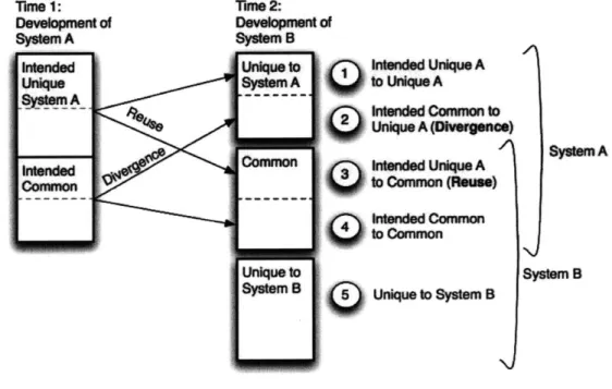
Life cycle offsets between systems result in decisions that must be made at the time that the first system is developed: components can be developed with the intention that they become unique, or with the intention that they become common, as indicated at Time 1 in Figure 5. However, divergence and reuse often occur. Therefore, at the time that the
future system is developed, common components either become common as planned or unique to the first system because of divergence, indicated by classes 2 and 4 respectively
in Figure 5. Components that were developed with the intent to be unique to the first system are either reactively reused and become common or remain unique to the first system, as indicated by classes 1 and 3 respectively in Figure 5. Based on this framework developed by Boas (2008), there are five classifications of components between common systems. The five commonality classes form the basis for the economic models discussed in Chapter 7.
Tie 1: Tn*2:
Development of Developmentof
System A System a
intened Une to Intened Unique A
Unique SystenA to Unkque A
StmA ---- --- Intended Common to
Unique A (Divergene)
System A
nded common Intended UnIque A
Common to Common (neuse)
noended Common
to Common
Unique to System B
SystemB Unique to System B
Figure 5: Framework for classifying commonality, which takes into account life cycle offsets, divergence, and reactive reuse (based on (Boas, 2008))
Offsets cause an up-front development penalty
Developing components with the intent that they become common with future systems involves developing the components to meet additional requirements; the additional requirements result in additional development costs. In the benefits and penalties sections the up-front penalty is described as the cost of common development.
Existence of offsets cause benefits to be offset to future systems
While the first system inherits an up-front development penalty, most of the development benefits are passed on to later variants in the form of reduced development work. The
later variants do, however, inherit a development cost associated with the integration of the common components into the system, i.e. the integration penalty.
Total benefits from commonality decrease as a result of offsets
-Offsets in production and operations decrease the potential benefits obtainable from commonality, including economies ofscale (production), capability overlap (operations), and learning (production and operations). Each of these factors are discussed in more detail in Section 2.4 and Chapter 7.
Offsets cause future variants to be uncertain and often unrepresented at the time that the first system is developed
At the time that the first system is being developed, the later variants are uncertain. As a result, design decisions are weighted towards the current system. This issue is
compounded by the fact that future variants are also often unrepresented at the time that decisions are made.
Offsets increase the likelihood that divergence will occur
Life cycle offsets increase the likelihood that divergence will occur because there is a greater likelihood that the market or technologies will change as more time passes.
2.3 Management
In the industry case studies conducted by Boas (2008), the management approach and methods used for the application of commonality was found to be a critical factor for
success. This section begins by discussing the critical tasks associated with the
management of commonality, which include: managing the identification of opportunities for commonality, evaluating opportunities, and implementing beneficial opportunities for commonality. Next, the management approaches observed in the industry case studies are discussed.
Management Tasks
In conducting the NASA case studies, it was observed that in order for commonality to be successfully applied to a system, the opportunity for commonality must be: (1)
technically feasible, (2) beneficial, and (3) implemented successfully. Therefore, in order for commonality to be managed successfully there are also three critical management tasks:
1. The management of the identification of opportunities
2. Evaluation of opportunities to determine whether or not each opportunity is beneficial
3. Implementation of the opportunities that are deemed beneficial
Each of these management tasks presents challenges that must be overcome. The first task is to manage the identification of opportunities. For the first task, the challenge lies in the fact that forward commonality will not be created by chance, but must be actively sought out and identified. This study will not focus on the technical feasibility of
commonality, but instead on how the identification of opportunities is managed. The second task is to evaluate opportunities for commonality to determine the benefits and penalties. Commonality will not benefit the system if it is blindly implemented wherever technically feasible. Instead, each opportunity should be evaluated to determine the benefits and penalties that it will have on the system. Commonality has many benefits and penalties that affect the system in different and sometimes unexpected ways, making the evaluation of opportunities difficult. The benefits and penalties are examined in detail in Section 2.4, Benefits and Penalties. In addition, the work conducted to improve the evaluation of opportunities for commonality is discussed in Chapter 7.
The last task is to implement opportunities for commonality that are deemed beneficial. Opportunities for commonality are often not implemented as planned, because there are several challenges, including life cycle offsets and divergence.
The management methods used in each of the three NASA case studies is discussed at the end of each chapter in relation to each of the management tasks identified in this section. The final cross-case analysis discussing each of the management methods is discussed in Chapter 6.
Management Approaches
In Boas' study of industry applications of commonality (Boas, 2008), three levels of commonality management were observed: (1) informal reactive reuse, (2) the development of common building blocks, and (3) a formalized process for the
widespread application of commonality. Each of the observed levels are described and expanded on below. The management approaches observed in the three NASA case studies is discussed in Chapter 6.
Reactive Reuse Approach
There are a few aspects of each of these levels that distinguish them from each other. In the case studies conducted by Boas the most common level of commonality management observed was the informal reactive reuse of components. This approach is described by a single-product culture in which the focus of development is on the optimization of a
single product at a time. Instead of developing forward commonality, these organizations often develop independently and reactively reuse assets from previous systems as they see fit. The most beneficial form of reactive reuse involved the use of the previous system as the baseline for future development. In addition, little to no formal ownership of
commonality and no processes to control commonality and changes to the system were observed.
Common Building Block Approach
The other two levels of commonality management were observed less often than the first and both of these levels applied aspects of forward commonality. The second level of
commonality management still predominately involves single-product cultures, however items of value were developed separately as common building blocks to be used on future variants. The common building blocks were often managed outside of the control of any individual project in a parallel development stream.
Widespread Forward Commonality Approach
The third level of commonality management that was observed is described as the creation of a formal process to identify, evaluate, and implement widespread
commonality. At this level, widespread forward commonality is actively sought out. Common components are specifically identified as common and there is ownership for the common components. There are also formal methods in place to control changes to the system. Boas describes the ultimate approach for commonality management as the
development of a commonality culture. The commonality culture is the approach in which commonality has been so engrained in the culture that a formalized process become less important. The commonality culture is viewed as the ideal case and an
extension of the widespread application of forward commonality by extensive management support.
In each of the levels of commonality management described, the development of control processes and ownership of commonality were consistently associated with the successful management and application of commonality. Each of the observed methods and aspects of management are highlighted in Table 1.
Table 1: Summarization of the various levels of commonality management, as defined by Boas (2008)
Informal Reactive Reuse Common Building Block Widespread Formal
___________Process
Culture Single product culture Single product culture w/ a Common product culture
___________few exceptions
Independent development Formal process to identify,
Development Previous product is starting with effort placed on evaluate, and implement
Process point for future variants commonality for a few high- forward commonality
value components
Ownership of No formal ownership of Formal ownership and Formal ownership and Commonality commonality tracking of a few common tracking of commonality
building blocks
Forward commonality may Common building blocks At times commonality was
Other have been considered in were developed implemented purely for
Comments some contexts, but by far independent of a particular commonality sake, without the dominant effort was on program in a few cases proper evaluation
a single product I techniques
2.4 Benefits and Penalties
Current literature on commonality predominately focuses on the benefits and penalties to the development and production phases of a system's life cycle. However, in order to more completely determine whether commonality should be implemented within a system, the effects of the benefits and penalties on all phases of the life cycle should be evaluated. The benefits and penalties are examined below as they apply to each phase of a system's life cycle.
In this section, it will be assumed that life cycle offsets exist between the two common systems. To simplify the discussion of the benefits and penalties, the first system developed will be referred to as system A, while the systems that are developed in the future are referred to as system B, although there may be a collection of future variants. Chapter 7 expands on these benefits and penalties by integrating them into an economic model to evaluate the opportunities for commonality.
2.4.1
Development
The development of common systems can either be conducted through forward
commonality or reactive reuse. This section will describe some of the monetary and non-monetary benefits and penalties of commonality, and how they impact the system. Figure
6 demonstrates the monetary benefits and penalties on the development cost of system A and system B.
Benefits
- Decrease in development cost and time - The reuse of design and development work from system A, through either forward commonality or reactive reuse, decreases the amount of work that must be conducted for system B. The decrease in development work can take the form of lower costs or less time to market. The amount of time to market is an extremely important factor when competing with other firms and developers for market share (Robertson & Ulrich, 1998). This is a benefit to system B in both reuse and forward commonality.
e Decrease in future system development risk -Developing a future common
variant requires a lower development investment, resulting in less development risk for system B. The lower development risk allows managers to develop a new common variant that may be considered to expensive or risky without the ability to use the common components (Gonzalez-Zugasti, Otto, & Whitcomb, 2007). The lower development risk also allows developers to create a family of products with greater system variability to meet the demands of more niche markets. This is a benefit to system B in both reuse and forward commonality.
Penalties
e Cost of Common Development - In order to develop forward commonality
between system A and system B, additional development work must be conducted at the time that system A is developed. The increased development work is called the cost of common development and results because system A must be designed to meet the requirements of future systems in addition to those of system A. This is a penalty on system A in the case of forward commonality.
e Integration Penalty - When reusing development work from previous systems, the development cost associated with the common components is not completely eliminated because the common components must be integrated into system B.
The required work, referred to as the integration penalty, often takes the form of additional development and testing. This is a penalty on system B in both reuse and forward commonality.
Development Cost vs Degree of Commonality
System B System A 0% 50% 100% % Commonality
Figure 6: The categorization of development costs for system A and system B, as the percentage of commonality increases between the systems. The cost impact is based on the factors described above,
including: decreased development work, cost of common development, and the integration penalty.
2.4.2
Production
In the following discussion of the effects of commonality, it is assumed that production costs are predominately composed of variable recurring costs. Figure 7 summarizes the economic effects of the benefits and penalties of commonality that are discussed in this section.
Benefits
e Economies of scale -Common components that are manufactured for several
systems will be produced or procured in larger volumes than if commonality was not employed. Commonality causes firms to procure or produce larger volumes of the common components and, as a result, spread the fixed recurring costs across a greater volume of components, resulting in lower cost per item. The decreased
... ...
cost per item is referred to as economies ofscale (de Neufville, 1990). In the case of overlapped production, this benefit will affect the materials portion of the costs for both systems A and B in reuse and forward commonality.
Accelerated learning curve - A learning curve refers to the fact that production is easier, cheaper, and faster the second time a product is produced. This holds true for each additional product until production reaches a limit in efficiency. An increase in the production quantity of common components leads to an
accelerated learning curve (Robertson & Ulrich, 1998). In overlapped production, this benefits the labor portion of systems A and B equally, but as the offset
increases the benefits to labor will be shifted to system B. The benefits are obtained in both reuse and forward commonality.
Penalties
e Excess capability penalty -Common components are often more complex than
independently developed components because they are designed to meet
additional requirements. The added complexity makes production more expensive compared to independent components. This penalty, referred to as the excess capability penalty, affects both systems but it may not affect them equally. In general, this penalty will affect system B in reuse and systems A and B in forward commonality.
Production Cost vs Degree of Commonality System V8 0 System A 0% 50% 100% % Commonality
Figure 7: Production cost vs. percentage of commonality, based on learning curve benefits, economies
ofscale, and excess capability penalty; the plot shows that system A will likely receive marginal
benefits, while system B receives greater benefits
2.4.3
Operations
Operations costs are composed of both fixed recurring and variable recurring costs. Fixed recurring costs are incurred whether a system is operated or not and is independent of the number of operations that occur. Variable recurring costs are the marginal costs per operation. Fixed and variable recurring costs are each benefitted in different ways: by a
capability overlap and an accelerated learning curve, respectively.
In order to maintain the capability to operate a component there is a fixed recurring cost. If the component is common between multiple systems, the fixed recurring cost is shared between the systems, resulting in a benefit from the capability overlap to both systems or the later system, depending on the accounting method chosen.
The accelerated learning curve refers to the fact that completing a task is easier, cheaper, and faster the second time the task is conducted. Developing components and processes with commonality results in fewer unique components, and increased frequency in which the common component or process is operated. Commonality thus creates an accelerated learning curve in variable recurring costs as a result of the increased operation frequency.
The accelerated learning curve benefits variable recurring costs for systems A and B equally if operated in parallel, but as the offset increases the benefits will be shifted to system B. The benefits are obtained in both reuse and forward commonality.
The benefits to commonality, below, will be described as it applies to fixed recurring costs as a capability overlap, or to variable recurring costs as an acceleration of learning. Figure 8 represents the economic impacts of commonality on the operations phase for both systems.
Benefits
- Decreased sustaining engineering - Utilizing commonality will decrease the number of unique technologies and components, which in turn decreases the
amount of required sustaining engineering. Sustaining engineering is the continued engineering and technical support of hardware that is in operation. NASA maintains technical expertise on hardware that is in operation in case that
expertise is needed during an operation. If a common component or system is operated more frequently because it is used on multiple systems, the fixed
recurring costs are not duplicated, but decrease because of the capability overlap. This is a benefit to both systems A and B, with an overlap in operations for both reuse and forward commonality.
- Decreased logistics costs - Logistics costs are the costs associated with storing, moving, maintaining, and securing hardware. Fewer unique components lead to smaller required inventories and lower logistics cost (Robertson & Ulrich, 1998) (Crites & Tremblay, 1989). The decrease in logistics costs results in a benefits to operations fixed recurring costs in the form of a capability overlap during years of parallel operations and to variable recurring costs from accelerated learning. This is a benefit to both systems A and B for reuse and forward commonality.
o Decreased sparing requirements - Fewer unique components lead to fewer on-orbit spares required to maintain a constant risk profile (Siddiqi & de Weck, 2007)(Crites & Tremblay, 1989).
* Decreased training costs - Creating common components decreases the number of unique components, which in turn reduces the training infrastructure and the training requirements for crewmembers, support, and training personnel (Coan & Bell, 2006)(Crites & Tremblay, 1989). The decrease in training costs results in a benefit to fixed recurring operations costs in the form of a capability overlap
during years of parallel operations and to variable recurring costs from the accelerated learning. This is a benefit to both systems A and B for reuse and
forward commonality.
* Decreased operations risk -Reusing space proven equipment increases the confidence in the equipment and reduces the risk of equipment failure (Gonzalez-Zugasti, Otto, & Baker, 2000). Additionally, common operation interfaces reduce the complexity of operations, which also reduces risk of operator error (Coan & Bell, 2006). It is important to increase the ease of operations for human space
flight because crewmembers are required to work in hostile and stressful
situations. Operations within the aerospace industry in particular, are inherently risky because they deal with relatively new technologies that cannot easily be tested on Earth. Having space proven equipment greatly reduces the risk of operations. In fact, private launch companies must reuse a certain percentage of
components in order to obtain insurance on launch vehicles and cargo.
Penalties
* Excess capability penalty -Common components are often more complex than independently designed components because they are designed to meet additional requirements. The added complexity makes operations more complex and
expensive compared to independent components. This penalty, referred to as the excess capability penalty, affects fixed and variable recurring costs of both
systems, but it may not affect them equally. In general, this penalty will affect system B in reuse, and systems A and B in forward commonality.
e Decreased performance - The application of commonality often includes a
performance penalty because the component or system is less optimized for a particular operation.
Operations Cost vs Degree of Commonality
50% % Commonality System B System A 100%
Figure 8: Operations cost vs. percentage of commonality. Benefits to fixed recurring costs occur only when the systems are operated at the same time. The chart shows all of the fixed recurring cost
benefits accruing on system B, but the benefits can be shared by both systems, based on the accounting approach chosen.
2.5 Conclusion
This chapter presented the relevant introductory concepts and background on the management of commonality. The information presented, forms the basis of knowledge for the remainder of the thesis. The chapter includes a discussion of trends such as divergence and life cycle offsets, and how these trends affect the management of
commonality, including a framework to classify the assets of a common system. Also, the chapter includes a description of the critical management tasks required to successfully manage forward commonality and the management approaches observed in the industry case studies. Finally, the chapter contains a detailed description of the benefits and penalties of commonality as described in literature.
3.
Constellation Space Suit System
The first case study was conducted on the Constellation Space Suit System (CSSS). Each of the case studies was chosen because it offered a diverse environment in which
commonality must be managed. The CSSS was chosen because it offers an example of (1) commonality applied within a complex system primarily composed of hardware, (2) it is part of the more recent Constellation Program, and (3) because development for the CSSS was contracted out by NASA.
The EVA System Project Office (ESPO) is the organization tasked to create the CSSS. They are specifically tasked to create a suit system that can protect the crewmember during (1) Launch, Entry, and Abort (LEA), (2) microgravity EVAs, and (3) planetary surface EVAs. Each of the listed mission environments creates competing requirements, prohibiting a single suit system. Despite the competing requirements, ESPO is working to minimize life cycle costs and the launch mass by creating a highly common and modular suit system. The details of the architecture requirements and resultant requirements are discussed in section 3.2, Constellation Space Suit Systems.
The primary method used by ESPO to manage commonality is to baseline all assets that could conceivably become common as common between the two suits and to
subsequently control divergence to ensure that when divergence occurs it is for an acceptable reason. The detailed observations related to the management methods used, are discussed in section 3.3, Observations.
3.1 Background
In 2004, President George W. Bush gave NASA a new Vision for Space Exploration (VSE) that set NASA on a path to place people on the moon by 2020 and on Mars by the following decade (Bush, 2004). The new vision created a need for a completely new space transportation system because the current system, the Space Shuttle, can only be
used for missions to Low-Earth Orbit (LEO). The new program was named the Constellation Program. This section outlines the architecture of the Constellation Program as it existed when the CSSS case study was conducted.
The architecture of the Constellation Program is divided into three major phases: (1) the initial capability (IC) phase, (2) the lunar capability phase, and (3) the Mars capability phase. Figure 9 shows the projects required for each of the phases. The initial capability phase, scheduled for launch by 2015, will involve launching up to four crewmembers into LEO in Orion using the Ares I launch vehicle. The IC phase requires that crewmembers are able to work efficiently in launch, entry, and abort (LEA) environments. The suits are required to return any consumables that it receives for ventilation, cooling, and breathing from the vehicle back to the vehicle, offering a highly closed-loop system.
08010111121131141151 l61171l8119120121122123124125126127128129130
Orion - Development Orion - Production and Operations
Ares
I
Ares IEVA Systems EVA Systems
Altair - Development Aftair - Production and Operations
Ares V Ares V
Lunar EVA Systems Lunar EVA Sy stm
Lunar Surface Systems Lunar Surface Systems Martian EVA System - Development _ Lfe cycle
0.a Martian Surface Systems Mars Initial Start Martian Transportation Systems
Date -TBD
Figure 9: The Constellation Program schedule for the development (shown in red) and production and operations (shown in blue) for each phase (the development start date of the Mars Capability
phase is not set, but operations are base-lined for 2030)
The lunar surface capability phase, scheduled for launch by 2020, will similarly launch the crew into LEO in Orion using Ares I, as seen in Figure 10. However, once in orbit the crew will dock with the lunar lander, named Altair, and the Earth Departure Stage (EDS). Altair and the EDS will be launched into orbit using the Ares V launch vehicle. The EDS
will then be used to accelerate Orion and Altair towards the Moon. The crew will transfer to Altair, separate from Orion, and descend to the lunar surface. For extended stays, habitation modules will meet the crew on the lunar surface. Once tasks are completed, the lunar ascent module will return astronauts to the orbiting Orion vehicle. Orion will then be used to transfer the crewmembers back to Earth. The lunar capability phase requires
the crew to operate during LEA, micro-gravity extravehicular activities (EVA), and planetary surface EVA mission environments.
rc'; effm'x Lt~
Ares V Ares I a
Figure 10: Constellation Program lunar capability phase architecture sequence, altered from: (ESAS, 2005)
The Mars capability phase was outlined in the Exploration Systems Architecture Study (ESAS) (Figure 11). Martian capability will additionally require the creation of a Mars transportation vehicle that will transfer the crew to and from Mars for a 500-day stay on the surface. The Mars capability phase requires that the EVA System support crew operations during LEA, micro-gravity EVA, and planetary surface EVA mission environments.
Prd*,epiced Crew Lans
S
aeHabia D rtlanm sAscent
Deorbt A roastry
Ae tyn d asd
/
d o Mars AscentMar Ortstage s eod
Aarocapture Pra. .V MVRemm s
de ployed iM Oritt
Fligt Flight g
Earth -Mars Eart Mmals Mars Eafth
Transposition yT Ryby
Earth Orbit a Docking
NT NO P NTP CEV 4 L
Stage Stage stagDo
Sorace Ma T Ln
Mabit
LdLad
I I
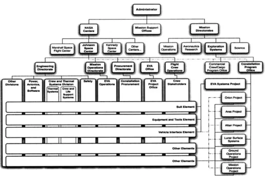
The Constellation Program is divided into seven projects based on the program's architecture. Each project is led by a project manager and supported by a number of groups, such as Systems Engineering and Integration (SE&I). Each project is then sub-divided into elements; in the case of the EVA Systems Project Office (ESPO) they are: the suit element, the equipment and tools element, and the Vehicle Interface Element
(VIE). Figure 12 shows the Constellation Program's hierarchy with regards to the EVA System Project.
Level 11Constellation
L Equiment m Oice
Leve II
Figure 12: Constellation Program and EVA System project organization
3.2 Constellation Space Suit Systems
In addition to the new space transportation system, the Constellation Program also
requires a new EVA system because the space suits currently in operation do not meet the requirements of the Constellation Program. The following section, Architecture
Requirements, describes the technical requirements of the Constellation Program that affected the EVA System and how these requirements have influenced the CSSS architecture. The most significant impact is seen in the required operational
environments: launch, entry, and abort, microgravity EVA, and planetary surface EVA. The resultant CSSS architecture will be composed of two common suit configurations. Details about the development and design of the architecture are discussed in section 3.2.2, Architecture Development. When the case study was conducted the acquisition process was in progress. Aspects of the acquisition that apply to the management of commonality are discussed in section 3.2.3.