AN APPROACH TO SOURCING OPTIMIZATION AT A HIGH VOLUME SOFT
DRINK MANUFACTURER
By
Sandeep Khattar
B.S.E. Mechanical Engineering, University of Michigan (2000)
Submitted to the Sloan School of Management and the Department of Mechanical Engineering
in Partial Fulfillment of the Requirements for the Degrees of
Master of Business Administration
and
Master of Science in Mechanical Engineering
In Conjunction with the Leaders for Manufacturing Program at the
Massachusetts Institute of Technology
June 2006
0 Massachusetts Institute of Technology, 2006.
All rights reserved.
Signature of Author
Sloan School of Management
Department of Mechanical Engineering
May 12, 2006
Certified by
Ddid Simchi-Levi, Thesis Supervisor
Professor of Engineering Sy
s Division andCivil & Environmental Engineering
Certified by
David E. Hardt, Thesis Reader
Professor of Mechanical Engineering
Certified by
Stephen C. Graves, Thesis Supervisor
braham J. Siegel Professor of Management
Accepted by
Lallit Anand, Nhairman, Committee on Graduate Students
Department of Mechanical Engineering
Accepted by__
__
_
Debbie Berechman, Exdcutive Director of Masters Program
Sloan School of Management
MASSACHUSET INs E OF TECHNOLOGY
.77ARKEk
AUG 3 12006
AN APPROACH TO SOURCING OPTIMIZATION AT A HIGH VOLUME SOFT DRINK MANUFACTURER
By Sandeep Khattar
Submitted to the Sloan School of Management and Department of Mechanical Engineering on May 12, 2006 in partial fulfillment of the Requirements
for the Degrees of Master of Business Administration and Master of Science in Mechanical Engineering
ABSTRACT
The Pepsi Bottling Group (PBG) is the world's largest manufacturer, seller, and distributor of carbonated and non-carbonated Pepsi-Cola beverages. The supply chain network in the United States consists of 52 plants, over 360 warehouses, and an ever growing portfolio of SKU's. Currently, there is no robust method for determining the sourcing strategy - in which plant(s) to produce each product. The objective of this thesis is to develop an approach that allows PBG to determine where products should be produced to reduce overall supply chain costs while meeting all relevant business constraints.
An approach to sourcing utilizing an optimization algorithm is presented, along with a suggested implementation plan. This approach has demonstrated the potential to generate significant cost savings throughout the supply chain.
The research for this thesis was conducted during an internship with the Pepsi Bottling Group, in affiliation with the Leaders for Manufacturing program at the Massachusetts Institute of
Technology.
Thesis Supervisor: Stephen C. Graves
Title: Abraham J. Siegel Professor of Management Thesis Supervisor: David Simchi-Levi
Title: Professor of Engineering Systems and Civil & Environmental Engineering
Thesis Reader: David E. Hardt
Title: Professor of Mechanical Engineering
ACKNOWLEDGEMENTS
I would like to thank the following people:
The Leaders for Manufacturing program for the chance to be a part of this incredible experience.
The Integrated Planning team at
the Pepsi Bottling Group for their support of this project.
My fellow LFM and Sloan classmates, who helped make these past two years two of the most enjoyable of my life.
The brothers of Lambda Fi Mu,
who taught me the meaning of "brotherhood in squalor".
Finally, a special thanks to myfamilyfor the constant love, support and guidance they have given me in every adventure I have pursued.
TABLE OF CONTENTS
Chapter 1: Introduction and O verview ... 9
1.1 Pepsi Bottling Group Overview ... 9
1.2 Supply Chain Overview ... 9
1.3 M anufacturing Operations Background... 13
1.4 Products... 13
1.5 Pepsi Bottling Group Service M odel... 14
1.6 Project M otivation ... 16
1.7 Thesis Structure ... 16
Chapter 2: Supply Chain Optimization Background... 18
2.1 Layers of Supply Chain Excellence... 18
2.2 Sourcing Optim ization Background ... 22
2.3 Planning Problem at PBG ... 22
Chapter 3: Developing a Model for Sourcing Optimization...25
3.1 M odel Overview ... 25
3.2 M odel Inputs ... 25
3.3 Form ulation of M odel... 33
3.4 M odeling Tool Background... 34
3.5 M ethodology ... 35
Chapter 4: A nalysis of M odel O utput... 38
4.1 Central Business Unit M odel Analysis... 38
4.2 East Coast Business Units M odel Analysis ... 42
4.3 Supply Chain M aster Planning ... 46
Chapter 5: Im plem entation of O ptim ization Tool... 50
5.1 IT Infrastructure ... 50
5.2 Planning H orizons... 51
5.3 Process Im plications ... 51
Chapter 6: O rganizational Change A nalysis... 53
6.1 Strategic D esign... 53 6.2 Political ... 54 6.3 Cultural ... 55 Chapter 7: C onclusion...57 References... 60
-7-LIST OF FIGURES
Figure 1: Pepsi Bottling Group Business Units ... 10
Figure 2: PBG Supply Chain ... 11
Figure 3: Pepsi Bottling Group Supply Chain Organization Chart ... 11
Figure 4: Pepsi-Cola U.S. Bottling Network ... 12
Figure 5: PepsiCo flavor portfolio ... 13
Figure 6: U.S./Canada brand mix ... 14
Figure 7: W ireless Handheld Computer ... 15
Figure 8: Capabilities required to achieve supply chain excellence ... 18
Figure 9: Portion of supply chain network modeled... 25
Figure 10: Calculation of cost allocation percentage breakdowns ... 28
Figure 11: Calculation of variable cost per unit... 29
Figure 12: Customer demand in the baseline scenario ... 33
Figure 13: Pepsi Bottling Group supply chain network... 36
Figure 14: Stage 1 vs. Stage 2... 37
Figure 15: Production comparison between Detroit and Howell in optimized scenario ... 40
Figure 16: Location of Howell vs. Detroit... 41
Figure 17: East Coast baseline model evaluation ... 43
Figure 18: East Coast model transportation cost comparison... 44
Figure 19: East Coast model optimization scenario ... 44
Figure 20: East Coast cross Business Unit sourcing... 45
Figure 21: The case for cross Business Unit sourcing... 46
Figure 22: Sample PBG weekly demand... 47
Figure 23: Production data for a can package... 48
Figure 24: Optimized production data... 48
Figure 25: Optimization tool system architecture... 50
Figure 26: Sourcing process changes... 52
Figure 27: Stakeholder map of sourcing optimization project at PBG... 55
LIST OF TABLES Table 1: Production variable cost categories ... 27
Table 2: Variable cost allocation categories ... 27
Table 3: Variable cost allocation basis ... 28
Table 4: Baseline sourcing matrix ... 32
Table 5: Central Business Unit baseline results... 39
Table 6: Central Business Unit optimization results... 39
Table 7: Central Business Unit optimized scenario production breakdown... 40
Table 8: Cost comparison of Howell and Detroit plants... 41
Chapter 1: Introduction and Overview
1.1 Pepsi Bottling Group Overview
The Pepsi Bottling Group (NYSE: PBG) is the world's largest manufacturer, seller, and distributor of Pepsi-Cola beverages. The company was formed in March 1999 through one of the largest initial public offerings in the history of the New York Stock Exchange.
PBG generates over $11.8 billion in annual revenue', with over 66,000 employees2 worldwide. It operates in the United States, Canada, Greece, Mexico, Russia, Spain and Turkey. PBG sales of Pepsi-Cola beverages account for 55% of the Pepsi-Cola beverages sold in the United States and Canada and 40% worldwide. The PBG sales force features more than 30,000 customer service representatives who sell and deliver nearly 200 million eight-ounce servings of Pepsi-Cola beverages per day3. Within the U.S. and Canada, most of this volume is sold in
supermarkets, followed by the convenience store and gas station channels. In North America, the sales force interacts directly with most customers to sell and promote Pepsi products (Direct Store Delivery).
The soft drink industry is highly competitive. Among the main competitors for the Pepsi Bottling Group are bottlers that distribute products from the Coca-Cola Company. PBG competes primarily on the basis of brand awareness, price and promotions, retail space management, customer service, and distribution methods.4
1.2 Supply Chain Overview
The supply chain network in the U.S. consists of 52 plants and over 360 warehouses. This network is divided into 7 business units, as shown in Figure 1.
'Pepsi Bottling Group 2005 Annual Report, p. 30 2 Pepsi Bottling Group 2005 Annual Report, p. 2
3 Pepsi Bottling Group's website: <http://www.pbg.com/about/about-overview.html> 4 Pepsi Bottling Group 2005 Annual Report, p. 22
-9-Figure 1: Pepsi Bottling Group Business Units
The areas not colored on the map in Figure 1 represent regions serviced by other PepsiCo
franchise bottlers. The map in Figure 4 below displays the entire PepsiCo U.S. bottling network,
with the blue regions representing the Pepsi Bottling Group.
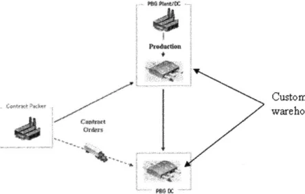
Figure 2 describes the PBG supply chain. PBG operates on a "direct store delivery" system, with
products sold, delivered and merchandised by PBG employees. There are three types of
customers served: contract, ad hoc, and routine. The contract and ad hoc customers place their
own orders and receive product directly from PBG plants. PBG forecasts demand for the routine
customers, and this product is delivered direct to the customer from the plant or via satellite
warehouses. Of the products PBG offers, some are produced in PBG owned bottling plants,
while others are ordered from contract packers. Contract orders are shipped to either plants or
satellite warehouses, and then from there on to customers.
Orfrnid
Figure 2: PBG Supply
Chain5Aiti HCut -W
E3i~~
The supply chain group within PBG is broken into three main groups as shown in the
organization chart in Figure 3: Supply Chain Systems, Warehouse Operations, and Integrated
Planning (IP). The integrated planning group is responsible for demand forecasting and
production planning.
Director
Supply Chain Systems Wa
Vice President Supply Chain Director rehouse Operations
]
Director Integrated PlanningFigure 3: Pepsi Bottling Group Supply Chain Organization Chart
11
-LFM Intern
' Figure adopted from Aret6 Inc.
Eu,,. Em3E3EWINESf f Lr son Ili ;s Figure 4: Pepsi-Cola U.S. Bottling Network -12 -__ -a - - -.
-1.3 Manufacturing Operations Background
Each manufacturing plant is capable of producing a certain array of SKU's (stock keeping units).
Some plants, for example, do not have the capability of producing non-carbonated soft drinks,
such as bottled water. Decisions are made periodically to add product capabilities to some plants
while removing them from others. These decisions are driven largely by capacity constraints and
differences in variable production costs. Some plants run more efficiently than others for various
reasons, allowing them to produce products at lower costs.
Within a plant, switching from production of one type of product to another incurs a certain
amount of setup time. This time is influenced by the two types of changes: flavors and packages.
Large tanks contain the flavored syrup base for the various soft drinks, and switching from one
flavor to another requires the tanks to be cleaned. Package changeovers require adjustments to
be made on the production lines, such as feed rates.
1.4 Products
SKU's in the soft drink business are defined by unique combinations of flavor and package.
Figure
5
below shows the flavors offered by Pepsi, and Figure 6 shows the product mix (as a
percentage of total volume) in the U.S. and Canada.
a
*EU
dot~b1es~ot
I
PEPS
Figure 5: PepsiCo flavor portfolio6
6 Pepsi's website: <http://pepsi.com/pepsi-brands/allbrands/index.php>
- 13
-PrSi
Figure 6: U.S./Canada brand mix7
One major distinguishing factor amongst the flavors offered is carbonated (e.g., Pepsi) vs.
non-carbonated (e.g., Aquafina) soft drinks. Another distinguishing factor is contracted vs.
manufactured products. Some of the products listed in Figure
5
(such as Sobe and Tropicana
Juices) are not produced in PBG plants
-
instead, they are purchased from contract
manufacturers.
The packages are broken down into three main categories: cans, bottles, and fountain drinks.
The cans and bottles are available in different sizes and configurations to address varying needs
and price points. Fountain drinks are those dispensed from machines, as typically found in fast
food restaurants. This type of product is delivered as a syrup in 3 or
5
gallon bags.
1.5 Pepsi Bottling Group Service Model
When the Pepsi Bottling Group was spun off from Pepsi-Cola in 1999, the intention was that it
would focus on the operations and service aspect, while Pepsi-Cola would focus on the
marketing aspect. This is made clear by the slogan adopted by PBG: "We sell soda". The
underlying goal of the company, however, is to achieve outstanding customer service. To that
end, PBG has adopted a three phase service model. The three main phases identified in the
service model are: before the store, in the store, and after the store.
1.5.1 Before the Store
The service model begins before the store. In this phase, a planner uses a software program to generate a demand forecast. The software utilizes future retail pricing and promotion plans among other inputs to determine this forecast. The forecast in turn becomes an input to another software application that is used to create a schedule for producing, ordering, and shipping products to sales and distribution warehouses for subsequent delivery to customers. At the warehouse, inventory levels are closely monitored and safety stock levels maintained to ensure all products are available to meet customer needs.
1.5.2 In the Store
The service model continues inside the stores. PBG essentially follows a vendor managed inventory model - sales representatives visit stores, check inventory levels, place orders for routine customers, and provide in store merchandising service. These representatives travel with wireless handheld computers (similar to the one shown in Figure 7) that contain data about delivery dates, in store inventory, displays/promotions, and retail pricing. This information, when combined with relevant sales history, is used to create customer orders that will satisfy local market demand until the next delivery occurs.
Figure 7: Wireless Handheld Computer8
1.5.3 After the Store
The third phase of the service model occurs after the sale. Each year PBG makes over 600,000 equipment moves and 2 million service calls. When PBG receives a customer service request,
8 Symbol's website: <http://www.symbol.com/PDT8
100/>
-they employ a "solve by sundown" policy. The goal is to respond to all requests by the end of the day the customer call is received. Each year, PBG surveys more than 5,500 customers to ensure they are meeting all expectations.
1.6 Project Motivation
The Pepsi Bottling Group supply chain is quite complex, with an ever growing portfolio of SKU's. Currently, there is no robust method of determining the optimal sourcing strategy - in which plant(s) to produce each product. The goal is to develop an approach that allows PBG to determine where products should be produced to reduce overall supply chain costs while meeting all relevant business constraints.
1.7 Thesis Structure
This thesis is organized into seven chapters, described below:
Chapter 1, Introduction and Overview: This chapter provides background on the Pepsi Bottling Group, and describes the project which led to the research in this thesis. It also outlines the structure of the thesis.
Chapter 2, Supply Chain Optimization Background: This chapter provides a framework for analyzing the capabilities that drive supply chain excellence. It additionally provides some background on sourcing optimization, and more detail on the type of problem that is being
addressed at PBG.
Chapter 3, Developing a Model for Sourcing Optimization: This chapter demonstrates the development of the supply chain model by describing the model inputs and the formulation of the objective function.
Chapter 4, Analysis of Model Output: This chapter describes the results of the baseline assessment and optimization scenarios.
Chapter 5, Implementation of Optimization Tool: This chapter describes the process for implementing the optimization tool into the existing PBG infrastructure.
Chapter 6, Organizational Change Analysis: This chapter examines the thesis work from the three perspectives of organizational processes: strategic design, political, and cultural.
Chapter 7, Conclusion: This chapter summarizes the findings in previous chapters and provides a series of lessons learned.
-17-Chapter 2: Supply Chain Optimization Back2round
This chapter establishes a framework for the capabilities that promote supply chain excellence.
It further provides some background on sourcing optimizations. It goes on to examine in detail
the problem within PBG that is being solved. The chapter concludes by analyzing the specific
area within this framework that is addressed in this thesis, and the motivation behind it.
2.1 Layers of Supply Chain Excellence
The competitive nature of the soft-drink bottling industry requires the need to develop
advantages wherever possible. To get ahead, companies must continually make decisions that
reduce cost and increase profits throughout the supply chain. Figure 8 describes four layers of
capabilities that drive supply chain excellence.
9I Hek~
Figure 8: Capabilities required to achieve supply chain excellence9
These four layers, starting at the core, are:
Strategic network design: This layer features two types of strategies: network configuration and sourcing strategy. Network configuration involves determining the optimal number, location and size of warehouses/plants. Sourcing strategy involves determining which plant/vendor should produce which product. The objective of this layer is to minimize total costs (sourcing,
production, transportation, inventory) by evaluating optimal trade-offs.
The BASF corporation 10, a chemical company, provides an example of a network configuration project. The BASF supply chain network includes a fragmented network of distribution centers. A network optimization model was developed with the objective of determining the optimal number and location of distribution centers. As a result of the optimization, a more efficient network with fewer, more consolidated distribution centers was implemented. Savings of millions of dollars were reported, in addition to dramatic improvements in customer service.
Supply chain master planning: This layer involves coordinating production, distribution strategies, and storage requirements by allotting supply chain resources in a manner emphasizing profit maximization or cost minimization. Master planning gives companies the ability to plan
ahead for seasonal effects, potential promotions, and restrictive capacities.
An example of a supply chain master planning project can be seen in a project undertaken at the 7-Eleven corporation in Taiwan". 7-Eleven operates over 3,000 stores throughout Taiwan, and all of these stores require a daily replenishment. This highly complex network, combined with factors such as crowded roads and increased competition required 7-Eleven to develop a planning solution that would increase efficiency and reduce costs. They implemented software that helped determine a master plan for routing schedules (how much to deliver and when) over an extended time period. Prior to the implementation, the various distribution centers decided their own delivery schedules independently. The master plan helped avoid the otherwise
10 Lee, Young, "Supply Chain Optimization Models in a Chemical Company." BASF Corporation. February 27, 2002.
" Manugistics: [e-journal] <http:// www.manugistics.com/documents/ collateral/0841_0105_7-1 1_casestudy.pdf>
19-common conflicts in delivery schedules between the different distributors, ensuring prompt delivery of goods to each store. The immediate results were a reduction of the miles driven in transporting goods, thus reducing transportation costs.
Operational planning: This layer is much more tactical, with planning horizons typically weekly to daily. The emphasis lies on developing feasible strategies, as opposed to optimized
solutions. Operational planning systems include:
" Demand planning: generate demand forecasts based on historical data and other drivers such as promotions and new product introduction.
* Production scheduling: generate production schedules based on master plans or demand forecasts.
* Inventory management: generate inventory plan for warehouses based on average demand, variability, and lead times.
" Transportation planning: generate transportation routes and schedules.
The Luxottica Group, an eyeglass frame manufacturer, provides an example of an inventory management project . Luxottica distributes its products in 120 countries through 29 wholly-owned branches and 100 independent distributors. Their products have a wide range of seasonality and lifecycles - some are non-seasonal with long lifecycles (everyday frames),
whereas others are highly seasonal (sunglasses). Each warehouse, however, had the same inventory policies for all products regardless of product mix. Luxottica thus implemented
software that helped strategically determine the right inventory policies for each distinct product. As a result of this implementation, inventory levels were reduced by 10% while maintaining the same high service levels.
12 Bodenstab, Jeffrey, "Consumer Products Industry Inventory Management Case Study." [e-journal] <http://logistics.about.com>
Operational execution: These systems provide the data, transaction processing, user access and infrastructure for running a company.
* Enterprise resource planning: systems that integrate all facets of the business, including planning, manufacturing, sales, marketing, human resources, and finance.
" Customer relationship management: systems that track and update customer interactions.
* Supplier relationship management: systems that provide an interface for suppliers for transaction exchanges.
" Supply chain management: systems that provide tracking of activities in plants and warehouses.
" Transportation systems: systems that provide for tracking of goods in transport.
Creative Closets Ltd. designs and installs custom storage systems. Through their early years, Creative Closets primarily used a paper-based system to manage their daily operations. As the company grew and the processes became more complicated, it became increasingly more difficult to use only paper to communicate information. Thus, a web-based ERP system was implemented, resulting in improved workflow and communications. They were able to reduce the staff by 15% while increasing revenue by over 10% in the same period.1 3
The focus of the internship at the Pepsi Bottling Group was on the core of Figure 8, strategic network design. Within this core, the specific focus of the internship was on sourcing strategy. A secondary focus of the internship was on the second layer, supply chain master planning.
13 Exact Software: [e-journal] <www.exactamerica.com/macola/customer.html>
-2.2 Sourcing Optimization Background
The key question addressed in a sourcing optimization is where to make each particular product. Arriving at optimal sourcing solutions involves evaluating a number of tradeoffs while
considering the constraints inherent to the process. One of the tradeoffs involves the number of products produced at a location. From a manufacturing perspective, it would be ideal to
minimize the number of products produced at a plant. This will minimize changeover costs and setup times, and the longer runtimes for each product will help take advantage of scale
economies. From the transportation perspective, it would be beneficial to maximize the number of products at each facility. This will bring products closer to consumers, thus minimizing transportation costs. Additionally, it will allow for quicker response times to issues such as
stockouts. Another issue to consider may be proximity to raw materials. It may be advantageous to produce products near the relevant suppliers in order to reduce lead times. Additionally, there may be opportunities to receive backhaul credits from suppliers by using internal fleet to pickup and deliver raw materials.
2.3 Planning Problem at PBG
In the current process, an optimized sourcing matrix defining which plants provide which warehouses with the demanded products is created once a year for the North American
operations of PBG. This is accomplished using a series of Microsoft Excel based models. The results of the Excel optimization are distributed to each business unit as a recommended sourcing plan, and it is at their discretion whether or not to implement the suggested sourcing decisions. Generally, only some of the recommended decisions are adopted when the plan is distributed. For the most part, sourcing decisions and changes are made independently within the various business units. The following are some of the drivers that dictate these decisions made by the business units:
Strategy: Some plants are more efficient than others, giving them a cost advantage. These efficiencies are monitored and occasionally decisions are made to move entire packages from one plant to another, typically within the same business unit.
Capacity: At various times of the year, some plants are far more utilized than others. If they encounter capacity issues, it may be necessary to source some products at other plants (again, typically within the same business unit).
Convenience: On occasion a certain plant will have excess raw materials for particular packages, and therefore that plant may produce those packages in lieu of other plants.
Downtime: If a line at a certain plant goes down, it is necessary to make adjustments to the sourcing plan to accommodate.
In effect, incremental changes are made to a base sourcing plan throughout the year. This
method has a number of drawbacks. From a technology perspective, the Excel based model is an extremely labor intensive process. It is understood and executed by one individual in the
company, which could cause problems should that individual move on to a different role. Due to the manual nature of the model, it is run only once a year. This requires a forecast horizon of a full year, for which the accuracy is extremely poor. An annual model also does not take into account the large seasonal effects seen in the business. Many of the inputs and constraints in the model could change through the year, and these changes are not accounted for. Lastly, the Excel model provides output in a format that is difficult to interpret.
All of these reasons have led the various business units to make sourcing decisions on their own, based on the drivers described above. This process has led to another set of problems. First, a lack of central control in the sourcing process can lead to inefficiencies. Multiple people have authority to make sourcing changes that may not necessarily be optimal. Second, allowing individual business units to make decisions independent of other units promotes local optimizations. Decisions are made that don't consider the supply chain network as a whole.
For these reasons, the Pepsi Bottling Group is in search of a more robust method for determining the sourcing strategy. A more integrated solution could provide numerous benefits over the existing Excel based methodology, including the opportunity for more frequent updates to the sourcing plan. This could help address the issue of seasonality effects, in addition to ensuring
-that more current and thus more accurate data is reflected in the model. There is the additional
question regarding the efficacy of the Excel based optimization engine. The PBG network
contains an enormous amount of complexity, and it is possible that a more powerful optimization
approach could reveal further cost benefits.
Chapter 3: Developing a Model for Sourcing Optimization
This chapter demonstrates the development of the supply chain model. It describes the model
inputs and the formulation of the objective function.
3.1 Model Overview
The goal is to model part of the supply chain network described in Figure 2, specifically the
portion shown in Figure 9. Featured in this model are PBG Plants, plant attached warehouses,
satellite warehouses and contract packers. End customer demand is aggregated to the warehouse
level, so the warehouses are in effect treated as customers. Contract products are shipped
directly to customers (warehouses), impacting only transportation costs.
Customer demand aggregated to
a
~warehouse
levelFigure 9: Portion of supply chain network modeled 4
3.2 Model Inputs15
The following is a list of required data inputs:
" Products
* Plants
14 Figure adopted from Aret6 Inc.
15 "LogicChain®: User Reference Guide." LogicTools. 2005.
-. Production " Transportation " Customers
The following sections will take a closer look at these key model inputs. 3.2.1 Products
The following list describes the product details required as inputs:
Weight: Weight of one unit of product, used for trucking capacity. The unit of measure is defined by the user - for this model pounds were used.
3.2.2 Plants
The key required data inputs for the plants are the physical locations. Through a method known as "geocoding", the necessary longitude and latitude values are determined to geographically model the location of the plants.
3.2.3 Production
The following list describes the production details required as inputs:
" RT Available Hours: Total number of "regular time" (i.e., non-overtime) production hours that are available for the selected production line during each time period.
" RT Production Cost: Per unit production cost associated with Regular Time production hours for each time period.
" Min Lot Size: If a particular item is produced, the minimum number of units that the selected production line must make during each time period.
" Lot Increment: Incremental number of units that must be produced by each production line when the Min Lot Size is exceeded during a time period. The actual number of units produced will be a multiple of the Lot Increment.
* Capacity Required: Number of hours required to create one unit of the selected product on the selected production line during the selected time period.
3.2.3.1 Plant Variable Cost
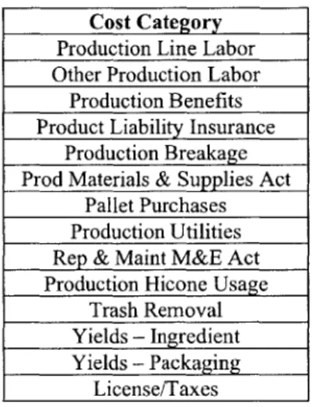
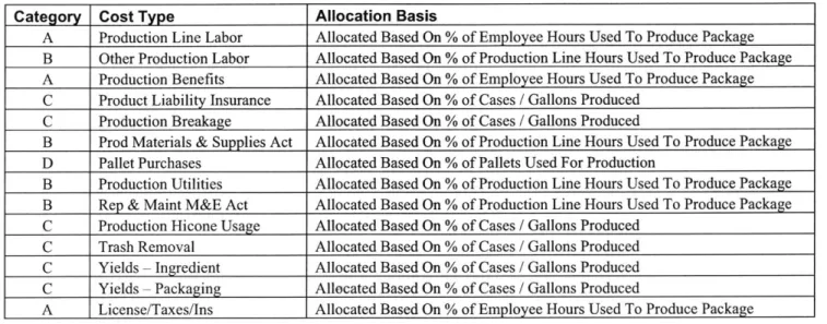
Production costs per unit were created for each package at each plant. PBG records aggregate production cost data at the plant level - it was therefore required to disaggregate these costs down to the package level. Historical manufacturing cost figures were obtained for 14 cost categories at the plant level. Table 1 summarizes the cost categories used to develop the plant variable costs:
Table 1: Production variable cost categories
Cost Category Production Line Labor Other Production Labor
Production Benefits Product Liability Insurance
Production Breakage Prod Materials & Supplies Act
Pallet Purchases Production Utilities Rep & Maint M&E Act Production Hicone Usage
Trash Removal Yields - Ingredient Yields - Packaging
License/Taxes
Costs were allocated to the in Table 2:
package level from the plant level using four categories, summarized
Table 2: Variable cost allocation categories
Category Description
A Employee Hours Used to Produce Package B Production Line Hours Used to Produce Package
C Cases / Gallons Produced
D Pallets used for Production
-27-Table 3 summarizes how each of the 14 cost categories were allocated to the package level using
the four allocation categories.
Table 3: Variable cost allocation basis
Category Cost Type Allocation Basis
A Production Line Labor Allocated Based On % of Employee Hours Used To Produce Package B Other Production Labor Allocated Based On % of Production Line Hours Used To Produce Package A Production Benefits Allocated Based On % of Employee Hours Used To Produce Package C Product Liability Insurance Allocated Based On % of Cases / Gallons Produced
C Production Breakage Allocated Based On % of Cases / Gallons Produced
B Prod Materials & Supplies Act Allocated Based On % of Production Line Hours Used To Produce Package D Pallet Purchases Allocated Based On % of Pallets Used For Production
B Production Utilities Allocated Based On % of Production Line Hours Used To Produce Package B Rep & Maint M&E Act Allocated Based On % of Production Line Hours Used To Produce Package C Production Hicone Usage Allocated Based On % of Cases / Gallons Produced
C Trash Removal Allocated Based On % of Cases / Gallons Produced C Yields - Ingredient Allocated Based On % of Cases / Gallons Produced C Yields -Packaging Allocated Based On % of Cases / Gallons Produced
A License/Taxes/Ins Allocated Based On % of Employee Hours Used To Produce Package Figure 10 and Figure 11 show an example graphically of how the plant variable costs were calculated. Hypothetical "Plant A" produces three packages (6, 12 and 24 pack of cans). Percentages for each cost allocation category were calculated for each package - the example highlighted is the 24 Pack Cube package. The total amount of employee hours spent at Plant A were 726, out of which 255 were spent on the 24 Pack. Therefore, the percentage of employee hours allocated to the 24 Pack is 255/726, or 35%. The same process is used to obtain the percentage breakdowns for the other three cost allocation categories across all packages.
Can Production Line % Breakdowns
Package Line Line Emp Cases Pallets % Line % Emp % Cases % Pallets Hrs Staffing Wie.., Prod. Prod. Hrs Hrs Prod Prod
Plant A 242 1.4 26j 110,000 1100 B A C D
6 Pack Cans 112 3 336 50,000 500 46% 46% 45% 45%
12 Pack Cans 45 3 135 25,000 250 19% 19% 23% 23%
24 Pack Cube 85 3 55 35,000 350 35% 350 32% 32%
r
% Employee Hours (A) for 24 pk = 255/726 = 35%Figure 11 shows the next step, which is using the cost allocation percentage breakdowns to
obtain the variable costs. The cost categories are listed in columns (not all categories are
depicted in this example) for the same hypothetical "Plant A". The example highlighted is the
24 Pack Cube package. In this theoretical time period, 35,000 cases of this package were
produced. The first cost item in the figure (third column) is production line labor, and Table 3
above indicates that this cost category is allocated based on percentage of employee hours used.
The example in Figure 10 showed that 35% of the total employee hours at Plant A were allocated
towards producing the 24 Pack package. From Figure 11 we know that in Plant A a total of
$10,000 was spent on production line labor. Thus, 35% x $10,000
=
$3500 allocated to the 24
Pack for production line labor. The same technique is used for all cost categories. These
package level costs are then summed and divided by the total cases produced for the particular
package of interested to obtain the variable cost per case.
A B A C C B
Cases Production Othe Production Product Production
Package Produced Line Labor Production Benefits Liability Breakage Materials & Total CPU Labor
Insurance
Suplies
ActPlant A 110,000 $ 10,000 $ 15,000 $ 10,000 $ 8,000 $ 5,000 $ 10,000 $ 0.53 6 Pack Cans 50,000 $ 4,600 $ 6,900 $ 4,600 $ 3,600 $ 2,250 $ 4,600 $ 0.53 12 Pack Cans 25,000 $ , $ 2,850 $ 1,900 $ 1,840 $ 1,150 $ 1,900 $ 0.46
24 Pack Cube 35,000 $ 3,50 $ 5,250 $ 3,500 $ 2,560 $ 1,600 $ 3,500 $ 0.57 Line Labor for 24 pk =
$10,000 x 35% = $3,500
Figure 11: Calculation of variable cost per unit
3.2.4 Transportation 3.2.4.1 Carrier Types
Two main types of carriers were considered:
" Internal fleet: This fleet consists of trucks owned internally by the Pepsi
Bottling Group. When sent out, these trucks must make a return trip to
the originating location.
" Common Carrier: This is a fleet of trucks subcontracted to outside agencies. These
trucks make one way trips.
-There are certain rules in place that dictate which type of carrier is used to ship product to warehouses. At some plants, no internal fleet is available, and all product shipped out is done so
via common carriers. At other plants, both carrier types are available, and either can be used. In these cases, the distance the truck needs to be shipped dictates the decision. Typically, a truck from the internal fleet will only be sent if it can fulfill its shipment and return in the same day. This translates to one-way distances of approximately 250 miles, or 500 miles roundtrip. Distances longer than this generally utilize common carriers.
3.2.4.2 Mileage Estimation
A key input required is an estimation of mileage between two locations. Defining the following variables:
p circuity factor to correct for actual road distance
lona longitude value of location "a"
lata latitude value of location "a"
lonb longitude value of location "b"
latb latitude value of location "b"
R radius of the earth in miles
Dab distance from point "a" to point "b"
The distance between two points "a" and "b" can be defined as16:
Dab = p x (2xfx ) x 2 x arcsin( (sin(ata latb)) 2 + cos(lat) X cos(lat) x (sin( " onb v
2
360 2 2
The longitude and latitude values are obtained as described in section 3.2.2.
The formula is essentially calculating straight-line distances (accounting for the earth's curvature) between points "a" and "b", with the circuity factor correcting for actual road
distance. This value is typically 1.1417 for the continental United States. The term (
)
360 represents the number of miles per degree of latitude, and is used to convert the angular distance into miles. Databases within the PBG system had actual distances traveled by trucks for the existing lanes - for these, actual distances were used as opposed to calculated. For potentially new lanes, however, this formulation was utilized.
3.2.4.3 Transportation Cost Formula
Transportation costs in the model are calculated by developing a per unit per product cost for each lane. Defining the following variables:
cpm cost per mile
Dab distance from point "a" to "b"
w weight per unit of product u utilization of truck
tc capacity of truck
The cost of shipping a unit of product can be defined as:
cpm x Dab X W
U X tc
The per mile cost was calculated using internal financial cost reports: dividing total
transportation expenses for a given period by the total miles driven in that period. The truck utilization refers to the percentage of a truck's capacity that is filled with product - for this
model, 95% utilization was assumed. The truck capacities were calculated by taking the average payloads from a given period of time.
-31 -7 Ibid., p. 32
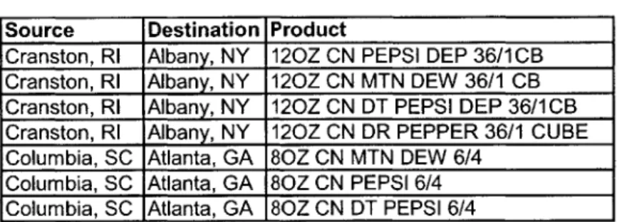
3.2.4.4 Pre-Defined Sourcing Matrix
For the baseline models, the existing sourcing matrix is a required input. This matrix dictates the flow of product through the network by assigning each customer (warehouse)/SKU combination with a specific plant. Table 4 below shows an example of this matrix.
Table 4: Baseline sourcing matrix Source Destination Product
Cranston, RI Albany, NY 120Z CN PEPSI DEP 36/1CB Cranston, RI Albany, NY 120Z CN MTN DEW 36/1 CB Cranston, RI Albany, NY 120Z CN DT PEPSI DEP 36/1CB Cranston, RI Albany, NY 120Z CN DR PEPPER 36/1 CUBE Columbia, SC Atlanta, GA 80Z CN MTN DEW 6/4
Columbia, SC Atlanta, GA 80Z CN PEPSI 6/4 Columbia, SC Atlanta, GA 80Z CN DT PEPSI 6/4
For example, this table tells us that in the existing process, the Albany, NY warehouse receives its 12 oz Can 36 Pack package from the Cranston, RI plant.
3.2.5 Customers
For this project, the satellite warehouses were treated as the end customers. The main inputs to be considered were:
* Location " Demand
The locations of the customers were specified via latitude and longitude coordinates, as
described earlier. The demand input was given special consideration for the baseline scenario. Historical demand forecast data was available, but when taking into account the forecast error, this was not the best representation of "true" demand. Another input available was shipment data, and this was the best representation of the true historical demand. For satellite warehouses, the demand was simply the shipments received (satellite warehouses don't act as hubs, and therefore product is not shipped out). Plant-attached warehouses were slightly more complicated. Of the production from the attached plant, some product remained at the warehouse, while the remainder was shipped out to other warehouses. Additionally, these warehouses could receive product from other plants. Therefore, demand at the plant-attached warehouse was defined by the following flow balance:
Demand = manufactured product + shipments in - shipments out
Figure 12 below graphically demonstrates this.
manufactured product
shipment shipments in out
Satellite warehouse Plant-attached warehouse
Figure 12: Customer demand in the baseline scenario 3.3 Formulation of Model
The objective of the optimization is to minimize total landed cost. Defining the following variables:
xk;; amount in cases/gallons of product k produced in plant i and shipped to customer]j
mki cost in dollars of producing 1 case/gallon of product k in plant i
tki, cost in dollars of transporting 1 case/gallon of product k from plant i to
customer]
mb minimum lot size
LI lot increment
P; capacity of plant i
Dj total demand of customerj
a number of plants
b number of customers
c number of products
-The objective function is:
a b c a b c
Min(Cost) = ZZ m xkY + IEtkiXkU
i=1 j=1 k=1 i=1 j=1 k=1
The goal is to minimize total cost, with the two main cost drivers being transportation and manufacturing (plant variable costs).
The objective function is subject to the following constraints:
b c
I xAL < Pk 1,.. .,a (capacity constraint)
j=1 k=1 a C x1 >0
D
j
1, ..
.,b(fuilfill demand)
i=1 k=1 X > 0b xki>mb
kyj# fraction
LIi,j,k
= 1,...,a,b,c
i,j,k = 1,...,a,b,ci,j,k
= 1,.. .,a,b,c(produce positive amounts)
(minimum batch size)
(produce multiples of lot increment)
This is a single period model, and the intent is to run the model over multiple periods to account for seasonality. Additionally, it should be noted that this model does not account for inventory. Optimization of various levels and locations of inventory is addressed by other PBG systems. 3.4 Modeling Tool Background
The analysis tool enlisted for this optimization was LogicChain@, developed by Logic Tools, Inc. The software provides two distinct types of solutions:
Multi-site Production Sourcing Solution: This aspect of the tool helps determine the optimal sourcing strategy when a firm has choices deciding where each SKU should be produced or purchased from.
Master Planning Solution: This aspect of the tool helps determine the optimal quantity and timing of production, storage and flow decisions.
As mentioned earlier, the primary focus of this study has been on the first solution the tool
offers. The master planning solution aspect was evaluated in a secondary focus, and those
results will be discussed in Chapter 4.
3.5 Methodology
Four key steps were identified to perform the sourcing optimization:
Step 1: Build a model representing PBG supply chain
Step 2: Evaluate a baseline: simulate actual product flow through the network
for a given period of time, and compare theoretical costs to actual costs.
Step 3: Optimize the baseline: determine potential opportunity for the given
time period
Step 4:
Input forecast data for future periods to develop recommended sourcing
strategies
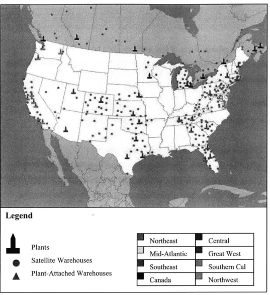
Figure 13 below shows a graphical depiction of the Pepsi Bottling Group supply chain as
modeled in the LogicChain@ software. The color scheme indicates the different business unit
classifications. The legend below the map describes the contents of the figure in full.
-Legend
I
PlantsSatellite Warehouses
A Plant-Attached Warehouses
Northeast Central Mid-Atlantic Great West Southeast Southern Cal
Canada Northwest
Figure 13: Pepsi Bottling Group supply chain network
The network as a whole is quite complex, containing millions of decision variables. To manage this complexity, the modeling and analysis for this project was broken down into two main stages, summarized in Figure 14. Stage 1 involved modeling the Central Business Unit, which contained 3 plants and 22 satellite warehouses. Stage 2 involved addressing the more
complicated East Coast, which featured three separate business units containing a total of 20 plants and 149 total warehouses.
Total
Plants: 20 Warehouses: 149
SKU's: 780
Figure 14: Stage I vs. Stage 2
- 37
-.C
Stage 1: Central Business Unit Plants: 3
Warehouses: 22
SKU's: 400
Stage 2: East Cost
Business Units: 3 Northeast Business Unit Plants: 4
Warehouses: 38
Mid-Atlantic Business Unit Plants: 9
Warehouses: 51
Southeast Business Unit Plants: 7
Chapter 4: Analysis of Model Output
This chapter describes the results of the analysis of the supply chain model. It shows the
baseline assessment and goes on to discuss the results of the optimization scenarios. The first
part of the chapter looks at the results from stage one (central business unit), and the second part
of the chapter moves on to the results from stage two (east coast business units). The chapter
concludes with an analysis of a supply chain master planning scenario.
4.1 Central Business Unit Model Analysis
The purpose of the baseline model is to simulate actual product flow through the supply chain
network for a given period of time, and compare theoretical output obtained to actual output.
The goal is to establish confidence that the model accurately represents the business.
The following output from the model will be compared with actual data:
* Production Volume
* Production Cost
* Transportation Cost
The actual data is obtained from PBG internal reporting systems.
4.1.1 Central Business Unit Baseline Model
Table
5
below shows the baseline results from the Stage 1 model at the plant level. This model
was based on one period (4 weeks) of data. Comparisons of production volume, and production/
transportation costs are all within 3%. It can be noticed that the model consistently shows higher
production numbers in comparison to the actual production numbers. This is likely due to the
fact that in reality, some of the product demanded was shipped from existing inventory. The
starting inventory numbers were not readily available and thus not included in the model, so all
of the product demanded had to be produced. The model production costs are all
Table 5: Central Business Unit baseline results Manufacturing Cost
Plant
h
Actual - [ Logic Chain % diff I Actual Logic Chain I % diff CON FIDENTI..A L 0.25% 3.06% 1.04% 1.63% CONFIDENTIAL Transportation Cost4.1.2 Central Business Unit Optimized Model Analysis
After gaining confidence from the baseline model, the next step was to run an optimization scenario. This was done by removing the baseline sourcing strategy and allowing the tool to determine the most optimal sourcing. Table 6 below shows the financial impact of this optimization. It specifically highlights an opportunity to save 9% on the transportation cost. There was a very small savings shown on the manufacturing side, and the overall savings found came to 2.6%
Table 6: Central Business Unit optimization results
Category |Baseline 0ptimized Difference % savings
CONFIDENTIAL
0.6%
9.0%2.6%
Table 7 shows where the tool shifted product to. A clear shift of production from Detroit to Howell can be seen, with Detroit production down 14% and Howell production up 8%.
-39 -Units Produced Burnsville Howell Detroit Total
Total Production Cost
Total Transportation Cost
0.50% 2.77% 2.08% 1.81%
Plant Actual Logic Chain % Diff
Burnsville $ Howell $ CONFIDENTIAL Detroit $ 2.69% Total $ 110.27% Trans Cost Total Cost $
Table 7: Central Business Unit optimized scenario production breakdown
Units Produced
Plant
Baseline
Optimized
% change
Burnsville
1%
Howell
CONFIDENTIAL
8%
Detroit
-14%
Figure 15 shows an example of some of the decisions the tool is making that is resulting in this production shift8. Specifically, much of the production of the 12 oz Can 12 Pack and 2 liter bottle was shifted from the Detroit plant to the Howell plant. In fact, the software recommended moving all of the 2 liter bottle production in Detroit to Howell.
Detroit,
MI
PlantLine Packaqe Baseline Prod Optimized Prod.
0
%diff Can Line 12LZ CN 12/2 FM (12PACK) 628,430.00 525,200.00 -16%Catn 2 LITER PL 1/8 SHELL (LOOSE) 67,908.00 - -100% _
116.90 LPK12r
Howell, MI Plant
Line Package Baseline Prod Optimized Prod. % diff Can Line 120Z CN 12/2 FM (12PACK) 730,425.00 839,034.00 15%
12 LITER PL 1/8 SHELL (LOOSE) 763,576.00 826,668.00 8% Bottle Line
CO)
7
J24UZ PL P-K b14 6HEILL (6PA(UK)j 11 b,4Ub.UU I II, t2b.UU 1 -1701 Figure 15: Production comparison between Detroit and Howell in optimized scenario Table 8 helps to explain why this shift may have occurred. The first two rows of this table show a comparison of the variable production costs of these two packages in Detroit, relative to Howell. The 12 oz Can 12 Pack package costs $.20 more per case to produce in Detroit, and the 2 liter bottles cost $.17 more per case. Thus, it is more costly to produce both of these packages in Detroit versus Howell. The last row of Table 8 shows the average distance of each of these plants from the customers (satellite warehouses). The Howell plant is on average 105 miles from its customers, whereas the Detroit plant is on average 140 miles from its customers. This fact is highlighted by Figure 16, which points out the Howell and Detroit plants on the central business unit map. The Howell facility is clearly more centrally located in the state of Michigan.
I* IN 1
Table 8: Cost comparison of Howell and Detroit plants
Category Howell Detroit cost per unit (120Z CN 12/2 FM (12PACK)) - $ 0.20
cost per unit (2 LITER PL 1/8 SHELL (LOOSE)) - $ 0.17
average distance from customer (miles) 105 140
,H(WeIIA~
Detroit
Figure 16: Location of Howell vs. Detroit 4.1.3 Stage 1 Validation Analysis
A study was done to analyze whether or not the types of savings shown in the Stage 1 optimization scenario would be sustainable from period to period. This was done by first developing an optimized sourcing plan for a future period by using forecast demand data as the input. This period featured lower demand and less complexity than the period simulated in the sourcing study. The existing sourcing strategy was used in actual production, and at the end of the period a "post-mortem" analysis was conducted. The period was simulated, using the optimal sourcing plan instead. The actual production and transportation costs were compared with the model's predicted costs using the optimized sourcing strategy. Table 9 shows the results of this analysis.
-41-Table 9: Results of Stage 1 validation analysis
Category Model-Actual Sourcing Model-LC Optimal Sourcing Savings % Savings
Trans 4%
MFG CONFIDENTIAL 2%
Total 2%
These results indicate that using the optimized sourcing strategy would have offered an opportunity to save 4% on the transportation costs and 2% on the manufacturing costs. This confirmed that the cost savings opportunities were sustainable from period to period, even when demand was not at its peak.
4.2 East Coast Business Units Model Analysis
4.2.1 East Coast Business Units Baseline Model
Similar to Stage 1, a baseline model was developed for the three business units in the East Coast. Modeling these three business units together introduced significantly more complexity. It was necessary, however, in order to accurately simulate the baseline model since a certain amount of sourcing across business unit lines occurred. The existing sourcing plan was locked, and once again any sourcing outside of these three business units was ignored. A historical one-month period was simulated in the model, and actual results were compared to the model results. Figure 17 below shows the results of the manufacturing comparison. Each plant was compared side by side, and then the totals at the BU level were compiled. At the plant level, production and costs numbers in the model were within 3% of actual numbers. At the BU level, these numbers were within 1%.
BU IPlant lUnits Produced ILC Units Prod % duff Actual Cost ILC Cost diff Mid-Atlantic Baltimore New River Newport News Philadelphia Piscataway Roanoke Willamsport Wilminaton Albany, NY Auburn, ME Northeast Cranston, RI Johnstown, PA Laurel Packa in2 Atlanta, GA Columbia, SC Jacksonville, FL Knoxville, TN Nashville, TN Orlando, FL --- El 4. 1 -2.2% -2.0% 0.5% 1.7% 2.2% 4.1% 3.9% A 0O/ $ $ $ $ $ t CONFIDENTIAL CONFIDENTIAL CONFIDENTIAL CONFIDENTIAL
Figure 17: East Coast baseline model evaluation
A similar comparison was done for the transportation side. Figure 18 shows the results of this comparison. Again, the results are broken down by originating plant and then summarized at the business unit level. At the business unit level, the model costs are within 1% of actual costs.
-43 --1.7% 1.6% -1.5% 1.4% 2.2% 1.6% 3.2% Southeast 1.4%1 $1 2.5% $2. -2.7% $ CONFIDENTIAL -2. -0.7% $ -2. 0.8% $ 0. 1.8% $ 2. 1.1% $ 2. -4.4% $ -3. -1.4% $1 0. 0.1% $-0. 3.2% $ 2. 0.8% $ CONFIDENTIAL -1.
BU IPlant jActual Trans Cost LC Trans Cost % diff Mid-Atlantic Baltimore
S$
Cheverly $ New River $ Newport News $ Philadelphia $ Piscataway $ Roanoke $ Willamsport $ Wilmington Albany, NY $ Auburn, ME $ Northeast Cranston, RI $ Johnstown, PA $ Laurel Packagin$
Southeast Atlanta, GA Columbia, SC $ Jacksonville, FL $ Knoxville, TN $ Nashville, TN $ Orlando, FL $ CONFIDENTIAL CONFIDENTIAL CONFIDENTIALFigure 18: East Coast model transportation cost comparison
The baseline model comparisons provided confidence that our model accurately predicted reality. The next step was to move on to the optimization scenarios.
4.2.2 East Coast Model Optimization Scenarios
Figure 19 shows the results of the optimization scenario run for the East Coast model.
The optimization demonstrated an opportunity to save 7% on the manufacturing side and 3% on the transportation side.
Category Baseline Optimized Savings % save
MFG $ CONFIDENTIAL . .
Trans $ 3%
Total $ 6%
Figure 19: East Coast model optimization scenario
2.7% -1.4% -3.3% 2.3% 3.1% 3.0% 3.5% 3.4% -2.5% 5.4% -3.0% -2.9%0 2.6% 1.6% -1.4% 2.2% 4.2% 1.5%, A n10/_ $ $
In the optimization scenario, there was a significant increase in cross business unit sourcing. In
practice, this does not happen as frequently since each business unit is essentially running as its
own profit-loss center. There is a separate director for each BU, and they run their respective
units quite independently. The software clearly found it advantageous, however, to source
outside these boundaries. Figure 20 demonstrates the increase in cross business unit sourcing. In
the baseline scenario, 19% of the product being shipped out of the Northeast BU was headed to a
different BU. The Mid-Atlantic and Southeast BU's each shipped 1% of their products outside
their respective boundaries. In the optimized scenario, the Northeast BU saw a 7% increase in
product shipped outside their boundaries, and the Mid-Atlantic and Southeast business units saw
increases to 4% and
5%
respectively.
Shipped Out
BU Actual LC Optimized
Northeast 19% 26%
Mid-Atlantic 1% 4%
Southeast 1% 5%
Figure 20: East Coast cross Business Unit sourcing
A look back at the East Coast map shown below in Figure 21 can help explain much of the
increased cross business unit sourcing. As a reminder, the magenta plants are a part of the
Northeast business unit, whereas the yellow plants are a part of the Mid-Atlantic business unit.
Highlighted in Figure 21 is a plant in the Northeast business unit that is geographically situated
within the boundaries of the Mid-Atlantic business unit. In practice, many sourcing decisions
were made to keep product flow within business units, and this clearly opens up opportunities for
plants on the border of a business unit line.
-45-Figure 21: The case for cross Business Unit sourcing
4.3 Supply Chain Master Planning