Antibody-Functionalized Nanoporous
Surfaces Enable High Throughput
Specific Cell Capture
bySukant Mittal
B.S. Biomedical Engineering, University of California, Irvine (2005)
S.M. Electrical Engineering and Computer Sciences, Massachusetts Institute of Technology (2008)
Submitted to the Harvard-MIT Division of Health Sciences and Technology in partial fulfillment of the requirements for the degree of
Doctor of Philosophy in Medical and Electrical Engineering at the
MASSACHUSETTS INSTITUTE OF TECHNOLOGY June 2012
CMassachusetts Institute echnology 2012. All rights reserved.
ARCHNES
'MASSACHUSETTS INST I OF TECHNOLOGYJUN
LR4 2012
L BRARIES
Signature of Author:Harvard-MIT Division of Health Sciences and Technology May 1 7th 2012 Certified by:
Prof. Mehmet Toner Harvard-MIT Division of Health Sciences and Technology, Massachusetts General Hospital Thesis Supervisor Accepted by:
Prof. Ram Sasisekharan Harvard-MIT Division of Health Sciences and Technology Chairman, Committee for Graduate Students
Contents
A bstract ... 12
A cknow ledgem ents ... 15
Chapter 1...17
Introduction ... 17
1.1 M otivation ... 18
1.2 Thesis Structure ... 20
Chapter 2...24
Background and Prior W ork... 24
2.1 M acroscale separation based on physical properties... 24
2.2 Microscale bioparticle separation techniques based on physical characteristics ... 26
2. 3 Separation of bioparticles based on specific biomolecular recognition ... 30
2.4 Immunochromatography separation using microfluidic devices ... 32
2.5 Historical use of Porous Surfaces in M icrofluidic Devices... 35
2.6 Some Limitations of current microfluidic devices in cell sorting ... 38
2.6 Sum m ary...40
Chapter 3...41
Integration and characterization of nanoporous membranes in microfluidic devices ... 41
3.1 Integration of porous m em branes in m icrofluidic devices ... 41
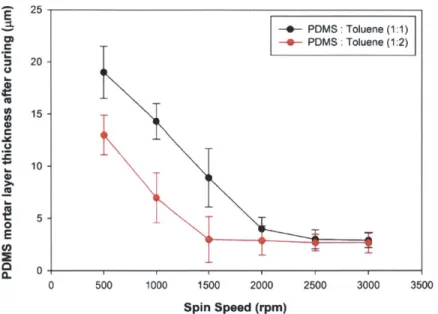
3.1.1 Uncured PDMS binding mortar thickness optimization...43
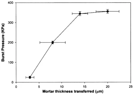
3.1.2 Device strength characterization... 44
3.2 In-situ functionalization of nanoporous membranes incorporated in microfluidic devices for specific biorecognition... 45
3.3 Lum ped resistor m odel... 47
3.5 Fluid flux m easurem ents ... 52
Chapter 4...54
Antibody-Functionalized Fluid-Permeable Nano-Porous Surfaces for Rolling Cell Capture at High Flow Rates ... 54
Intro du ctio n ... 54
4 .1 M eth o d s ... 5 5 4.1.1 Cell sample preparation ... 55
4.1.2 Device Operation ... 55
4.1.3 Imaging and quantitation of specific cell capture ... 57
4.2 Cell Transport to Surface is Enhanced by Diverting Streamlines... 57
4.2.1 Fluid streamlines in a porous surface device ... 58
4.2.2 Cell trajectories in a dilute suspension... 60
4.3 Cell convected to the porous surface portray a rolling motion ... 63
4.4 Nano-porous fluid permeable surfaces decrease surface rolling velocity ... 64
4.5 Comparison of measured cell surface velocity on the porous surface with hydrodynamic Model... 65
4.6 Cell-surface interactions are promoted by a fluid permeable surface ... 66
4.7 Model describing arrest of specific cells based on relative velocity ... 68
4.8 Effect of shear on cell removal... 71
4.9 Cell Capture on Fluid-Permeable Surfaces Exceeds Solid Surfaces at Increased Flow R ate s ... 7 3 4 .10 S um m ary ... 76
Chapter 5...78
Partly-Porous Surfaces Enable Enhanced Cell Capture at High Flow Rates while Suppressing Surface Fouling...78
Introdu ctio n ... 7 8 5.1 Qualitative observations on stagnant layer formation and effect on capture efficiency of targ et cells...79
5.2 Effect of stagnant layers on specific cell capture ... 80
5.3 Theoretical background on stagnant layer formation...82
5.4 Tem poral form ation characteristics of stagnant bioparticle layers... 89
5.4.1 Im age analysis of stagnant layers... 89
5.4.2 Temporal growth of stagnant layers... 89
5.5 Edge effects in m icrofluidic channels ... 93
5.6 Spatially m odulated m icro-flows for enhanced cell capture ... 96
5.6.1 Shear variation on a porous and spatially modulated porous surface ... 96
5.6.2 Effect of partly porous surface on stagnant layer formation... 97
5.6.3 Specific cell capture efficiency on a spatially modulated porous device ... 98
5.7 High throughput cell capture ... 99
5.8 Sum m ary...101
Chapter 6...103
Conclusions and Future W ork ... 103
6.1 Conclusions ... 103
6.2 Outlook ... 105
List of Figures
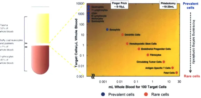
Fig. 1-1 Blood composition and frequency of rare cells for disease diagnosis...19
Fig. 2-1 (a) Modem day ultracentrifuge (b) Bands of different components of blood after ultracentrifugation...26
Fig. 2-2: (a) Comparison of removal characteristics of different pressure driven membrane processes [1] (b) Large scale industrial modules containing porous surfaces for removal of bacteria from water [1] (c) Modem day hemo-dialysis machine for removal of toxins from blood using 15 nm porous surface [2]... 27
Fig. 2-3: (a) Schematic of the interdigitated electrodes and DEP forces with respect the sample flow (b) fractionation of tumor cells and other blood components on the DEP chip [3]... 28
Fig. 2-4: (a) Schematic illustrating the principle of acoustic separation by standing surface acoustic waves (SSAW) generated using interdigital transducers (IDT). The varying acoustic forces repositions the larger cells closer to the channel center and smaller cells farther from the center (b) Cells of varying sizes align at distinct positions across the microchannel cross-section based on the acoustic primary radiation force experienced...29 Fig. 2-5: (a) Top schematic shows asymmetric obstacles separating out particles of different size. The bottom figure shows separation of 0.4 pLm and 1 ptm beads and the respective
trajectories. (b) Top schematic shows the focusing of particle in an annulus. The middle figure illustrated the different forces that determine the eullibrium position of focusing and the bottom figure shows focusing of fluorescent fluid in the microfluidic channels...30 Fig. 2-6 (a) FACS schematic illustrating the principle of FACS (b) Variation of the original FACS principal where droplets are generated encapsulating cells are generated to preserve cells from excessive shear at high flow rates [4]...32
Fig. 2-7 (a) Active method of magnetically activated cell separation using on chip fabricated coils [5] (b) Schematic of passive MACS using an external magnetic to deflect magnetically attached cells [6]...33
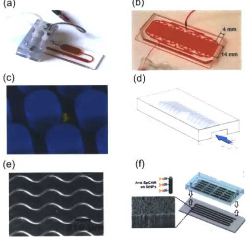
Fig. 2-8 (a) Schematic of a single straight rectangular microfuidic channel and fluid streamlines. (b) Multiple straight rectangular channels with blood in order to improve throughput (c) SEM of
a cancer cell immobilized on an EpCAM coated micro-Silicon pillar (d) Schematic of "herring bone" indentations modifying fluid and particles streamlines to increase interaction with the antibody coated surface (e) Narrow curved channels fabricated using fluidic forces to capture cells (f) Hi aspect ratio CNT forests ("tiny" pillars) developed in conjunction with the herring bone top to enhance specific cell capture...35
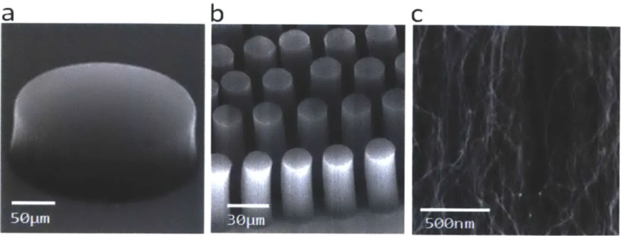
Fig. 2-9 Scanning electron micrographs (SEMs) of patterned VACNT elements (a) A 200gm diameter single post (b) An array of 20gm diameter posts (c) Nanostructure of a VACNT forest
[7] ... ... 37 Fig. 2-10 Scanning electron micrograph of a porous monolith formed inside a microfluidic channel using UV initiation...37
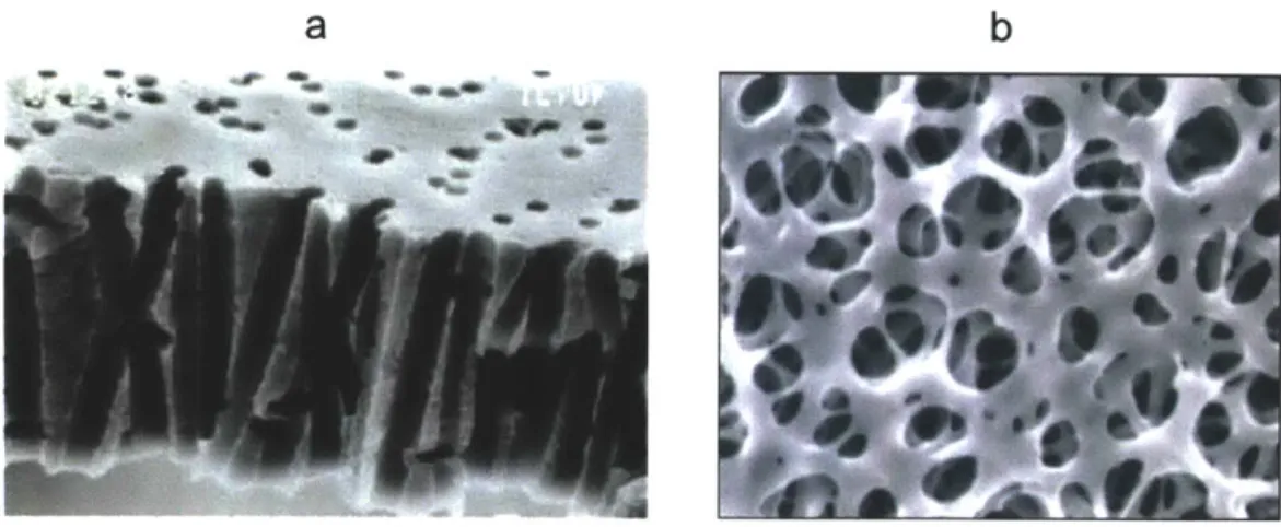
Fig. 2-11 (a) Scanning electron microscopy of a track etched polycarbonate membrane (b) SEM of a cellulose mesh type porous surface... ... 39
Fig. 3-1 (a) Negative photoresist (SU-8, MicroChem) was photolithographically patterned on silicon wafers to create masters. The masters were then used as molds, on which polydimethylsiloxane (PDMS) prepolymer mixed with its crosslinker at 10: 1 weight ratio was poured, degassed, and allowed to cure in a conventional oven at 65 'C for 24 h before removal from the molds. Next, a thin layer of uncured PDMS diluted in toluene (50% v/v) was spun 1800 rpm for 1 min onto a glass slide using a high-speed spinner. (b) The thin layer of PDMS was transferred onto the channel surfaces by gently stamping the PDMS channel onto the uncured PDMS. (c) The polycarbonate membrane was gently placed over the bottom channel first and then the top channel was carefully aligned over it. (d) Gentle compression applied using a clamp (e) The device constructs was allowed to sit at room temperature overnight to cure at 70'C. (f) Exploded view of the porous surface device with dimensions...44
Fig. 3-2 PDMS mortar thickness transferred to the PDMS slabs as a function of spin speed.. .45
Fig. 3-3 Pressure at which the porous surface sandwiched device leaks as a function of the mortar thickness transferred...46
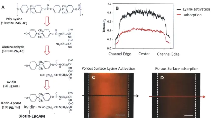
Fig. 3-4 (A) Poly-(L-lysine) functionalization protocol (B) Intensity measurement across the channel for Lysine activated avidin functionalization and adsorption based functionalization (C)
representative image for the lysine activated channel (D) representative image for the adsorption channel... 48
Fig. 3-5 Schematic showing the independent and dependent variables in the integrated nanoporous surface device...49
Fig. 3-6 Lumped resistance model (a) Element resistances (b) Lumped resistor model...50
Fig. 3-7 (a) Experimental and theoretical flow rates through the top and bottom outlets of the device and the ratio of the top flow rate to bottom flow rate as a function of pressure with no external resistances (b) Experimental and theoretical flow rates through the top and bottom outlets of the device and the ratio of the top flow rate to bottom flow rate as a function of pressure with external resistances...54
Fig. 4-1 (al) Cell capture mode with the top outlet and the bottom outlet open. In this stage the cells get convected to the surface (a2) The top and the bottom outlet remain open, however, this phase focuses on the translational motion of cells along the cell surface. (b) The top outlet remains open, but the bottom outlet is closed and buffer is flow throw the top to wash the non
specific cells... 58
Fig. 4-2 Theoretical particle trajectories (dashed black lines) and fluid velocity field vectors (color) in channels with (A) solid surface (A = 0%) (B) fluid-permeable surface (A = 70%). Color bar corresponds to the magnitude of fluid velocity vectors. Experimentally measured particle velocities tracked in channels with (C) solid surface (A = 0%) and (D) fluid-permeable surface (A = 70% )...64
Fig. 4-3 Percentage cells convected to the porous capture surface scales linearly with the percentage permeation flux. Each data point corresponds to measurements on 5 independent devices, with pore size rp=100 nm...65
Fig. 4.4 Sequential images of gold coated Janus particles indicating rolling motion on the surface...66
Fig. 4-5 Comparison of measured cell surface velocity (markers), best-fit linear regression (solid lines) and hydrodynamic model of Goldman et al (dotted lines). Measured values are in agreement with model for A = 50%, but are consistently slower at larger permeation...68
Fig. 4-6 Instantaneous velocity and displacement trajectories for PC3 cancer cells transported to (A, B) non-complimentary IgG, exhibiting rolling motion at constant speed and (C, D) anti-EpCAM fluid-permeable surfaces at x = 3 cm with A = 70%, exhibiting rolling prior to complete arrest... 70
Fig. 4-7 (a) Instantaneous cell velocities on the porous surface elucidating the characteristic stop and go motion (b) Quantification of stoppage time as a function of permeation flux at a shear of 5 dyn/cm2 (Q = 100 pl/min) (green bar represents average stoppage time)...71
Fig. 4-8 Plot representing probability (P) of EpCAM antigen-Anti-EpCAM antibody as a function of cell surface velocity (black circles for solid surface and red circles on a porous surface)... 73
Fig. 4-9 (A) Capture efficiency of PC3 cancer cells at increasing flow rates on complimentary anti-EpCAM porous surfaces (red squares), anti-EpCAM solid surfaces (red triangles), non-complimentary anti-IgG porous surfaces (green circles) and anti-IgG solid surfaces (green triangles). Each marker and error bar is the average and standard deviation of 3 experiments. (B) Capture profile varies along the channel length on an anti-EpCAM porous capture surface at
Qin=6
mL/hr and A = 70%. The transverse wall velocity vwo = 141 Im/s. Representative fluorescence micrograph of captured PC3 cells at x = 3 cm for (C) anti-EpCAM porous surface, (D) anti-IgG porous surface, (E) anti-EpCAM solid surface and (F) anti-IgG solid surface. Scale bar is 100 p m ... 77 Fig. 4-10 Capture efficiency of PC3-9, PC3 and H1650 cancer cells on complimentary anti-EpCAM porous surfaces. Each marker and error bar is the average and standard deviation of 3 experiments. The blue (DAPI) images represent nuclear staining of all the cells, red (CTO)images represent the specific cancer cell type...78
Fig. 4-11 Schematic showing a 20 fold improvement in flow rate while maintaining target cell capture efficiency (PC3) at a given concentration of background white blood cells (500,000 cells/mL) ... ... 79
Fig. 5-1 (Left) No deposition of leukocytes from buffy coat on solid surface (Right) enhanced mass transport of the porous surface at A=70% causes ~ 15% area coverage due to stagnant layer formation at
#e~0.01
(0.5x10⁶ cells/mL) and -90% area coverage at o-0.03 (1.5x10 6 cells/m L)...82Fig. 5-2 Capture efficiency of specific prostate cancer cells (PC3) as a function of cake area coverage...84
Fig. 5-3 Periods of different physical phenomena during cake formation and flux decline [8]..85
Fig. 5-4 Schematic showing the important parameters under consideration for onset of stagnant layer and the difference in the cell volume fractions in the bulk and concentration layers...87
Fig. 5-5 Schematic depicting the critical distance for the onset of stagnant layer cake formation and the important parameters associated...89
Fig. 5-6 (a) Distance from the device entrance where the caking onset takes place and the thickness of the cake reached at each location as a function of feed concentration
#e
(0.05, 0.03 and 0.01) (b) and, permeation flux v, (A=70%, 80% and 90%)...89Fig. 5-7 High permeation flux (A = 70%) condition. At a critical value of initial volume fraction, the maximum close packing is reached along the length of the channel, causing excess cell buildup ("caking") and hindering cell capture (white dotted line). Devices were operated in the optimum regime (<p = 0.1,
Qin
= 6 mL/hr, A = 70%) to maximize throughput without excess cell buildup (red line)...90Fig. 5-8 (a) Channel area fraction growth rate for A=50% at
#e
= 0.05, 0.03 and 0.01 (b) for A = 50% at #e = 0.05, 0.03 and 0.01...92Fig. 5-9 Kymographs of cake growth for different sample feed fractions (4o = 0.01, 0.03 and 0.05) and permeation fluxes (A=50% and 70%)...94
Fig. 5-10 Fractional area coverage as a function of time for the edges (red) and middle of the channel (blue)...95
Fig. 5-11 (a) Percentage difference between the shear stress in an infinitely wide channel on a solid surface and on a (b) porous surface...97
Fig. 5-12 (a) shear variation across the channel width on a porous surface (b) on a spatially modulated porous surface, and the corresponding stagnant leukocyte layer (green)...99
Fig. 5-13 (a) Growth kinetics of the stagnant leukocyte layer on the porous surface on porous and spatially modulated nanoporous surfaces (b) Kymographs for the growth curves, show the onset of set across the width of the channel for the two kinds of surfaces at
#o=0.05
and 0.03 and perm eation of A=70% ... 100Fig. 5-14 (a) Images of the leukocyte stagnant layer (green) and the target PC3 cell capture (red) on a porous surface (b) on partly porous surface (c) Capture efficiency comparison on solid, porous and partly porous surface for *- 0.01 and *o~ 0.03...101
Fig. 5-15 Heat map showing the capture efficiency of PC3 cells in spatially patterned partly porous surface device for different target cell to background cell concentration and cell lines..102
Fig. 5-16 Schematic summary of increase in concentration (~5 fold) of the input sample using a partly porous surface compared to a porous surface while maintaining a capture efficiency of theoretical maximum (~70% )...104
Fig. 5-17 Schematic summary of the total increase in throughput ( 150 fold) by increasing flow rate of sample processing (-30 fold) and increasing sample concentration (-5 fold)...104
List of Tables
Table 3-1 Component resistances of the device. The tubing resistances are kept at a much higher resistance that the channel and the membrane resistances...52 Table 4-1. Table listing the parameters and the associated values for calculation of probability of cancer cell capture and shear force required to break an EpCAM/anti-EpCAM bond...75
Antibody-Functionalized Nanoporous Surfaces Enable
High Throughput Specific Cell Capture
by Sukant Mittal
Submitted to the Harvard-MIT Division of Health Sciences and Technology in partial fulfillment of the requirements for the degree of
Doctor of Philosophy in Medical and Electrical Engineering
Abstract
Adhesion-based cell capture on surfaces in microfluidic devices forms the basis of numerous biomedical diagnostics and in vitro assays. Solid surface microfluidic platforms have been widely explored for biomedical diagnostics since samples can be precisely and reproducibly manipulated under well-defined physicochemical conditions. However, at these small length scales, the fluid dynamics are dominated by the high surface-to-volume ratio and interfacial phenomena limiting device performance at high flow rates. In contrast, cell homing to porous vasculature is highly effective in vivo during inflammation; stem cell trafficking and cancer metastasis. In this work, we demonstrate that fluid-permeable surface functionalized with cell-specific antibodies can promote
efficient and selective cell capture in vitro. This architecture might be advantageous due to enhanced transport due to fluid field modification leading to diverted streamlines towards the surface.
Moreover, specific cell-surface interactions can be promoted due to reduced shear, allowing gentle cell rolling and arrest. Together, these synergistic effects enable highly effective target cell capture at flow rates over an order of magnitude larger than existing devices with solid surfaces. Additionally, in this study, we overcome a major limitation relevant to porous surfaces due to formation of
stagnant layers of cells from non-target background population. These stagnant layers are detrimental to device performance as they act to reduce interaction of the cells with the reactive surface thereby reducing capture efficiency. We theoretically and experimentally understand the mechanisms for formation of the stagnant bioparticle layer in microfluidic devices and define a parameter space for optimal operation of the device over long periods of time. Key insights from these studies,
collectively allow us to design a spatially modified microfluidic devices that allow us to isolate cancer lines as low as 5 cells/mL spiked into buffy coat.
Thesis supervisor: Mehmet Toner
Acknowledgements
Completion of this dissertation has been one of the key accomplishments in my life, and I owe my gratitude to several people who have helped me along the way.
First and foremost, I would like to thank my thesis committee for being very generous with their time and guidance steering the dissertation towards a fulfilling and a successful experience. My dissertation advisor, Prof. Mehmet Toner, whose wisdom, scientific knowledge and outlook on life has taught me valuable lessons that will help me in my future professional and personal life. Dissertation chair, Prof. Joel Voldman, who provided key insights on relevant problems inspiring essential modeling and experimental results. Dissertation committee members, Prof. William Deen, for his generous advice on modeling and interpretation of key mass transport phenomenon explored in the thesis and Prof. Hatice Altug, for her insights on key phenomenon occurring on porous surfaces. Collectively, the committee provided a fun and intellectual atmosphere for completion of this work making it truly an amazing experience!
Although, my thesis committee provided me with the tools to complete a successful dissertation, friends I met during this time deserve an equal mention. These are people with whom I shared the highs and lows of my Ph.D. on a daily basis. My long term roommates, Dipanjan Sen, Srikanth Patala, Bobak Mosadegh and HST friends: Antonio Molins, Mara MacDonald, Aleksandar Radovic Moreno, Divya Bolar, Miriam Makhlouf, Stephanie Piecewicz, Pamela Basto, Ming Zher Poh, Grace Chen, Ajay Shah and friends outside of the HST program Vivek Inder Sharma, Srujan Linga, Harish Sundaresh, Harry Sin have all shared this amazing
experience with me. I am grateful for their friendship, advice and support over the years. I would also like to pay my gratitude to all members of the Center of Engineering and Medicine at Massachusetts General Hospital, who over the years have provided a collaborative and a amenable environment for working. Amongst these colleagues, I would like to give a special mention to post-doc extraordinaire Dr. Ian Wong, for his significant contributions in helping brainstorm ideas and representing data.
The last and biggest part of my gratitude goes to my family. No amount of words can justify their love and support. My father for his "pearls of wisdom", my mom for inculcating an
in law for being my role models in life, I look up to them in the highest regard, professionally and personally. My amazingly talented girlfriend, Christina, for being patient, understanding and forever supportive and helping me tread through the complexities of PhD. I feel overjoyed and lucky to have a proud and loving family (grandparents, uncles and aunts) without whose support I could not have embraced this experience. Thank you all of you !!!
Chapter 1
Introduction
The efficient isolation of specific cells in lab-on-a-chip platforms is important for many applications in clinical diagnostics and biomedical research. These cells can be classified as prevalent cells (~10,000's cells in a mL of blood) or rare cells (~ as low as 1 cell in a mL of blood). Separating cells based on recognition of characteristic molecules, or more commonly known as, immuno-chromatography based separation, represents a highly specific way of isolating otherwise homogenous population of cells. In the past decade, a large number of microfluidic devices have been designed for isolating specific cells based on
immuno-chromatography. However, these devices use solid surfaces for immobilization of moieties complimentary to the receptors on cells of interest. Use of solid surfaces poses certain critical challenges in capturing specific cells at high flow rates: The first limitation in this regime arises because the transport of analytes to the solid surface is slow compared to the speed of transport through the microfluidic device. This is particularly problematic at high flow rates due to rapid advection of analytes through the device (analogous to high Peclet number), as well as poor mixing of viscous flows (low Reynolds number). The second limitation subsequently arises because of insufficient time required for reaction of analytes with the surface. This is particularly problematic for cells moving rapidly across the surface, since they require the formation of multiple adhesive bonds between the characteristic molecules on the cell surface and the complimentary antibodies on the solid surface, to be fully arrested.
In this thesis, we study the effect of fluid permeable nano-porous membrane surface integrated in microfluidic devices on specific cell capture at high flow rates. We show that these fluid
permeable surfaces allow for flow field modification, and allow bulk and surface cooperative mechanisms to efficiently isolate specific cells. Additionally, in this thesis we study the effect of background non-specific cells which lead to formation of stagnant 'cake' cell layers. These cake layers are reminiscent of many chemical engineering processes such as concentration of slurries in food and beverage industry, pretreatment of water and microbial separation in the
target cells. We model the transient and steady state conditions of stagnant cell layer formation and extend our findings to improve device design and alleviate the above mentioned problems. Further, simple device design and commercially available porous surfaces, allow scaling up of the device, which allow us to reach the goal of high throughput cell capture in microfluidic devices.
1.1 Motivation
The identification, selection and separation of a subpopulation of target cells from a larger heterogeneous population is essential for blood-based point-of-care diagnostics, personalized therapies and cell biology [9-11]. These cells of interest may be rare and present in extraordinarily low numbers relative to the general population, necessitating the processing of large sample volumes in order to accumulate a useful number. For instance, 1 mL of whole blood contains billions of red blood cells, millions of white blood cells, thousands of hematopoietic stem cells, hundreds of endothelial progenitor cells and dozens of circulating tumor cells (Fig.
1-1) [12, 13]. Thus, even a perfectly efficient separation scheme requires at least 10 mL of whole blood to capture a usable sample of the rarest cell types, which must be rapidly processed to limit degradation and provide timely information to patients.
10000 ne' Pt-o"s Prevalent
--- i$*NL cells 10 00L 01 0001 Rare cells 0001 001 01 1 10 30
miL Whole Blood for 100 Target Cels Prevalent cells 0 Rare cells
A number of approaches have been demonstrated to separate subpopulations of cells through their differential physical and biochemical phenotypes, which serve as "handles" for direct manipulation. For example, physical fields can partition a complex mixture of cells based on size, shape, deformability, density, electrical, magnetic or optical properties [10, 14]. These approaches are advantageous since they can be label-free and relatively high-throughput, but are often confounded by the considerable variability found even within a specific cell type. Instead, greater specificity can be achieved using molecular recognition of unique cell surface markers. Cells in solution can be labeled and subsequently sorted using fluorescent molecules [15] or magnetic beads [16]. Alternatively, cells can be captured on solid surfaces functionalized with ligands complementary to a specific cell surface receptor [17, 18]. This approach has been previously utilized to isolate neutrophils [19, 20], monocytes [20], lymphocytes [20-22], fibroblasts [23], endothelial progenitor cells [24], hematopoietic stem cells [25], mesenchymal stem cells [26] and circulating tumor cells [27-32]. In these schemes, specific cell adhesion depends on the interactions between the cell and surface, requiring the operating conditions to be carefully controlled.
Microfluidic platforms have been widely explored for biomedical diagnostics since samples can be precisely and reproducibly manipulated under well-defined physicochemical conditions. At these small length scales, the fluid dynamics are dominated by the high surface-to-volume ratio and interfacial phenomena [33, 34]. Although these effects have been cleverly exploited for various applications, they severely hinder throughput for analyte capture on solid surfaces [35, 36].
The first limitation in this regime arises because the transport of analytes to the surface may be too slow compared to the speed of transport through the microfluidic device. This is particularly problematic at high flow rates due to rapid advection of analytes through the device (analogous to high Peclet number), as well as poor mixing of viscous flows (low Reynolds number). These issues can be partially overcome by increasing the effective surface area [27, 30, 31], as well as using "herringbone" chaotic micromixers to disrupt fluidic streamlines through the microfluidic device [28, 29, 37].
The second limitation subsequently arises if the reaction of analytes with the surface does not have sufficient time to occur. This is particularly problematic for cells moving rapidly across the surface, since they require the formation of multiple adhesive bonds to be fully arrested [38]. Indeed, any bonds that do form between cellular receptors and surface-immobilized ligands are more likely to dissociate at high shear rates [39]. On the other hand, a certain threshold shear rate is necessary for adhesion-based capture to occur selectively [17], since weaker non-specific molecular bonds are pulled apart more easily. This mechanism has been used to select for certain subpopulations with differential expression levels using a precisely controlled shear rate [21, 22]. Another danger is that cell sedimentation may dominate at low flow rates, which would further decrease selectivity. Overall, the effectiveness of adhesion-based capture is limited at high flow rates both by transport of cells to the surface as well as the subsequent reaction of cells with the surface.
Here, we show that microfluidic devices incorporating porous, fluid-permeable surfaces functionalized with cell-specific antibodies can be used to capture a rare subpopulation of target cells with excellent efficiency, selectivity and throughput. The effectiveness of this platform arises both from enhanced mass transport to the porous surface, as well as enhanced cell-surface interactions that promote dynamic rolling adhesion with high specificity. These cooperative mechanisms enable optimum performance at extremely fast flow rates. These flow rates are over an order of magnitude faster than what can be achieved with conventional devices.
1.2 Thesis Structure
This thesis introduces the incorporation and use of antibody functionalized porous surfaces for specific cell capture at high flow rates and their advantage over the solid counterparts. Chapter 2 highlights some of the major advancements on the macro- and micro- scale lab on chip cell separation systems. We highlight some of the most prevalent methods of cell separation with a specific focus on immuno-chromatography based methods. Additionally in this chapter, we introduce the reader to the current use of porous surfaces in biology and cell separation. An understanding of the limitations of these current platforms elucidates the motivation for this thesis.
In chapter 3, we describe the fabrication methodology for incorporating commercially available nano-porous surfaces into the micro-fluidic devices. Methods to sandwich porous surfaces in microfluidic devices have previously been described. However, in order to allow large flow rates in these channels, we optimize one of these methods to insure device integrity during the course of these experiments. Additionally, in chapter 3 we investigate different known functionalization
strategies for different porous surface materials and optimize the pore sizes needed to achieve enhanced mass transport and surface interactions of cells with the surface without physical trapping of cells within the pores. Additionally, we introduce and describe different modes of
device operation that are a characteristic of every experiment. Lastly, we develop a lumped resistance model for the two-layered porous surface device which describes the use of high external resistances in reliably performing the experiments and measurement of the device function through fluid flux measurements. This model is the mainstay of replicating capture efficiency results, even in the presence of porous surface variations in commercially available membranes.
In Chapter 4, the effectiveness of the two channel micro-fluidic platform with sandwiched porous surface platform to capture specific cells is studied. An analytical model for cell transport to the porous surface using Faxen's Law is developed allowing insight into the linear relationship between permeation flux through the porous surface and the total percentage of cells that get convected to the porous surface. Once on the surface, we understand the motion of unencumbered cells on the porous surface and derive an analytical expression that highlights the reduced velocity of cells on porous surface and compare it to Goldman's equation for particle rolling close to a solid wall. Additionally, we present a state diagram generated from
experimental conditions that elaborates the rolling velocity of cells on porous surfaces as a function of shear stress and permeation flux. The state space model explains the equivalency relationship that exists between shear and permeation flux for different channel dimensions thereby providing a general rule of thumb for designing devices, depending on the desired application. We utilize these results to demonstrate the effectiveness of porous surface in capturing various cell lines and demonstrate that the flow rates under which capture takes place is over an order of magnitude faster than what can be achieved with conventional devices.
Capture of different cancer cell lines with varying levels of surface antigens demonstrates the versatility of the device in capturing cells with low and high expressing Ep-CAM receptors.
Lastly, we compare the theoretical and the experimental rate of capture of in our device using the Bell model.
Chapter 5 studies the effect of permeation flux on target cell capture efficiency in the presence of significantly larger number of non-specific background cells. Using prior work from Romero and Davis, a steady state and transient model for formation of stagnant 'cake' cell layer on the
surface is studied which allows optimization of controllable operational parameters such as fluid shear stress, permeation flux and cell feed concentration for and avoiding the detrimental effects of stagnant layer formation on rare specific cell capture. In this chapter, careful study of the phenomenon allowed us to understand the inevitable dependence of the cake layer formation on the porous surface on cell feed fraction and permeation flux. In our study, we find two
mechanisms responsible for formation of the stagnant layer. Firstly, the critical distance from the entrance beyond which the shear rate is not strong enough to sweep non-specifically captured particles tangentially. Secondly, we investigate and alleviate the reduction in translational shear forces due to wall effects. Temporal data on stagnant layer formation indicates that even under optimal critical distance conditions, microfluidic channel "edge effects" reduce shear at the edges and promote white blood cell layer formation. By engineering nano-pore distributions through a channel width we control these "wall effects" and shift the tangential shear to permeation flux ratio back into the optimal regime. We extend the same principal into a multi-channel indented microfluidic device where we demonstrate capture efficiency of ~70% for rare cancer cell numbers (-5 cells /mL) by processing -48 mL of sample in 1 hr.
Chapter 6 summarizes the main findings of the previous chapters and provides suggestions for future directions. In this chapter we discuss the exciting possibilities that have opened up as a result of the insights developed through the theoretical and experimental analysis of results in this thesis. Firstly, the use of the system developed during this thesis in conjunction with the developed theory towards a multiplexed cell arrest device can allow for understanding of interactions between the cell antigens and the complimentary antibodies. These studies can shed
light on important properties of cells, the complimentary antibodies and the interactions between them that lead to "arrest" or "no arrest" modes. Secondly, the same device can be used for building an in-vitro model for cell trafficking usually encountered in bio-mimetic settings during
fluidic forces in this thesis can enable us to engineer a "perfect" porous surface using silicon nitride substrate which can enable isolation of rare cells from clinical samples in an extremely well controlled manner thereby providing opportunity for clinical application.
Chapter 2
Background and Prior Work
Identification, detection and separation of cells from complex mixtures such as blood and sputum have become the mainstay for diagnosis and prognosis of many diseases [21, 40-43]. Low
numbers of these cells in some cases such as, circulating tumor cells in cancer, antigen specific T cells in tuberculosis and fetal cells in prenatal diagnosis necessitate the use of large volumes of these samples in order to accumulate a useful number for diagnosis. In this chapter we will focus
on macro and micro scale technologies that leverage different physical as well as bio-chemical properties of cells for identification and isolation. Section 2.1 will discuss some of the traditional macro- techniques used in clinical, research and industrial settings for large volume sample processing and discuss their advantages and disadvantages. In section 2.2, we explore
microfluidic technologies that leverage the use of forces unique and effective on micron scales for cell separation. In section 2.3 we introduce separation of specific cells on the principles of immunochromatography and discuss different variants of this technique (FACS, MACS) on macro scale. Section 2.4 explores the use of microfluidic devices for specific cell capture in microfluidic devices. Section 2.5 discusses the historical account of porous surfaces in microfluidic and their use in immonochromatography based capture. Finally, section 2.6 we discuss limitations in currently microfluidic particle separation technologies and how our work with nano-porous surfaces in microfluidics has the potential to overcome some of these
challenges.
2.1 Macroscale separation based on physical properties
Importance of bioparticle separation has led to development of several techniques on a clinical (Centrifugation), industrial (Filtration) and research (Electrophoresis) level in the past century. In this section we will discuss some of the most prevalent and commonly used techniques that leverage physical properties of bioparticles for separation. Traditional macroscale technologies techniques primarily make use of physical properties such as size, shape and density and mobility induced by electric field forces. These techniques are
usually used as pre-concentration techniques upstream of the more specific techniques. Even though these pre-concentration techniques are able to process large volumes of samples in a short time (aka high throughput), they suffer from severe lack of sensitivity and specificity in samples that have low target cell numbers, rendering them unsuitable for use. A few examples of the most common techniques are elucidated in this section.
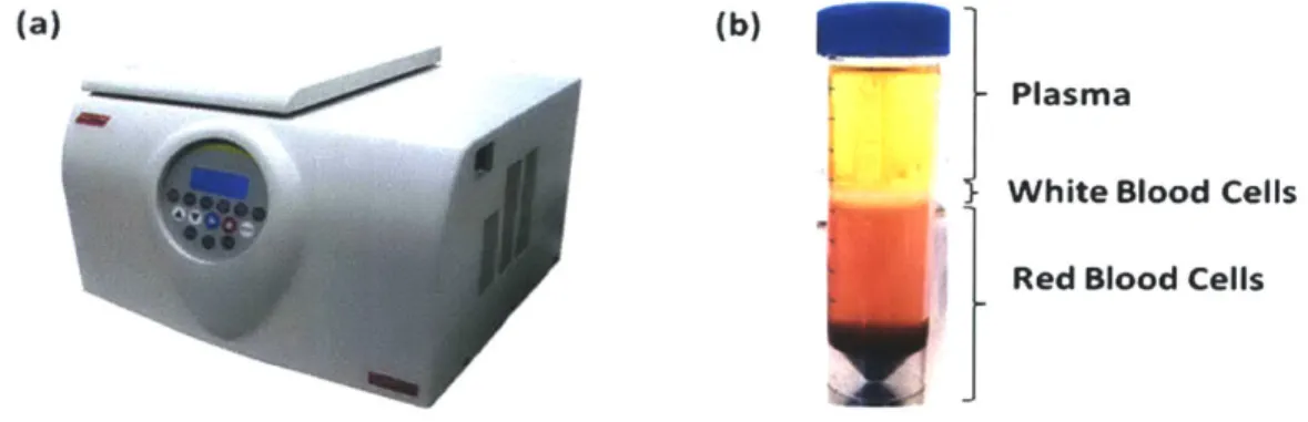
Centrifugation: Often used as the first step in preparation of biological samples, centrifugation has established its position in the clinical and research settings as one of the most instrumental tools for separation of bioparticles on the basis of size and density. Sophisticated ultracentrifuge machines today can generate centrifugal forces on the order of lx106g, thereby expediting sample processing and increasing resolution of bioparticle detection on the basis of size and relative density difference of the bioparticle and the media (Fig. 2-la). The method of centrifugation accelerates the process of sedimentation of various cellular components in the sample and allows concentration of bioparticles with similar size and density in "bands"(Fig.
2-1 b). Improvements over this initial principal have been achieved by using density enhancing media such as (1) Ficoll (a polysaccharide media used for separation blood into its cellular components) and (2) Percoll (a coilloidal silica media used for separating cells, viruses and organelles), and sugar media such as sucrose.
(a) (b)
Plasma
White Blood Cells
Red Blood Cells
Fig. 2-1 (a) Modem day ultracentrifuge (b) Bands of different components of blood after ultracentrifugation
Size Based Filtration: Size based filtration using porous surfaces is one of the most commonly used methods to separate mixture of bioparticle populations based on size and shape differential and when the biomolecular properties of the cells are not well known. Flowing a sample through the device bearing the porous surface, bioparticles larger than the pore size are unable to pass
through the surface and get retained on the surface, whereas the smaller sized bioparticles pass through with ease (Fig.2-2a). Due to operational ease and its scalability, size based filtration has been utilized in large scale industrial applications such as separation of bacteria and viruses from water in water [1] and colloidal particles in coal slurries [44], and clinical applications such as toxins from blood in hemodialysis [2]. One major disadvantage of this configuration of filtration is the rapid deterioration of the device performance due to blocking of pores as a consequence of particle retention [I]. We will discuss the mechanisms behind fouling and blockage of these pores in Chapter 4 and discuss ways to assuage it.
(a) PIe"(C)
Moroaftmon vir us fuero L r NUin o o0tra
ComponwW knact CU VirusS Protos av~ on. Amino aods
teta~~ by G" dsOVU Amino awts Suws mmbrane Bicterta Antiebotics Slt
Membrn
Corp CoIoids ProeIng Ammo acid So** Vter
VOnSg 8~ ~ Anftai W&or
s
J
QueerFig. 2-2: (a) Comparison of removal characteristics of different pressure driven membrane processes [1] (b) Large scale industrial modules containing porous surfaces for removal of bacteria from water [1] (c) Modem day hemo-dialysis machine for removal of toxins from blood using 15 nm porous surface [2]
2.2 Microscale bioparticle separation techniques based on physical
characteristics
Use of microfabrication techniques in designing devices over the past few decades has opened up possibilities to exploit optical, dielectrophoretic, acoustic and fluidic forces, , which become relevant and powerful on the length scales of the bioparticle. These forces allow accurate manipulation of the local bioparticle environment down to the single particle level. Although
selective, weak nature of some of these manipulative forces limits throughput of sample processing.
Optical manipulation: Optical forces provide a precise, non-contact and contamination free method to identify and select cells from a mixture. The most common technique utilized using this principle is optical tweezers where a focused laser confines dielectric particles in a 3
dimensional environment and imparts attractive or repulsive forces based on the mismatch of the refractive indices [45, 46]. Manipulation of bioparticles from a few angstroms to ten's of microns is possible using this technique.
Dielectrophoretic manipulation (DEP): Dielectrophoretic manipulation of cells is
analogous to optical forces. The dielectrophoretic manipulation force depends on the clausius-mossotti factor, which takes into account the dielectric constants of the bioparticle and the surrounding media in a non-uniform magnetic field that imparts attractive or repulsive forces. The phenomenon was first described in the 1950s by Henry Pohl and since has been utilized by many groups to sort cells. Use of microfabrication techniques allow fabrication of electrodes of various materials that generate well controlled non-uniform electric fields. One such example is the use in a microcytometer where an array of electrodes use dielectrophorretic forces to hold the cells in place as the surrounding media flows by and the optical system luminiscently
interrogates the held particle for identification [47]. These forces have also been used to pattern and concentrate bioparticles ranging a few microns upto ten's of microns [3, 48, 49].
(a) (b)
Microchannel (top)
v v v. v. v V
Fig. 2-3: (a) Schematic of the interdigitated electrodes and DEP forces with respect the sample flow (b) fractionation of tumor cells and other blood components on the DEP chip [3]
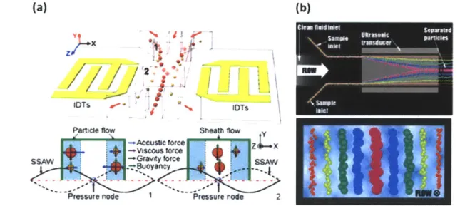
Acoustic manipulation: Acoustic sorting provides yet another method for bioparticle sorting, concentration and patterning by application of externally controllable field [50-52]. In this method, ultrasonic standing waves produce stationary pressure gradients at well defined intervals (nodes) which in liquid medium imparts radial forces to position cells at specific intervals i.e. at the nodes. Concerns over cell due to the radial force and rise in temperature have been raised. However, a recent study by Johanson shows that the amount of force on the bioparticles is ~ 0.5
nN, which is similar to the forces applied using optical and dielectrophoretic forces [53].
Additionally, acoustic forces provide a higher continuous throughput over the optical and dielectrophoretic external fields.
(a) (b)
Particle flow Sheath flow
--Accustic force Z X
-Viscous force
ssaw l Gravity force SheatA W~- -.
Fig. 2-4: (a) Schematic illustrating the principle of acoustic separation by standing surface acoustic waves (SSAW) generated using interdigital transducers (IDT). The varying acoustic forces repositions the larger cells closer to the channel center and smaller cells farther from the center (b) Cells of varying sizes align at distinct positions across the microchannel cross-section based on the acoustic primary radiation force experienced.
Fluid force manipulation: One of the biggest advantages of miniaturization of the existing macro scale cell sorting principles is in manipulation of fluid forces. Laminar flows simplify the Navier-Stokes equations and therefore allow understanding and control of bioparticles in
(a) (b)
Rastdom Pat tel
Small Particle Large Particle i""*"
Focused to Sogre Silberberg
~ annulus
Posts Streamlines
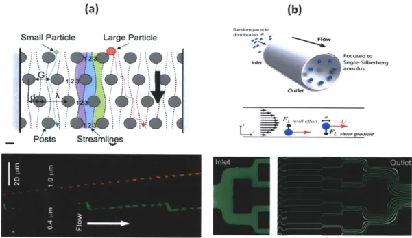
Fig. 2-5: (a) Top schematic shows asymmetric obstacles separating out particles of different size. The bottom figure shows separation of 0.4 pm and 1 pm beads and the respective
trajectories. (b) Top schematic shows the focusing of particle in an annulus. The middle figure illustrated the different forces that determine the eullibrium position of focusing and the bottom figure shows focusing of fluorescent fluid in the microfluidic channels.
Deterministic hydrodynamics make use of low Reynolds number laminar flows (Re<<1) in microfluidic devices. The approach makes use of the asymmetric bifurcations which act as obstructions to the particle in the flow direction (Fig. 2-5a). Based on the size and deformability, separation of RBC's, WBC's, bacteria and solid latex particles have been achieved [54, 55]. In contrast to the low Reynolds number regime used for deterministic lateral displacement where viscous forces dominate over inertial forces, for large Reynolds number ( Re > 1), the vice versa is true. These conditions can be achieved at high flow rates, which enable high throughput processing of samples. These inertial forces tend to push or 'focus' the particles in the channel to equilibrium positions which are determined by Reynolds number, ratio of the particle diameter to channel dimensions and the shape of the particles (fig. 2-5b). Several groups have studied this phenomenon and reported the optimal regimes under which this focusing is high quality [56-58]. Applications of inertial focusing have been used in making micro-scale flow cytometers [59].
2. 3 Separation of bioparticles based on specific biomolecular
recognition
Separation using specific biomolecular recognition ("affinity chromatography") exploits use of unique markers on surfaces of cells of interest. In contrast to the purely physical methods of separation, this technique is highly specific and allows differentiation between cells that are otherwise similar in shape, size and density. Selected complimentary molecules identify the surface markers on target cells by forming biochemical bonds. Various methods have been devised in order to leverage this technique identifying and sorting target cells in solution (FACS and MACS) or on a fixed substrate. Some of the most famous ones are discussed in this section.
Flow activated cell sorting: Fluorescence activated cell sorting (FACS) is widely used in laboratory and clinics. Due to its high sensitivity and mature technology, FACS has become the technique of choice to use commercially [60]. The target cells are focused using sheath flow around the sample injection port to file the cells in the sample within a confined region. The cells are identified via the fluorescent markers tagged onto the complimentary molecules that bind to the surface markers or cytosolic proteins (Fig. 2-6a). The detector in the FACS detects the presence or absence of the fluorescent signal from each cell and records it [4]. Whereas there are several advantages to FACS some of the limitations include clogging, contamination, cell
viability and the expensive nature of the instrument. In order to alleviate some of the above mentioned disadvantages, various groups have developed a microfluidic versions of flow cytometers. One typical format of a p-flow cytometer is the T-junction design where, similar to the original FACS, sample is injected through one port and the sheath flow provides a narrow band of ordered cells which can be interrogated one at a time by the detected. Another variation is generation of droplets that encapsulate cells in order to preserve cells from excessive shear and maintain viability (Fig. 2-6b). Besides, portability, cheap cost and ability to parallelize these devices to increase throughput, microfluidics reduces the drag experienced by the cells due to droplet switching compared to flow switching in its macro counterpart [61].
A
- "put + 0 * 0 0 0 0 Buflr -~ * 4- Buffew Wasie3I
Fig. 2-6 (a) FACS schematic illustrating the principle of FACS (b) Variation of the original
FACS principal where droplets are generated encapsulating cells are generated to preserve cells from excessive shear at high flow rates [4].
Magnetically activated cell sorting: A variant to FACS is Magnetically Activated Cell Sorting (MACS), where magnetic beads instead of fluorescence, bear the recognition molecule that label the target cells [62]. Once labeled with magnetic beads, the target cells are picked out from the general population by using a magnetic field gradient. One of the advantages of MACS lies in the flexibility of its application in either batch or continuous processing modes on large scales. Batch processing involves placement of magnets next to a column containing ferromagnetic material where alternating presence and absence of magnetic fields collects the cells [63]. In
continuous processing, a quadrapole magnet is placed next to liquid columns and cell solution flows through the column. Cells attached to magnetic beads get deflected, whereas the others flow straight through [64]. Similar devices are also implemented in microfluidic formats. These microfluidic MACS devices can be broadly classified into two categories: active and passive traps. In active traps, electrical power is used to generate the desired magnetic field
B+
TFACS e-up
characteristics through on-chip electromagnets (Fig. 2-7a). In contrast, a passive trap uses a permanent magnet, with on chip iron or nickel elements acting as field gradient concentrators (Fig. 2-7b) [65, 66]. Advantages to MACS include the possibility of collecting large number of
target cells at the same time and low cost. However, some of the drawbacks include time consuming and sensitive process of labeling the cells with magnetic beads, low sensitivity and removal of unbound beads [16].
a
b
-t- -m----
---Fig. 2-7 (a) Active method of magnetically activated cell separation using on chip fabricated coils [5] (b) Schematic of passive MACS using an external magnetic to deflect magnetically
attached cells [6].
2.4 Immunochromatography separation using microfluidic devices
Use of specific cells through biomolecular recognition has recently become popular due to the recent developments in the field of microtechnology, which have opened up avenues for studying chemical and biological samples in microfluidic devices, and have started playing important roles in tissue engineering, neurobiology, cell biology and cell sorting. Sensitivity ofimmunochromatography is increased by the use of microfluidic devices, where
microenvironments can be controlled precisely in order to facilitate the biochemical reactions between the complimentary molecules. In contrast to capturing target particles in solution like in FACS/MACS, specific cell capture can be achieved by immobilizing complimentary molecules on the solid surfaces of the microfluidic devices. By controlling the fluidic forces in the
the general population. This methodology has several advantages over the FACS or MACS method of separation using immunochromatography. Firstly, capturing cells on microfluidic solid surfaces does not require pre-mixing of the samples with labels such as magnetic beads and fluorophores. Secondly, Capturing cells on solid surfaces allows for simple addition of
subsequent steps for cell lysis, detection and amplification. Thirdly, expensive and bulky
components such as lasers and permanent magnets are not required. Lastly, being able to control the fluid dynamics in microfluidic device allows greater reliability in results.
Within a microfluidic device several factors such as shear stress, surface topography and concentration, specificity and concentration of immobilized adhesive molecules as well as the target cell type affect cell adhesion in microfluidic devices. Various groups have optimized functionalization with the adhesive molecules in order to maximize cell capture [67-70]. For all these affinity based microfluidic devices, the sample is processed in two steps. The first step, "capture step", aims at capturing the specific cells, whereas the second step, "washing step", removes the non-specifically bound cells on the surface using a washing buffer solution.
Likewise, models describing flow characteristics of the fluid on cell capture for various device designs have been studied. For example Cheng and colleagues developed a straight rectangular channel device with immobilized anti-CD4 immobilized on the surfaces using silence chemistry. The study demonstrated the capability of the device to separate CD4+ T cells. Optimization of the shear stress under which only CD4+ T cells would stick but not the CD4+ monocytes was characterized in this study (Fig. 2-8a) [71]. However, this device geometry suffers from mass transport problems at high flow rate, which reduce the ability of the target cells to contact the reactive surface. This is a big hurdle in cases where the number of cells in the sample is rare (<100 cells/mL) (Section 2.4). By making parallel channels this problem can be partially
alleviated, however it comes at the cost of increasing real estate and hence larger area over which rare cells need to be detected (Fig. 2-8b). In order to increase the encounter between the target cells and hence the sensitivity of the device, pillars (Fig. 2-8c) [40] and "herringbone"[72] (Fig. 2-8d) like structures functionalized with specific antibodies are built on the microfluidic surface. These devices modify the parallel streamlines in the straight channel and allow greater
interaction of cells with the antibody covered surface. These devices demonstrate ability to capture small numbers of circulating tumor cells from whole blood. However, like the flat
channel devices these devices also suffer from capture of specific cells at low flow rates. In order to alleviate the low flow rates in these devices (< 0.3 mL/hr) parallel channels are fabricated. As microfluidics provide a predictable fluidics environment, Adams. et. al. desgined curvy channels of small dimensions (30 pm x 45 pm) using deen flows to enhance specific cell capture
(Fig. 2-8e) [35] and Yang et. al. designed a combinatorial chip consiting of pillar and herring bone pieces that allow for modified streamlines towards the surfaces even in the laminar flow regime (Fig. 2-8f) [37]. For all of the above mentioned microfluidic devices, the sample is
processed in two steps. The first step involves optimizing for the ideal fluid conditions to capture specific cells. The second step, consists of using a washing buffer to "wash away" all the loosely bound cells on the surface to increase purity of capture.
(a)
(b)
(c)
(d)
(e)
(f)
Fig. 2-8 (a) Schematic of a single straight rectangular microfuidic channel and fluid streamlines. (b) Multiple straight rectangular channels with blood in order to improve throughput (c) SEM of a cancer cell immobilized on an EpCAM coated micro-Silicon pillar (d) Schematic of "herring bone" indentations modifying fluid and particles streamlines to increase interaction with the
antibody coated surface (e) Narrow curved channels fabricated using fluidic forces to capture cells (f) Hi aspect ratio CNT forests ("tiny" pillars) developed in conjunction with the herring bone top to enhance specific cell capture.
2.5
Historical use of Porous Surfaces in Microfluidic Devices
Conventionally, solid materials such as glass, silicon, gold and polymers have been used in microfluidic devices. However, recent developments in rigid substrates such as carbon nanotubes as well as innovations in highly controlled porous membranes and monoliths have inspired construction of devices integrating porous surfaces. Incorporation of porous elements have found applications in cell culture, basic chemotaxis studies, microdialysis, tissue engineering and filtration [73]. In this section, we describe a broad class of porous used for cell separation.
Carbon Nanotubes: Carbon Nanotubes (CNT's) have been used in a wide range of biomedical applications because of their unique electrical, thermal and surface properties and
biocompatibility with biological samples. Application in most of these areas make use of covalent [74] and non-covalent [75, 76] methods of functionalizing biomolecules to the CNT surface. For example, Chen et. al. modify fluid fields by patterned antibody functionalized CNT forests permeable to fluid, to increase "interception efficiency" and specific cell capture
efficiency of various size bioparticles by 6 fold [7]. CNT forests provide an unprecedented increase in surface area while maintaining a high porosity (~99%) because of stable structure formations, even at high aspect ratio (Fig. 2-9 a,b,c). Additionally, CNT fibers exhibit unique
semi-conductive properties and allow label free detection of charged biomolecules by acting as field effect transistors and creating gating effects [77, 78]. CNT's have also been explored as drug delivery vehicles. They possess the unique property of getting internalized by mammalian
cells and have therefore been used for chemical and thermal destruction of cancerous cells [79, 80]. Despite its functional uses, CNT integration into microfluidic devices for specific bioparticle separation at high flow rates remains cumbersome and unreliable due to their brittle nature, involved growth and fabrication, and limited scalability.
b
c
Fig. 2-9 Scanning electron micrographs (SEMs) of patterned VACNT elements (a) A 200pm diameter single post (b) An array of 20pm diameter posts (c) Nanostructure of a VACNT forest
[7]
Monoliths: Porous monoliths have been traditionally fabricated inside microfluidic devices by injecting polymer solutions, which are then polymerized using free radicals and UV initiation. Monoliths with different porosities (30% -70%) can be synthesized by varying the
concentrations of organic solvents, monomers and free radical initiators [81]. Applications of porous monoliths, include size based filtration, efficient mixing, and antibody-based specific bioparticle capture, and are similar to the macro scale chromatography columns using solid supports (Fig. 2-10). Even though monoliths provide an easy method for forming random porous structures inside microfluidic devices, diversity in porosity and flow dynamics lead to
considerable variability in specific cell capture from device to the other.
Fig. 2-10 Scanning electron micrograph of a porous monolith formed inside a microfluidic channel using UV initiation.
Porous membranes: Membranes are the most widely used porous surface in microfluidic devices due to ease of integration, scalability, low cost and a large range of selection of
commercial "off the shelf' application specific surface chemistries. Briefly, two kinds of porous membranes are commercially available. Track etched membranes are formed when high energy ionic particles are bombarded through polymers like polycarbonate, Teflon etc and create through holes in the substrate (Fig. 2-1la).The second type of membranes are the mesh membranes with interwoven fibers. These membranes allow fluid to pass through normally as well as tangentially and are usually thicker than the track etched membranes (Fig. 2-11 b). These porous surfaces allow passage of fluid normal to the surface through these holes. Successful incorporation of membranes in microfluidic devices requires leakage free integration. While most microfluidic devices use "glue, alignment and clamp" method [82], photochemical methods have also been developed to achieve constructs that can withstand pressures greater than 200 kPa without leaking or bursting [83]. De Jong et. al. provide a comprehensive review of how to select a membrane focusing on the material, structural type and integration techniques [73]. These
integration techniques have opened possibilities for pre-concentration, purification, microdialysis, chemotaxis and vascularization studies over a long period of time using microfluidics [73]. Even with the advent of other exciting applications mentioned in previous
sections, size based filtration of bioparticles remains the most common use of porous membranes in microfluidics. For example, Kim et al. [84] integrate different functions on a microfluidic device by removing of cells from blood, separating of HDL, and signal generation on a enzyme embedded membrane by using multiple membranes. However, like other size based separation methods described in section 2.5, the filtration achieved with porous membranes does not give specific particle selection.