V\
ALTERNATIVE DESIGN CONCEPTS FOR THE ELECTRON TO
PHOTON CONVERTER IN THE ACCELERATOR BASED
PRODUCTION OF TECHNETIUM-99M
BY
JESS L. IVERSON
B.Sc., NUCLEAR ENGINEERING
(1995)
UNIVERSITY OF ARIZONA
SUBMITTED TO THE DEPARTMENT OF NUCLEAR ENGINEERING IN PARTIAL FULFILLMENT OF REQUIREMENTS FOR THE DEGREE OF
MASTER OF SCIENCE IN NUCLEAR ENGINEERING
AT THE
MASSACHUSETTS INSTITUTE OF TECHNOLOGY
Ai
.8
;
AUGUST 1997
© MASSACHUSETTS INSTITUTE OF TECHNOLOGY 1997. ALL RIGHTS RESERVED.
SIGNATURE OF AUTHOR..
CERTIFIED BY...
READ BY
ACCEPTED
BY...
ACCEPTED BY......
DEPARTMENT OF NUCLEAR ENGINEERINGAUGUST 20, 1997
...
PROFEOR LAWRENCE M. LIDSKY THESIS SUPERVISOR
DR. RICHARD C. LANZA THESIS READER
·... ....
/
i' I JEFFEY FREIDBERGCHAIRMAN, DEPARTMENTAL COMMITTEE ON GRADUATE STUDENTS
ALTERNATIVE DESIGN CONCEPTS FOR THE ELECTRON TO
PHOTON CONVERTER IN THE ACCELERATOR BASED
PRODUCTION OF TECHNETIUM-99M
BY
JESS L. IVERSON
SUBMITTED TO THE DEPARTMENT OF NUCLEAR ENGINEERING ON AUGUST 20,
1997,IN
PARTIAL FULFILLMENT OF THEREQUIREMENTS FOR THE DEGREE OF MASTER OF SCIENCE IN NUCLEAR ENGINEERING
ABSTRACT
The photonuclear production of radioisotopes using electron LINAC bremsstrahlung sources offers an industry alternative to reactor and ion beam production methods. One such method under development is the utilization of the Giant Dipole Resonance in the
(y,n) reaction cross-section. This method is being studied for use in the production of
9 mTc from enriched 100Mo by electron beam induced bremsstrahlung photons. Of primary concern to any radioisotope production system is the specific activity it is able to create of the radioisotope. In a photoneutronic production system maximizing the number of GDR photons on a given target increases the specific activity. Proper design and optimization of the electron-to-photon converter maximizes the number of GDR photons. This study examines some alternative types of converter design. MCNP is used to predict isotope yields and energy deposition in the converter assemblies and an Excel Spreadsheet is used to analyze the heat-transfer capabilities of the systems. Optimized designs are presented for the different types of converters studied. A radiantly cooled converter is presented as a low-yield design, while a circulating loop of molten lead is analyzed for use in a high-yield system.
Thesis Supervisor: Lawrence M. Lidsky
Title: Professor of Nuclear Engineering
Thesis Reader: Richard C. Lanza
ACKNOWLEDGEMENTS
I would like to thank my wife, Terri, for all of her love and understanding during
the time I have been working on my thesis. Without her support I'm quite sure that this would not have been finished. I know that I have been hard to live with at times. Thanks for putting up with me. The computer is yours anytime you want to use it.
I would also like to thank Professor Lidsky and Dr. Lanza for their help and
patience during this time. I realize that things have been rushed here at the end and for that I would like to apologize. Thanks for helping me to complete this document.
Thanks also go to my brother Erik for his many words of encouragement and his late night proof-reading. Without which I'm not sure where I'd be.
Finally, I would like to thank my Father and late Mother. For it is all of their love and encouragement that was able to get me here in the first place.
TABLE OF CONTENTS
1. INTRODUCTION ... 8
1.1 PHOTO-PRODUCTION OF 99 TC... 11
1.2 ELECTRON-PHOTON CONVERTER ... 13
2.0 CONVERTER DESIGN STRATEGY ... 15
2.1 T HEORY ... 15
2.2 TYPES OF CONVERTER DESIGNS TO BE CONSIDERED ... ... 17
2.2.1 RADIANTLY COOLED CONVERTER ... 18
2.2.2 MOLTEN LEAD CONVERTER ... 20
2.3 COMPUTER M ODELING ... 21
2.3.1 ELECTRON-PHOTON TRANSPORT ... ... 21
2.3.2 HEAT TRANSFER M ODEL ... ... 23
3.0 PMHX TUNGSTEN SLUG BASELINE CASE ... 28
4. RADIANTLY COOLED CONVERTER ANALYSIS ... ... 30
4.1 SINGLE INCLINED PLANE OF TUNGSTEN... 30
4.1.1 FOUR BASIC M ODELS... 32
4.1.2 VARIATION OF PLATE THICKNESS... 35
4.1.3 VARIATION OF ELECTRON BEAM ENERGY ... ... 38
4.1.4 OPTIMUM SINGLE INCLINED PLANE CONVERTER DESIGN... ... 41
4.2 MULTIPLE INCLINED PLANES OF TUNGSTEN ... ... 42
4.3 SINGLE CONE OF TUNGSTEN... 43
4.4 SYSTEM OPTIMUM DESIGN AND LIMITATIONS ... ... 45
5. MOLTEN LEAD CONVERTER ANALYSIS ... 46
5.1 BASIC DESIGN ... 46
5.2 MCNP ANALYSIS AND DESIGN PERFORMANCE ... 49
5.3 OPTIMUM MOLTEN LEAD CONVERTER DESIGN ... ... 53
6. MOLTEN LEAD CONVERTER SYSTEM DESIGN ... 55
6.1 BASIC CIRCULATING LEAD LOOP DESIGN... 55
6.2 HEAT EXCHANGE SYSTEM ... 56
6.3 ELECTROMAGNETIC FORCE PUMP ... 60
6.4 MINOR SUBCOMPONENTS OF LEAD LOOP ... 63
6.4.1 STARTUP HEATING SYSTEM ... ... 63
6.4.2 LEVEL CONTROL AND SYSTEM MONITORING... 64
7. CONCLUSIONS ... 66
APPENDIX A ... ... 68
M ODEL 1: PHM X SLUG ... 68
MODEL 2: SINGLE INCLINED PLANE ... 69
MODEL 3: MULTIPLE INCLINED PLANES ... ... 70
MODEL 4: CONE MODEL ... 71
MODEL 5: MOLTEN LEAD FLOW MODEL ... 72
APPENDIX B ... 73
RADIANT M ODEL ... 73
LEAD FLOW M ODEL... 74
LIST OF FIGURES
FIGURE 1: GIANT DIPOLE RESONANCE FOR MOLYBDENUM- 100 ... 11
FIGURE 2: MAXIMUM BEAM ENERGY VERSUS MAXIMUM BEAM CURRENT... 13
FIGURE 3: SURFACE AREA REQUIREMENTS FOR RADIANT HEAT TRANSFER... 19
FIGURE 4: MCNP TALLY CARD FOR DETERMINING MOLYBDENUM YIELD ... 22
FIGURE 5: TEMPERATURE DEPENDENT PROPERTIES OF TUNGSTEN... 26
FIGURE 6: YIELD FOR THE PHMX SLUG MODEL ... ... 29
FIGURE 7: RADIANT HEAT TRANSFER FROM INCLINED SURFACE ... 30
FIGURE 8: BASIC SYSTEM DESIGN FOR RADIANTLY COOLED CONVERTER ... 31
FIGURE 9: YIELD FOR THE OPTIMUM INCLINED PLANE MODEL ... 41
FIGURE 10: TEMPERATURE PROFILE FOR OPTIMUM SINGLE PLATE CONVERTER ...42
FIGURE 11: BASIC DIAGRAM OF MOLTEN LEAD CONVERTER SYSTEM ... 47
FIGURE 12: THE CONVERTER SECTION OF THE MOLTEN LEAD LOOP... 48
FIGURE 13: THE YIELD FOR THE OPTIMUM MOLTEN LEAD CONVERTER ... 53
FIGURE 14: CROSS-SECTION OF LEAD TO WATER HEAT EXCHANGER... 57
List of Tables
TABLE I: PHYSICAL PARAMETERS FOR 4 BASIC RADIANT TRANSFER MODELS... 32
TABLE II: ENERGY BALANCES FOR THE BASIC MODELS ... 34
TABLE III: SUMMARY OF RESULTS FOR 4 BASIC MODELS ... 35
TABLE IV: RESULTS FOR VARYING THICKNESS ON 5-CM CONVERTER PLATE ... 37
TABLE V: RESULTS FOR VARYING THICKNESS ON 10-CM CONVERTER PLATE... 37
TABLE VI: RESULTS FOR VARYING ENERGY ON 5-CM CONVERTER PLATE... 39
TABLE VII: RESULTS FOR VARYING ENERGY ON 10-CM CONVERTER PLATE ... 39
TABLE VIII: RESULTS FOR VARYING ENERGY ON OPTIMIZED 5-CM PLATE ... 40
TABLE IX: RESULTS FOR VARYING ENERGY ON OPTIMIZED 10-CM PLATE... 40
TABLE X: RESULTS FOR TWO-PLANE MODEL... ... 43
TABLE XI: ENERGY BALANCE FOR INITIAL LEAD CONVERTER MODEL ... 50
TABLE XII: RESULTS FOR VARYING ENERGY ON MOLTEN LEAD CONVERTER ... 51
TABLE XIII: YIELD FOR RANGE OF LEAD CONVERTER MODELS... 52
TABLE XIV: CURRENT WEIGHTED YIELD FOR RANGE OF LEAD MODELS ... 52
TABLE XV: MODEL OF HEAT TRANSFER FROM LEAD TO CHANNEL WALL... 57
TABLE XVI: MODEL OF HEAT TRANSFER FROM STEEL BUFFER TO WATER ... 58
1.
INTRODUCTION
Every year, radioisotopes (radioactive isotopes) are used in millions of industrial,
scientific, and medical applications[10]. These uses range from tracking the dispersion of
chemicals in the water aquifer to identifying tumors in cancer patients. In many cases
there simply is no other way to gather the information gained from radioisotope testing.
For this reason a constant, reliable source of high-grade radioisotopes is of utmost
importance.
One of the most important uses of radioisotopes is in the field of medical testing.
One in three hospitalized patients undergo some type of test or treatment involving
nuclear medicine. Radioisotopes are used in almost 36,000 imagining procedures and
29,000 laboratory tests every day in the United States alone. Over 80% of these tests
utilize 99mTc[3]. When combined with a variety of pharmaceutical carriers, 99mTc can be
used to study nearly every major system in the human body. For instance, 99mTc
pertechnetate is used to study the thyroid and salivary glands, while 99mTc exametazine is
used to study the brain. It is even possible to tag red blood cells with 99mTc to study
gastrointestinal bleeding and the chambers of the heart.
99mTc has a half-life of 6.03 hours. Normally, this would make a radioisotope
very difficult to transport for use anywhere other than at its production facility. However,
99mTc is actually the daughter product of 99Mo. The 99Mo decays with a half-life of 66
hours to the 99mTc. This gives a relatively large time frame for the
molybdenum-technetium mixture to be transported for use. Typically the mixture is packaged in
football sized "generators". Contained in the generators are chromatographic columns in
saline solution over the chromatographic column which is then mixed with the appropriate pharmaceutical carriers. The 99mTc decays primarily (89.1%) by emitting a
low energy (140.5 keV) gamma ray. This decay scheme results in delivering a fairly low
dose to the patient, while still having a sufficient energy and reasonable time frame for
detection outside of the body.
Most commercial radioisotopes are produced either by nuclear reactors or by
heavy particle accelerators[8]. By far, the majority of radioisotopes are produced by
fission product separation from highly enriched uranium (HEU) targets placed in nuclear
reactors. This separation process is extremely difficult and expensive. Complex remote
handling facilities must be used to safely extract the various useful isotopes from the
highly radioactive HEU targets. The majority of the processing uses a variety of
chemical reactions to separate the different isotopes from one another; this generates a
large volume of chemically and radiologically dangerous waste.
However, there are also a number of advantages to producing radioactive
isotopes, including 99Mo, in nuclear reactor cores. Originally, 99Mo was produced
commercially by neutron absorption in natural molybdenum or enriched 98Mo. The
disadvantage of this type of production was that it led to fairly low specific activities for
the 99Mo, in the several Curie/gram range. Therefore, in order for the saline solution to
extract reasonable amounts of 99mTc, the generators shipped to the hospitals were quite
large. These larger generators required a significant amount of shielding, which made
them difficult to transport from the production facility to the end-user. On the other hand
reactor produced fission product 99Mo has activities on the order of 104 Curie/gram. In
would damage the chromatographic columns it was being transported in. This high
activity allowed the generators to become very compact. With shielding the generator is
approximately the size of a football.
Currently, 99Mo production is reaching a crisis point in North America. The only
facility producing 99Mo in useful quantities is the near 40-year-old NRU reactor in Chalk
River, Ontario. The reactor is scheduled to be shutdown in the year 2000 and recently
labor problems and aging equipment at the plant have caused numerous unexpected
temporary shutdowns. The NRU reactor is scheduled to be replaced by the Maple-10
isotope reactors in Canada. There are also plans for the conversion of an existing
Department of Energy reactor to the production of 99Mo at Oak Ridge National
Laboratory. However, there are no guarantees as to when and if these replacement
reactors will reach production capacity. Assuming they are replaced, the new reactors
will continue to use HEU targets, and therefore the problem of dealing with high-activity
fission product waste will persist. This situation is obviously unstable, and it is readily
1.1 PHOTO-PRODUCTION OF 99Tc
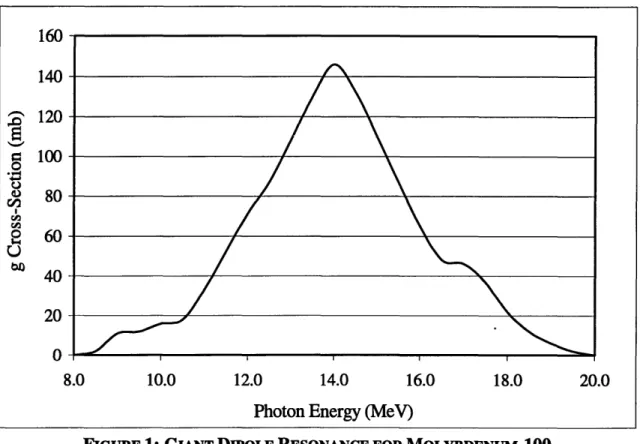
Currently research is being done on the use of electron beams in the production of radioisotopes. The reaction of interest explored in this study is the photoneutronic (y,n) reaction in l00Mo initiated by electron beam induced bremsstrahlung. This reaction results in the production of 99Mo, the parent of 99mTc. Over most of the energy spectrum the
cross-section for this reaction is very low, but there is a resonance in the photon
absorption cross-section, known as the giant dipole resonance (GDR), which occurs
between 8 MeV and 20 MeV for '"Mo. Figure 1 below shows the'cross-section of the
GDR for 'lMo over its energy range.
FIGURE 1: GIANT DIPOLE RESONANCE FOR MOLYBDENUM-100
If a photon beam is concentrated in this energy region it is possible to achieve very high
reaction rates, subsequently creating high specific activities of 99Mo. The utilization of
this type of reaction is not limited to the production of 99Mo. The giant dipole resonance 160 140
$^
120 a 100 4 80 R 60 U40
200 -8.0 10.0 12.0 14.0 16.0 18.0 20.0is a result of the forces caused by the interaction of photons and neutrons in the atomic
nucleus, and therefore exists in some capacity for all isotopes. The peak energy of the
resonance roughly decreases as the atomic mass of the nuclei in question increases. The
full width at half-maximum of the peak remains fairly constant for any resonance, while
the total area of the resonance increases with atomic mass. Therefore, this type of
reaction is much easier to take advantage of with heavier elements.
The difficulty in using this production technique for other isotopes is not so much
a problem in nuclear science as it is in chemistry. Since the technique produces fairly
low specific activities, the daughter nuclei must be easily separable from the parent
nuclei. This is true in the case of 99mTc. The enriched 1'OMo target is exposed to the
photon beam and a portion of it is transformed to 99Mo. Technetium and molybdenum
are then easily separated, either in an ion exchange column or in a thermal sublimation
system. Therefore, as the 99Mo decays to 99mTc it is easily removed. After economically
optimal amounts of the radioisotope have been used, the unconverted enriched 1°°Mo is
returned to the production facility to be recycled. For this type of system to be useful in
the production of other radioisotopes a similar separation scheme must be available.
The photon beam used for this reaction is provided by the conversion of high
energy accelerated electrons to bremsstrahlung photons in a high-Z material, such as
tungsten or lead. The high-Z material portion of the system is referred to as the
converter, since it converts electrons into photons. The electron beam is generated using a
LINAC. Typical LINACs are capable of operating over a range energies, with the
maximum beam current at any energy determined by the power supply and design of the
Ventures, is designed to be operated at 450 mA current at a 0.001 duty factor for 50 MeV
Electrons, which would provide a average beam power of 24.5 kW. This LINAC can be
set to any current below the line, shown in Figure 3 below, for electron energies between
28 MeV and 68 MeV.
25 30 35 40 45 50 55 60 65 70
Electron Energy (MeV)
FIGURE 2: MAXIMUM BEAM ENERGY VERSUS MAXIMUM BEAM CURRENT
So while it is possible to use the accelerator to produce 65 MeV electrons, the current
would be so low that almost nothing can be done with the beam. A large portion of the
electron beam energy will ultimately be deposited in the electron-to-photon converter.
1.2
ELECTRON-PHOTON CONVERTERThe design of the electron-photon converter can have a drastic effect on the
efficiency of this type of isotope production system. By increasing the photon beam on a
given target the specific activity of the end product can be substantially increased. 1000
800
600
400
However, this also has the effect of increasing the amount of energy deposited in both the
converter and target. Therefore, these components must be designed to optimize their
heat removal characteristics and to minimize the unnecessary energy deposited in them.
The object of this study is to optimize the design of the electron-photon converter and to
2.0
CONVERTER DESIGN STRATEGY
2.1 THEORY
One of the most important design parameter in a radioisotope production system is yield, which is the amount of the original target material converted into the desired isotope. The other is the specific activity, which is the decay rate per unit mass in the
target. The yield in a 99Mo photo-production system is determined by two factors. The
first factor is the enrichment of the o10Mo in the target assembly. The second factor is the
number of photons incident on the target whose energy is within the range of the Giant
Dipole Resonance for the (y,n) reaction in 'loMo. In turn, the yield is limited by the rate
at which heat is deposited in the converter and target assemblies. The heat deposition
rates in these systems can get very high; so high as to melt the tungsten or molybdenum
contained in them within a few seconds without cooling.
The photon flux on target is determined by the current of the electron beam and
the conversion rate of electrons to bremsstrahlung photons in the converter. The energy
of the electron beam and the attenuation characteristics of the converter and target
determine the photon spectrum, and therefore the number of photons that fall within the
Giant Dipole Resonance region. Clearly the goal is to maximize the flux on target of
photons in the energy range of the Giant Dipole Resonance. This is achieved by using a
high-Z material for the electron-photon converter. However, high-Z materials are also
quite efficient at absorbing photons, so the design must be such as to minimize the
shielding effects. The optimal thickness for photon production is approximately half the
electron range in the material, so that a residual electron beam is mixed with the photon
must be minimized. The electron beam produced by the accelerator is essentially
mono-directional. However, the photons generated in the converter are not, although the
high-energy photons of interest are primarily forward scattered. Therefore, it is important to
minimize the distance between the converter and target while still leaving room to
remove the residual electron beam by magnetic deflection or absorption in a material
relatively transparent to GDR photons.
In addition to the optimizing the conversion rate of electrons to GDR photons, the
flux on target may also be improved by increasing the current of the electron beam.
However, this has the effect of increasing the amount of heat deposited in the
electron-photon converter and the molybdenum target. Therefore, the current may only be raised
to a certain level. This level is set by the maximum heat removal characteristics of the
converter and target systems.
Therefore, the system is optimized by designing it in such a way as to maximize
the conversion of electrons into photons in the Giant Dipole Resonance energy range and
its heat transfer characteristics. The beam current may then be increased until the cooling
system reaches its upper limitations. A series of analysis were performed with a variety
of converter designs to observe trends in system performance. These trends were then
used to determine system design parameters. Finally, consideration was taken for the
complexity of the system in both use and construction. For a production facility to be
2.2
TYPES OF CONVERTER DESIGNS TO BE CONSIDEREDThe baseline design for the converter system is a 1-cm long slug of porous
tungsten, equivalent to a 0.35-cm long slug of nonporous tungsten. Forcing helium
through the pores in the metal cools the slug of tungsten. This is.known as a porous
metal heat exchanger (PMHX). This system performs quite well at low to moderate beam
currents and is well proven with years of experimentation to back it. However, it is
incapable of cooling a system at high beam current unless the helium is at an elevated
pressure and flow rate. This would require the use of a complex pumping system for a
gas-to-gas or gas-to-water heat exchanger.
The main theories behind the following conceptual designs are not only the
maximization of heat transfer and GDR photon flux on target, but also the simplification
of system design. Simple designs typically translate into higher capacity factors and
system efficiency. For this reason a great deal of effort has gone into engineering
electron-to-photon converter designs that have no moving parts. Two overall design
concepts were chosen for this study. The first design was chosen for its simplicity, the
2.2.1 RADIANTLY COOLED CONVERTER
A radiantly cooled converter is very attractive for the simple fact that it has no
moving parts. Since tungsten's melting point is at 3660K the converter is able to operate
at a very high temperature (2500K-43000K), which allows the radiant heat transfer to
become very efficient. The primary disadvantage of the radiantly cooled system is the
amount of surface area on the converter required for adequate head transfer to take place.
By using the basic laws of radiant heat transfer, a conservative model of the system can
be generated. This simple model is based on the assumption that the heat deposition is
uniform across the entire slab. In the actual system the heat is deposited only in the path
of the beam, which appears as an elongated oval over the length of the slab. Therefore,
the area calculated by this model is of the center oval and not the entire slab. The rest of
the slab acts as a heat sink, but is not considered here to improve the model conservatism.
The conduction of heat from the beam path to the heat sink causes the actual peak
temperature on the slab to be substantially lower (100K-4150K) than the one generated
by this simple model. The basic equation governing the simple radiant heat transfer
model is as follows:
q=e.-o-A-(T s r -T)
Where e = Emissivity of Surface (average for Tungsten = .225)
a = Stephan-Boltzman Constant (5.67E-12 W/cm2K4) A = Surface Area of object (cm2)
Tsur = Temperature of Radiant Surface (K) Ts = Temperature of Surrounding (K)
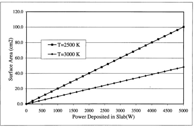
A typical target in this system will have to be able to reject 2000 to 5000 watts of power, or an average of about 3500 watts. Therefore, at a surface temperature of 3000K and a
cm2 in order to reject 3500 watts of power. Figure 4 below shows a comparison of the
required surface areas for different values of heat deposition. The top line represents the
requirements for a surface temperature of 2500K and the bottom for 3000K.
FIGURE 3: SURFACE AREA REQUIREMENTS FOR RADIANT HEAT TRANSFER
For this reason the design of a radiantly cooled target must be centered on maximizing
the surface area available for heat transfer. Three different designs were considered for
the radiantly cooled target. The first design is a singular plate of tungsten placed at a
very shallow angle in the beam bath. By having the beam strike the plate of tungsten at a
shallow angle the area over which the beams energy is deposited is greatly increased.
This has the negative effect of increasing the length and thereby placing the converter at
an average distance further from the converter, lowering the flux on target. The second
design considered was that of multiple plates of tungsten set at opposite angles to one
another. This was chosen because it would increase the surface area of the converter and IZ LU.U 100.0 80.0 60.0 t 40.0 20.0 0.0 0 500 1000 1500 2000 2500 3000 3500 4000 4500 5000
Power Deposited in Slab(W)
it would make the average distance from converter to target more uniform over the beam
cross-section, thereby leveling the flux-distribution over the surface of the molybdenum
target. Finally, a cone shaped model was analyzed. This design was chosen because by
facing the cone in the direction of the beam the point of the cone is placed nearest the
target. Therefore, the small scattering angle, high-energy photons that are generated in
the point have a much higher probability of striking the molybdenum target.
2.2.2 MOLTEN LEAD CONVERTER
A molten lead target was considered for analysis when the heat deposition
limitations of the radiant cooled converter were reached. A molten lead converter has a
number of advantages over the solid tungsten converter, primarily that since the lead is
already a liquid there is no need to worry about melting it. The lead is simply pumped in
a small circulating loop with a lead-to-water heat exchanger. At one point in the loop the
flow is pinched and the walls of the tubing narrowed where the beam will strike. The
heat exchanger is scaled so as to allow adequate heat transfer for the amount of deposited
energy. This makes the lead loop substantially easier to cool than the tungsten target. If
greater cooling of the lead is required the size of the heat exchanger can be increased to
allow for additional heat transfer. Another significant advantage to a lead converter is that
it has a better conversion rate of electrons to GDR photons than does tungsten. The
disadvantage, compared to the radiantly cooled tungsten target, is that a liquid system is
more complex, requiring a pump and heat exchanger. However, if the design uses an
electromagnetic force pump then there are no moving parts in the cooling loop.
Electromagnetic force pumps have been proven to work quite well with liquid lead
systems. By eliminating all moving parts in the system, the opportunities for system
failure are significantly decreased. Preliminary analysis of the molten lead converter
showed a number of advantages over either the PMHX cooled slug or the radiantly cooled slab and it was therefore chosen for the most detailed study, including the design
of an operational system.
2.3
COMPUTER MODELINGTwo different phases of computer modeling were performed for this project,
nuclear interaction and heat transfer. For the radiantly cooled model the capacity of the
design was so tightly linked to the heat transfer characteristics that the models were
performed in parallel so as to asses the viability of various perturbations before extensive
research time was spent on them. For the molten lead converter the nuclear interaction
analysis and heat transfer analysis were performed separately. This is acceptable since it
is possible to simply scale the heat transfer system to the requirements of the loop design.
The computer analysis was performed on a Pentium-200MMX processor based personal
computer.
2.3.1 ELECTRON-PHOTON TRANSPORT
The electron and photon modeling was performed using MCNP (Monte-Carlo
N-Particle) version 4A. MCNP is a time-dependant, continuous energy, coupled
neutron/photon/electron Monte Carlo transport code. By defining a geometric system,
and all materials contained within it, it is possible to model most types of electron,
photon, and neutron interactions. If the tallying system in MCNP is used properly, it is
capable of providing very accurate models of electron and photon transport in the
reactions, because it does not contain the requisite cross-sections. Cross-section data is
available in the physics literature, although it is somewhat difficult to correct for (y,pn)
reactions. The following MCNP tally card can model the photoneutronic reaction rate
due to the (y,n) and (y,np) reactions in a molybdenum target cell:
FIGURE 4: MCNP TALLY CARD FOR DETERMINING MOLYBDENUM YIELD
A tally type 4 generates the average flux of the specified particle type, in this case
photons, over the entire volume of the designated cell per input electron. The E card
divides the tally so that the photon flux in each energy range is determined, i.e., the flux
with energies from 8 to 8.5 MeV, 8.5 to 9 MeV, etc. Each of the energy specific fluxes is
then multiplied by the cross-section for looMo in that energy range. Since flux multiplied
by a cross-section equals the reaction rate, this card can compute the rate at which 99Mo
is produced in the target slug. This tally's results have been verified by experimental
research carried out at the Rensselaer Polytechnic Institute. In this experiment
molybdenum foils were irradiated in a 40 MeV electron LINAC and the induced
activities were within 5% of the values predicted by this tally.
At this point it becomes necessary to define several figures of merit that will be
used to compare the various models during this study.
Yield: This refers to the flux of GDR photons averaged over the molybdenum
slug multiplied by the molybdenum (y,n) reaction cross-sections listed above, thus
F4:P 1
c If cell I is the molybdenum target then Tally Type 4 calculates the photon flux averaged over the c target
E4 8 8.5 9 9.5 10 10.5 11 11.5 12 12.5 13 13.5 14 14.5 15 15.5 16 16.5 17 17.5 18 18.5 19 19.5 20
c The E card divides Tally 4 into the specified energy bins from 8 to 20 MeV
EM4 0 2 11 12 16 18 33 52 71 87 108 130 146 132 110 87 65 48 46 37 22 12 6 2 0
c The EM card multiplies each of the energy bins by the indicated value, in this case the cross-c secross-ction for (yn) and (ynp) reacross-ctions in l00Mo in the respecross-ctive energy bin
giving an averaged (y,n) reaction rate over the molybdenum slug. It should be
noted that the flux of photons is relative to the flux of incident particles, i.e., it is a
percentage of the incident number of electrons.
Current-Weighted Yield: This is simply the yield multiplied by the ratio of the
relevant current for the electron beam to the current of the slug baseline model
(250pA). This value will help to show the difference between various designs in
regards to the beam current at which they can be operated.
Analyzing several tallies produced by MCNP will generate these values. Sensitivity
studies will then be performed to determine optimum designs.
2.3.2 HEAT TRANSFER MODEL
Two spreadsheet-based heat transfer models were used for the analysis of the
converter designs, one for the radiantly cooled converter and one -for the molten lead
converter. Both of these spreadsheets are shown in Appendix B. A spreadsheet-based
model was chosen over the use of a complex heat transfer code for its ease of use. While
the use of a commercial heat transfer code, such as ALGOR or HEATING, may have
given a more detailed analysis, it was determined that this simply wasn't needed for the
goals of the project. A conservative estimate model would accurately predict whether or
not a given system is capable of functioning at operational conditions without destroying
itself. As long as all errors are on the side of conservatism, then a more detailed model
would only show that the system works even better than predicted.
The radiant heat transfer spreadsheet is based on an iterative step approach to
modeling heat transfer in the system. The slab of tungsten is first divided into four
that is 30 cells wide and 50 cells long, thus making each individual cell a very small portion of the slab. Now consider one cell within the grid. The initial temperature of the cell is set to 3000 K, the approximate operating temperature of the tungsten slab. Then the change in the temperature of this cell, due to deposited heat from the electron beam
and various heat transfer modes, is determined. This change is then applied to the initial
temperature for the next iterative step, or:
TI=T2
T1 - AT- OT2=T1 +AT
While this method is primarily for modeling transient heat transfer, it is also quite useful
in modeling combined mode heat transfer problems when the system can be treated as
essentially two dimensional. The problem with combined mode heat transfer problems is
that many times it is almost impossible to analytically solve for the governing equations
of the entire system. This is readily apparent when the radiantly cooled slab system is
considered. The heat deposition of the beam causes a very large temperature gradient
over the surface of the slab. Therefore the radiant heat transfer occurs at very different
rates over the entire surface. This system is very difficult to solve implicitly, but is
relatively simple when the numerical approach is taken. Since the slab of tungsten is so
thin, the temperature gradient over the thickness is negligible. Therefore, it can be
modeled as two-dimensional system.
As stated the primary equation in such a system is:
T2 = T, +AT
Where T1=the cell's initial temperature
AT=the temperature rise due to heat transfer T2=the cell's temperature after AT
To determine the temperature rise in a cell the following equation was used:
AT=
Q
C, p-V
Where Q=the heat transfer into the cell (J) Cp=the specific heat of Tungsten p=the density of Tungsten (19.3 g/cm3) V=the volume of the cell (cm3)
The heat transfer into the cell is then determined by summing the power deposition,
conduction to/from adjacent cells, and the radiant heat transfer:
Q
=
(qBEAM
+
qCOND
-
qRAD)
Tstep
Where qbeam= Power deposited by the beam (W)
qcond= Power transferred to cell by conduction (W) qrad= Power dissipated by cell by radiation (W) Tstep= the time step taken by the spreadsheet (s)
The heat transferred to and from the cell by conduction with the cells surrounding it is determined by the following equation:
(dx dz.d(T -T) dy-dz-(T2 -T) dx-dz-(T3-Tc) dy.dz.(T4-Tc)
qoN =k- + + +(
dy
dx
dy
dx
Where k=conductivity of Tungsten (w/cmK)
dx, dy, dz=respective dimensions of the cell (cm) T1, T2, T3, T4=temperatures of adjacent cells (K) Tc=temperature of cell (K)
The heat dissipated by the cell through radiant heat transfer is calculated by the following equation:
qRAD
=
2
•E'"dx-dy-(TC4-rSUR4
Where E=the emissivity of Tungsten
a=Stephan-Boltzman (5.67E-12 w/cm2K4) Tsur=time step of the iterations (s)
Finally, three of the parameters shown above are temperature dependent and vary
significantly over the temperature range of the tungsten slab. The conductivity, specific
heat, and emissivity all have substantially different values over the range of temperatures
from 1500 K to 3000 K. A linear approximation is sufficiently accurate for our purposes.
Figure 5 below shows these approximations:
1.10 1.05 W 1.00 . 0.95 0.90 0.85 0.80 U.JU 0.27 . 0.24 0.21 0.18 0.15
FIGURE 5: TEMPERATURE DEPENDENT PROPERTIES OF TUNGSTEN
In the actual spreadsheet all three of these calculations are actually combined into a single
larger equation. Therefore, there are only two values for each cell shown on the
spreadsheet, the temperature at the beginning and at the end of the time step.
The spreadsheet model for the molten lead is not as complex as the spreadsheet
for the radiantly cooled target. In fact, the only reason a spreadsheet format was used
was so that individual parameters could be changed and the results be determined without
working through the mathematics by hand every time. This allowed a wide variety of
1500 1700 1900 2100 2300 2500 2700 2900
Temperature (K)
system parameters to be explored in a relatively short amount of time. The majority of equations used in the spreadsheet are the basic formulas governing conductive and convection heat-transfer.
3.0
PMHX
TUNGSTEN SLUG BASELINE CASE
Since the goal of this project is to analyze alternative converter designs, it is necessary to evaluate the initial design. The preliminary design of the converter is based on the use of a 40% porous tungsten slug. The slug is 1 cm in diameter and 0.583 cm long. This corresponds to a thickness of 0.35 cm of solid metal tungsten. Forcing pressurized helium through the porosities from one end of the slug to the other provides heat transfer. The system is operated at a beam energy of 40 MeV and a current of 250 gA, which corresponds to an overall beam power of 10 kW. The molybdenum target will be modeled as a cylinder 1 cm in diameter by 1 cm long and will be placed 5 cm from the end of the converter. The molybdenum target and its placement will be kept consistent for all models to allow accurate comparison of the different designs. The MCNP input deck for the slug converter is given in Appendix A.
The slug converter model has a yield of 2.738+0.033 mb/cm2. Since the current-weighted yield is defined by the PMHX slug case it also has a value of 2.738+0.033 mb/cm2. To put these values in more easily understandable terms, a Yield of 2.738 mb/cm2 corresponds to one 'l°Mo(y,n)99Mo reaction for roughly every 7500 incident electrons. Fortunately, a 20 kW beam of 45 MeV electrons is composed of 2.774x10'5 electrons per second. Therefore, approximately 3.7x 10¹¹ 'Mo(y,n) 99Mo reactions would occur per second in the molybdenum target. While this reaction rate may at first seem very high, it is in fact quite low when compared to the approximately 4.82x10²² atoms of 'OOMo in the target slug. It would take 36 hours of irradiation time to convert 0.0001% of the target from '"Mo to 99Mo. The specific activity corresponding to this irradiation time
is 0.3929 Ci/g. Increasing the yield is one of the largest reasons for exploring alternative
converter designs. Increasing the yield, by increasing the GDR photon flux on target, is
the most direct way of increasing the specific activity of the end product.
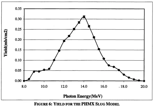
FIGURE 6: YIELD FOR THE PHMX SLUG MODEL
A graph of the yield contribution over the GDR energy range is shown above in Figure 6.
As this graph shows, the energy range from 12 to 16 MeV has the most significant
contribution to the total yield. At the same time the slug absorbs 14.7 MeV out of every
40 MeV electron. This corresponds to an energy deposition rate of approximately 3.7
kW, or 37% of the total beam power. This provides a baseline for the results from the
radiant cooling and lead loop designs to be compared against.
U.J3 0.30 0.25 0.20 0.15 0.10 0.05 0.00 8.0 10.0 12.0 14.0 16.0 .18.0 20.0 Photon Energy(MeV) nr
4.
RADIANTLY COOLED CONVERTER ANALYSIS
4.1
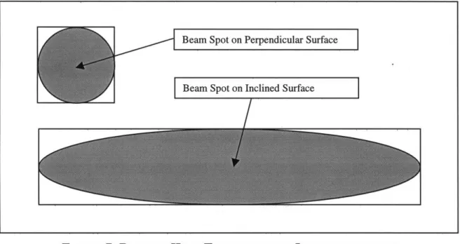
SINGLE INCLINED PLANE OF TUNGSTENThe first design chosen for the radiantly cooled converter was a single plane of
tungsten placed at a very shallow angle in the electron beam path. The thickness of the
tungsten plane is then adjusted so that the electron beam strikes the desired number of
grams per square centimeter. By placing the tungsten plane at such a small angle the
surface area over which the electron beam strikes the converter is greatly increased. This
is illustrated in Figure 7 below.
FIGURE 7: RADIANT HEAT TRANSFER FROM INCLINED SURFACE
This increased surface area makes it possible to cool the target by radiant heat
transfer alone. A single plane was chosen for preliminary study over other radiantly
cooled designs because it does not suffer from the negative effects of a "viewing angle"
for radiant heat transfer. In basic radiant heat transfer it is assumed that heat is being
radiated from a small surface area to an infinite surface area in all directions. This
approximation works quite well as long as the surface area of the heated surface is
Beam Spot on Perpendicular Surface
Beam Spot on Inclined Surface _
several orders of magnitude smaller than the available surface area to radiate heat to. A "viewing angle" must be taken into account when the heat cannot be radiated in every direction due to a surface at the same temperature as the heated surface. Not only does this greatly increase the difficulty of the heat transfer calculations, but it also always has a negative effect on the radiant heat transfer rate. Therefore, it is desirable to avoid designs falling outside the criterion for simple radiant heat transfer.
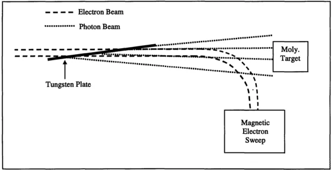
This system is very attractive for its sheer simplicity. With no moving parts there are far fewer chances for something to malfunction or fail during operation. A basic operational system, as shown below in Figure 8, would simply be composed of the tungsten plane, a vacuum container for the slab, and a magnetic sweep to remove the electrons from the beam path before striking the molybdenum slug. The vacuum container would probably be cooled by a flow of water to maintain low temperature, but over such a large surface area a tap fed flow would be sufficient.
FIGURE 8: BASIC SYSTEM DESIGN FOR RADIANTLY COOLED CONVERTER
- - - Electron Beam ... Photon Beam ... ... . ... -- - - -- --- -- --..- -aa.& - - -.--.- · Moly. ... ... ... .T Tungsten Plate
i
4.1.1 FOUR BASIC MODELS
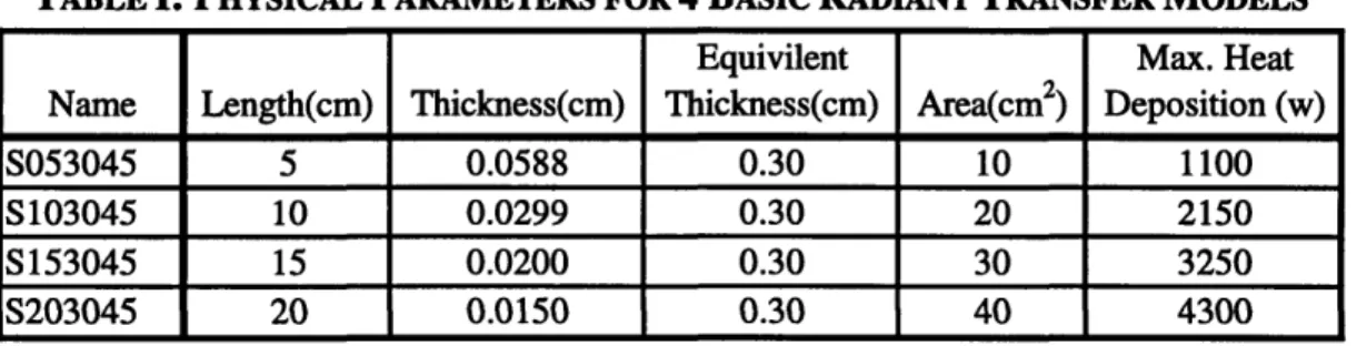
Four basic models were considered in the initial part of this study. Inclined
planes 1 cm wide and with horizontal lengths of 5 cm, 10 cm, 15 cm, and 20 cm where
chosen for analysis. The planes are of the appropriate thickness to give an equivalent
horizontal thickness of 0.30 cm. The maximum allowable heat deposition rate for each
plane is then determined using the formula outlined in section 2.3.2 to maintain its
surface temperature at 3000K. A summary of these design parameters is given below in
Table I. The name for each model is determined by three design factors: horizontal
length, equivalent thickness, and electron beam energy. For instance, S103045 is a
model that has a horizontal length of 10 cm, an equivalent thickness of 0.30 cm, and a
electron beam energy of 45 MeV. These are the primary variables that will be used to
optimize the radiantly cooled converter.
TABLE I: PHYSICAL PARAMETERS FOR 4 BASIC RADIANT TRANSFER MODELS
Equivilent Max. Heat
Name Length(cm) Thickness(cm) Thickness(cm) Area(cm2) Deposition (w)
S053045 5 0.0588 0.30 10 1100
S103045 10 0.0299 0.30 20 2150
S153045 15 0.0200 0.30 30 3250
S203045 20 0.0150 0.30 40 4300
Each of these was analyzed using MCNP to model the electron and photon
interactions occurring within the model. The input deck for S053045 is given in
Appendix B as an example. There are several issues regarding how MCNP was used to
model these cases that should be considered when analyzing the results. First, to insure
errors of less than 5% for the desired tallies, 25000 particle histories were performed for
each model. This number of histories kept the statistical error fairly low while allowing
Increasing the number of case histories performed could reduce the errors but this can
have a drastic effect on the run-time for the model. To decrease the error by a factor of 2, the number of source particles must be increased by a factor of 4. Second, to reduce the
run-time for the models, energy cut-offs for low energy particles .where utilized at a
number of points in the analysis. A cut-off point of 0.5 MeV was chosen for both
electrons and photons. This value was chosen as a balance between two extremes. On the
one side, there is cutting off all particles below 8 MeV since they can no longer
contribute to the GDR region. On the other side, is not cutting off low energy particles at
all to more accurately model the heat deposition rates in the materials. The value of 0.5
MeV was chosen because no substantial change in the heat deposition rate was noted
with lower cut-off points. Finally, the electron importance in the region between the
converter and the molybdenum slug is set to zero. This was done to model the effects of a
magnetic electron beam sweep. This magnetic sweep will effectively bend the entire
electron beam away from the molybdenum slug while leaving the pr6duced photon beam
unaffected. Therefore no electrons will strike the molybdenum target, dramatically
reducing the heat deposition rate in the target.
The first step in any modeling procedure is to insure that the model is giving an
accurate picture of what is really going on. One simple check of an MCNP model is to
perform an energy balance. The total amount of energy that goes into a system must be
accounted for, either in energy leaving the system or by energy deposited into some
portion of the model itself. The only energy entering the system is from the incident
electron beam. For the basic cases analyzed here, this amounts to 45 MeV of Energy.
system, photons leaving the system, electron and photon energy absorbed in the tungsten
converter, and photon energy absorbed by the molybdenum target. The sum of these four
should equal the 45 MeV. The energy balances for the four basic models are shown
below in Table II.
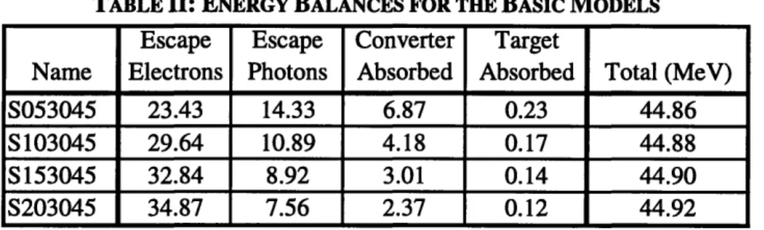
TABLE II: ENERGY BALANCES FOR THE BASIC MODELS
Escape Escape Converter Target
Name Electrons Photons Absorbed Absorbed Total (MeV)
S053045 23.43 14.33 6.87 0.23 44.86
S103045 29.64 10.89 4.18 0.17 44.88
S153045 32.84 8.92 3.01 0.14 44.90
S203045 34.87 7.56 2.37 0.12 44.92
The total values show that all the energy going into the model is being accounted for, either through escape or absorption, within an acceptable statistical variance. From this it
can be inferred that the model is running correctly and no unforeseen reactions are
occurring within the model. These results also show that the shorter c6nverters are
substantially better at producing photons.
There are several key factors that need to be considered when analyzing the
results of the radiantly cooled converter models. The Yield of the model shows the
models efficiency at converting electrons to on target GDR photons at a given beam
current. The heat deposition is the number of MeV absorbed by the converter out of the
incident beam energy, in this case 45 MeV. The heat deposition is one of two factors that
can limit the allowable beam current for the model. The maximum allowable heating for
each converter length is determined using the method outlined in section 2.3.2. The
maximum allowable heating is then divided by the heat deposition, giving the maximum
allowable current for the electron beam (max beam1, below). The second factor limiting
energy is taken from Figure 2. The smaller of these two values (max beaml and max
beam2, below) is therefore the maximum allowable beam current. The yield for each
model is then multiplied by the ratio of the maximum allowable beam current over the
beam current for the slug model (250gA) to give the current weighted yield. These results
are summarized in Table III below.
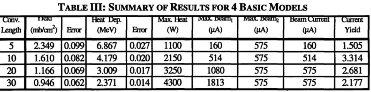
TABLE III: SUMMARY OF RESULTS FOR 4 BASIC MODELS
ength (/an 2 ) Error (M) E Emror (W) (pA) (pA) (pA) Yield
5 2.349 0.099 6.867 0.027 1100 160 575 160 1.505
10 1.610 0.082 4.179 0.020 2150 514 575 514 3.314 20 1.166 0.069 3.009 0.017 3250 1080 575 575 2.681 30 0.946 0.062 2.371 0.014 4300 1813 575 575 2.177
The 10-centimeter long converter plate shows the best performance out of the
four. This is due to the fact that it strikes a balance between yield and beam current. The
5-centimeter model has a higher yield, but it also has a higher heat deposition. This
combined with a lower allowable heating mean that the 5-centimeter model must be
operated at a lower current. The longer converters, 20 and 30-centimeters suffer from the
opposite problem. They are able to dissipate more heat then the accelerator is capable of
generating, therefore yield cannot be increased by increasing the current. By adjusting the
energy of the electron beam and the thickness of the converter it is possible to manipulate
these results. However, these changes have a much larger effect on the heating of the
converter than on the yield in the molybdenum target. Therefore, -only the 5 and
10-centimeter length converters were chosen for further study.
4.1.2 VARIATION OF PLATE THICKNESS
The first parameter chosen for optimization was the converter plate equivalent
through the plate when it is positioned at the designated angle. This "thickness" is therefore the length of tungsten the electron beam must pass through when it strikes the converter plate. The results will show that, to a point, as the equivalent thickness of the
slab decreases the yield in the molybdenum slug increases.
However, care must be taken in reducing the thickness of the converter. The
converter is going to operating at temperatures approaching 3000K. Even though
tungsten's melting point is over 3600K, this temperature is high enough such that the
issues of heat warping become a significant concern. If the converter is too thin its
strength will be decreased and as its temperature rises it can begin to warp. When
changes in equivalent thickness of 0.01-centimeter can have a substantial effect on
system performance, the warping of the converter plate must obviously be kept to a
minimum. For this reason a minimum plate thickness of 0.01-centimeter was chosen for
the converter plates designs. Verification of plate integrity at full power should be one of
the first items addressed in an experimental setup based on this design.
The effect of varying the equivalent thickness of the converter plate was studied
over a range of possible values. The minimum equivalent thickness' for the 5 and
10-centimenter designs, 0.05-centimeter and 0.10-centimeter respectively, were determined
by the 0.01-centimter minimum thickness requirements outlined above. The maximum
thickness for each was chosen by taking 40% the range of 45 MeV electrons in tungsten:
Energy (MeV) 45
0.40. Range(cm) = 0.40. Energy (MeV) 0.40 45 - 0.467(cm) = 0.50(cm)
2. -Density { gg 2 2.19.3
Scm2
The range between the maximum and minimum plate thickness was then divided by the
model. All of the calculations were performed with the electron beam energy set to 45
MeV. The results for these models are shown below in Table IV for the 5-centimeter
model and in Table V for the 10-centimeter model.
TABLE IV: RESULTS FOR VARYING THICKNESS ON 5-CM CONVERTER PLATE
Conv. Yield Heat Dep. Max. Heat Max. Beam1 Max. Beam2 Beam Current Current
Thickness (mb/cm2) Error (MeV) Error (W) (pA) (AA) p(A) Yield 0.05 1.941 0.089 1.349 0.009 1100 575 816 575 4.463 0.10 2.468 0.102 2.679 0.014 1100 575 411 411 4.054 0.15 2.480 0.102 3.842 0.018 1100 575 286 286 2.840 0.20 2.385 0.098 4.944 0.021 1100 575 222 222 2.122 0.25 2.321 0.098 5.951 0.024 1100 575 185 185 1.716 0.30 2.349 0.099 6.867 0.027 1100 575 160 160 1.505 0.35 2.270 0.097 7.783 0.030 1100 575 141 141 1.283 0.40 2.147 0.094 8.606 0.033 1100 575 128 128 1.097 0.45 2.013 0.090 9.433 0.035 1100 575 117 117 0.939 0.50 1.892 0.088 10.209 0.038 1100 575 108 108 0.815
TABLE V: RESULTS FOR VARYING THICKNESS ON 10-CM CONVERTER PLATE
Cony. Yield Heat Dep. Max. Heat Max. Beam1 Max. Beam2 Beam Current Current
Thickness (mb/crn2) Error (MeV) Error (W) (pA) (pA) (pA) Yield 0.10 1.757 0.086 1.972 0.012 2150 575 1090 575 4.040 0.15 1.850 0.088 2.606 0.014 2150 575 825 575 4.256 0.20 1.829 0.087 3.176 0.016 2150 575 677 575 4.207 0.25 1.744 0.085 3.696 0.018 2150 575 582 575 4.010 0.30 1.610 0.082 4.179 0.020 2150 575 514 514 3.314 0.35 1.636 0.083 4.633 0.022 2150 575 464 464 3.037 0.40 1.548 0.080 5.078 0.023 2150 575 423 423 2.621 0.45 1.543 0.081 5.487 0.025 2150 575 392 392 2.418 0.50 1.405 0.077 5.907 0.027 2150 575 364 364 2.046
These results show that varying the equivalent thickness of the converter plate can
have a substantial effect on the on the amount of energy absorbed. The decreasing
absorbed energy allows the beam current to be increased, which raises the current
weighted yield in the molybdenum slug. The models showed the 0.05-cm thick 5-cm
converter plate to have the best results with a current weighted yield of 4.463-mb/cm2;
the 0.15-cm thick 10-cm converter plate was close behind with a current weighted yield
4.1.3 VARIATION OF ELECTRON BEAM ENERGY
The second parameter chosen for optimization was the energy of the accelerated
electron beam. As outlined in section 1.2, the LINAC produced electron beam used in
this study is capable of operation over a variety of electron energies and beam currents.
The relationship between electron energy and maximum beam current is a linear one,
with current decreasing as electron energy increases. The results will show that as the
electron beam energy goes up, so does the yield in the molybdenum slug.
However, since the heat transfer properties of the system are so closely related to
the nuclear properties there is a far more complex relationship between electron beam
energy and optimum current weighted yield in the molybdenum target. As the electron
beam energy goes up the yield in the molybdenum target goes up, but the amount of heat
deposited in the converter goes up as well. For each length of the converter, there is a
limited amount of heat the converter is able to radiate. Therefore, at lower electron
energies, where the allowable current can be very large, the beam current is typically
limited by the heat deposition in the converter. At higher electron energies, where the
allowable current is relatively small, the beam current is typically limited by the
specifications of the LINAC. Sensitivity studies have shown that a balance is struck
between the heat transfer capabilities of the converter and the increased yield of the high
energy electrons when the maximum allowable beam current determined by the heat
transfer parameters is approximately 1.2 times the maximum allowable beam current
determined by the LINAC parameters. This relationship is only noticeable in converter
plates with relatively thin equivalent thickness. The relation exists for the thicker plates
as well, but the energy at which the maximum occurs is higher than the LINAC used here
increases the maximum possible current weighted yield in the molybdenum target decreases.
The effect of electron beam energy was studied over the entire range of operation for the LINAC, at 5 MeV intervals from 30 MeV to 60 MeV. All models were designed with a converter plate equivalent thickness of 0.30-cm. The results for these models are shown below in Table VI for the 5-cm converter plate model and in Table VII for the 10-cm converter plate model.
TABLE VI: RESULTS FOR VARYING ENERGY ON 5-CM CONVERTER PLATE
Electron Energy Yield Heat Dep. Max. Heat Max. Beam Max. Beam2 Beam Curent Current
(MeV) (mblm2) Error Er (M) Error (W) (piA) (ipA) (pA) Yield
30.00 1.078 0.066 5.293 0.021 1100 950 208 208 0.896 35.00 1.369 0.075 5.857 0.023 1100 825 188 188 1.028 40.00 1.965 0.089 6.400 0.026 1100 700 172 172 1.351 45.00 2.349 0.099 6.867 0.027 1100 575 160 160 1.505 50.00 2.648 0.105 7.315 0.029 1100 450 150 150 1.593 55.00 3.381 0.121 7.687 0.031 1100 325 143 143 1.935 60.00 3.700 0.125 7.987 0.033 1100 200 138 138 2.038
TABLE VII: RESULTS FOR VARYING ENERGY ON 10-CM CONVERTER PLATE
Electron Energy Yield Heat Dep. Max. Heat Max. Beam, Max. Beam2 Beam Current Current
(MeV) (mblcm2) Error (MeV) Error (W) (pA) (pA) (pA) Yield
30.00 0.800 0.058 3.065 0.015 2150 950 702 702 2.245 35.00 0.965 0.063 3.467 0.017 2150 825 620 620 2.394 40.00 1.345 0.073 3.869 0.019 2150 700 556 556 2.991 45.00 1.610 0.082 4.179 0.020 2150 575 514 514 3.314 50.00 1.941 0.090 4.515 0.021 2150 450 476 450 3.495 55.00 2.384 0.102 4.831 0.023 2150 325 445 325 3.099 60.00 2.634 0.107 5.125 0.024 2150 200 420 200 2.107
These results show that the variation of electron beam energy has a more subdued effect on current weighted yield than does the variation of converter plate equivalent thickness. This is not to say that the effect is unimportant, at a given thickness the variation of electron energy can change the current weighted yield by as much as 227%,
as is the case of the 5-cm converter plate. This effect decreases with increased converter
length, the 10-cm converter plate shows a variance of only 166%.
The variation of electron beam energy was next applied to the optimum converter
plate equivalent thickness models from section 4.1.2 to ensure that the final design was at
not only its optimum thickness but its optimum electron beam energy as well. Both the
5-cm and 10-5-cm converter plate models were analyzed with electron beam energies of
30-50 MeV. The results for these models are shown below in Table VIII for the 5-cm
converter plate model and in Table IX for the 10-cm converter plate model.
TABLE VIII: RESULTS FOR VARYING ENERGY ON OPTIMIZED 5-CM PLATE
Electron Energy Yield Heat Dep. Max. Heat Max. Beam, Max. Beamn2 Beam Current
(MeV) (mb/cm2) Error (MeV) Error (W) (pA) (pA) (pA) Yield
30.00 1.050 0.063 1.291 0.006 1100 950 852 852 3.578 35.00 1.407 0.055 1.333 0.007 1100 825 825 825 4.643
40.00 1.755 0.049 1.335 0.007 1100 700 824 700 4.913 45.00 1.941 0.046 1.349 0.007 1100 575 816 575 4.463
50.00 2.189 0.044 1.352 0.007 1100 450 814 450 3.939
TABLE IX: RESULTS FOR VARYING ENERGY ON OPTIMIZED 10-CM PLATE
Electron Energy Yield Heat Dep. Max. Heat Max. Beam, Max. Beam2 Beam Current Current
(MeV) (mb/cm2) Error (MeV) Error (W) (pA) (pA) (pA) Yield
30.00 0.897 0.061 2.003 0.011 2150 950 1074 950 3.408 35.00 1.033 0.064 2.229 0.012 2150 825 965 .825 3.408 40.00 1.523 0.078 2.455 0.013 2150 700 876 700 4.264 45.00 1.850 0.088 2.606 0.014 2150 575 825 575 4.256 50.00 2.071 0.094 2.804 0.015 2150 450 767 450 3.728
These results show that the 5-cm converter plate outperforms the 10-cm converter
plate by approximately 15% at optimized electron beam energy and converter plate
equivalent thickness. These models also support the observation that maximum current
weighted yield occurring when the ratio of max beaml to max beam2 is 1.2 in value. The
optimum single plate design will therefore be based upon the 5-cm converter plate model, with equivalent thickness of 0.05 cm and electron beam energy of 40 MeV.
4.1.4 OPTIMUM SINGLE INCLINED PLANE CONVERTER DESIGN
The optimum single inclined plane converter design was determined to be a 5-cm
converter plate model with an equivalent thickness of 0.05-cm and electron beam energy
of 40 MeV. This results in a yield of 1.755+0.049 mb/cm2 in the molybdenum slug. A
graph of the yield contribution over the GDR energy range is shown below in Figure 9.
FIGURE 9: YIELD FOR THE OPTIMUM INCLINED PLANE MODEL
For this case the maximum beam current is determined by the specifications of
the LINAC electron accelerator, see Table VIII. To produce 40 MeV electrons the
accelerator can be set to a maximum current of 700 gA. Therefore a current weighted
yield of 4.914±0.137 mb/cm2 is produced in the molybdenum slug. This also results in
the deposition of approximately 935 watts of power into the tungsten converter.
According to the simple radiant heat transfer model this would result in a surface
spreadsheet model, determined the peak temperature to be 2873K. This reduced
temperature is due to the conduction of heat to areas of the rectangular slab not directly
exposed to the electron beam. A graph of the temperature profile for one quadrant of the
slab is shown below in Figure 10.
FIGURE 10: TEMPERATURE PROFILE FOR OPTIMUM SINGLE PLATE CONVERTER
4.2 MULTIPLE INCLINED PLANES OF TUNGSTEN
The multiple plane model was originally conceived for the purpose of increasing
the surface area of the converter for radiant heat transfer. By increasing the heat transfer
of the system the beam current could be raised and the current weighted yield would
increase. In retrospect, with the limiting factor of the beam current for the single plane