Publisher’s version / Version de l'éditeur:
Canadian Geotechnical Journal, 7, 4, pp. 405-413, 1970-11
READ THESE TERMS AND CONDITIONS CAREFULLY BEFORE USING THIS WEBSITE. https://nrc-publications.canada.ca/eng/copyright
Vous avez des questions? Nous pouvons vous aider. Pour communiquer directement avec un auteur, consultez la
première page de la revue dans laquelle son article a été publié afin de trouver ses coordonnées. Si vous n’arrivez pas à les repérer, communiquez avec nous à [email protected].
Questions? Contact the NRC Publications Archive team at
[email protected]. If you wish to email the authors directly, please see the first page of the publication for their contact information.
NRC Publications Archive
Archives des publications du CNRC
This publication could be one of several versions: author’s original, accepted manuscript or the publisher’s version. / La version de cette publication peut être l’une des suivantes : la version prépublication de l’auteur, la version acceptée du manuscrit ou la version de l’éditeur.
Access and use of this website and the material on it are subject to the Terms and Conditions set forth at
Process of failure in ice
Gold, L. W.
https://publications-cnrc.canada.ca/fra/droits
L’accès à ce site Web et l’utilisation de son contenu sont assujettis aux conditions présentées dans le site LISEZ CES CONDITIONS ATTENTIVEMENT AVANT D’UTILISER CE SITE WEB.
NRC Publications Record / Notice d'Archives des publications de CNRC:
https://nrc-publications.canada.ca/eng/view/object/?id=f1bd65ca-ac61-4530-99b2-45549a505852 https://publications-cnrc.canada.ca/fra/voir/objet/?id=f1bd65ca-ac61-4530-99b2-45549a505852
Process of failure
in
icels2
Geotechnical Section, Division of Building Research, National Research Council of Canada, Ottarva, Canada
Received March 31, 1970
Information is presented on the failure behavior of columnar-grained ice during compressive creep and constant strain rate tests. The role of crack formation in establishing the failure condition is briefly described. Breakdown of structure is responsible for a marked change in the creep behavior of ice in the stress range of 10 to 12 kg/cm2. A ductile-to-brittle transition is observed at a strain rate of about 5 x 1 0 - b i n i n - ' . The upper yield stress in constant strain rate tests is shown to increase with increase in rate of strain up to the ductile-to-brittle transition. On presente des donnees sur le mecanisme de rupture de la glace B structure columnaire au
cours d'essais de compression B charge constante (fluage) et B vitesse de deformation constante.
L'importance de la formation des fissures pour 6tablir les conditions de rupture est brikvement dtcrite. La fissuration de la structure est responsable des changements dans la progression du fluage de la glace pour des contraintes variant entre 10 et 12 kg/cm2. Une transition de l'6tat ductile B 1'6tat fragile a ete observee B un taux deformation d'environ 5 X min-'. La limite apparente d'6lasticit6 durant les essais B taux constant de deformation unitaire parait
augmenter avec une majoration du taux de deformation jusqu'au point de transition de 1'Btat ductile B 1'6tat fragile.
Ice covers are of interest as a source of load on structures and as a surface for supporting loads. Because of the nature of ice pressure and bearing capacity problems, engineers re- quire knowledge concerning the strength of ice under various conditions of loading and the behavior of ice covers at failure. This informa- tion is needed for ice pressure calculations in order to determine the upper bound to the force that ice can exert. It is necessary for bearing capacity calculations to establish a reasonable factor of safety when loads are placed on ice covers.
Several factors make it particularly difficult to calculate the stresses associated with failure of ice covers. Ice is usually at a temperature close to its melting point and thus is in a "high
temperature" state. Its deformation and strength, consequently, are very dependent on temperature, rate of loading, characteristics of the cover, and how the load is applied. The rates of loading encountered in practice cover the full range of ductile and brittle behavior. This implies that the viscous or plastic behavior of ice must be taken into consideration for some problems, whereas elastic theory is ade- quate for others. It is still not possible, how-
'NRCC 11538.
-This paper is published with the permission of the Director of the Division.
ever, to establish from a design point of view for most situations the most critical mode of failure for given site and load conditions and the maximum stress that the cover will sustain. The problem is further complicated by the fact that deformation and failure depend on the type of ice, and the engineer usually has no control over the formation of the ice but must accept what is provided by nature.
It is the purpose of this paper to present information on the strength of ice during creep and during conditions of approximately con- stant rate of strain. The constant rate of strain observations extend into the region of the ductile-to-brittle transition. Information is also presented on the role that crack formation plays in the deformation and failure of ice and the dependence of this activity on stress, time, and strain.
Types of Ice
The various types of ice found in nature have been described and classified by Michel and Ramseier (1969). Two are of particular interest to engineers: columnar-grained ice, associated with the unidirectional freezing of lakes and rivers; and granular ice, associated usually with the flooding and subsequent freez- ing of snow or frazil slush.
Individual grains of ice tend to deform like
CANADIAN GEOTECHNICAL JOURNAL. VOL. 7, 1970
T l h l E h I l N
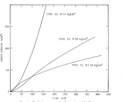
FIG. 1. Typical creep curves; T = -9 & 0.5 "C.
a pack of cards. The plane upon which slip occurs most readily is called the basal plane. The direction perpendicular to this plane is an axis of crystallographic symmetry, often re- ferred to as the "C" axis.
There are two types of columnar-grained ice commonly found in ice covers. If the conditions associated with the initial freezing of water are calm, each grain of the ice cover will tend to form with its direction of crystallographic sym- metry, or C-axis, parallel to the direction of growth. This orientation is retained as freezing proceeds, so that the planes of easy slip of each grain tend to be perpendicular to the direction of growth and to the grain boundaries.
If the conditions associated with the initiation of freezing are turbulent or if freezing is initiated by snowfall, the first grains to form will have random crystallographic orientation. Those grains with their C-axis tending to be perpendicular to the direction of freezing grow more readily; grains unfavorably oriented are suppressed and a preference soon develops for the symmetry axis of each surviving grain to be perpendicular to the direction of growth. In this case, the plane of easy slip of each grain tends to be parallel to the direction of freezing.
The two types of columnar-grained ice have been designated S1 and S2, respectively, by Michel and Ramseier. Granular ice, which usually has random crystallographic orientation has been designated T I .
The average grain size in the plane perpen- dicular to the long direction of the columnar- grains is usually larger for S1 than for S2 ice. In general, the grain size for both types in- creases in the direction of growth.
Creep of Ice
Characteristics of the creep behavior of types T1 and S2 ice are shown in Fig. 1. Type T I , granular ice, exhibits a behavior typical of ductile materials. There is an initial primary creep during which the creep rate continuously decreases, a secondary stage in which the creep rate is essentially constant, followed by a ter- tiary or accelerating creep stage that develops in the strain range of 1 to 2 % . Tertiary creep is often associated with the failure condition or terminated by it.
Type S2 ice exhibits a slightly different be- havior. If it has never been deformed before, it has an initial work softening or increasing creep rate stage. The creep'rate attains a maxi-
GOLD: PROCESS O F FAILURE IN ICE
TIME. M I N
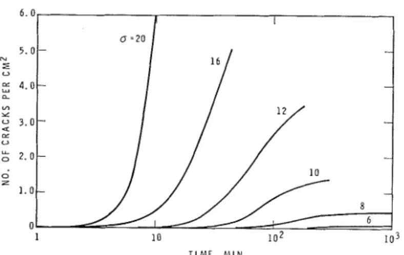
FIG. 2. Time dependence of crack density for compressive stress a kg/cm2, T = -9.5
+
0.5 "C.
mum value and a work hardening condition follows. This stage of decreasing creep rate is followed by the normal secondary stage, the tertiary stage and, if the stress is sufficiently large, failure. If previously undeformed Type S2 ice is strained into the secondary stage, the load removed and the specimen annealed, it exhibits type T1 behavior on reloading. Study of the deformed specimen shows that straining tends to break up the columnar-grained struc- ture and transform it into a granular one. The creep behavior of ice has been discussed by several individuals; see for example, Glen 1955, and Krausz 1968.
Considerable attention has been given to the dependence of the secondary creep rate on stress and temperature (Glen 1955; Steinemann 1954). In general, it is found that this depen- dence can be described (approximately) by an equation of the form
where
E = secondary creep rate
u = applied stress
T = temperature in degrees absolute
The loads of interest for most engineering problems occur during the primary stage of creep rather than the secondary. Little atten- tion has been given to establishing the stress and temperature dependence of the creep be- havior of ice in this important range of strain. Some information has been obtained for type S2 ice (Krausz 1963; Gold 1965).
An interesting feature of the behavior of type S2 ice is the rapid change in the character of the creep curve for a
-
12 kg/cm2 (170 p.s.i.).For an applied uniaxial compressive stress greater than this value the primary stage of creep passes directly to the tertiary, with no significant intervening secondary creep, as shown in Fig. 1 (Gold 1970). A similar obser-
vation was made by Brown (1926) in his
studies of the strength of ice from the St. Lawrence River. Laboratory studies showed that the onset of the failure condition (tertiary creep) within the first strain for stress greater than 12 kg/cm2 was due to the break- down of the structure by crack formation. Be- cause of the role it plays in establishing the failure condition in both laboratory tests and the field, a brief description of this cracking activity is given in the following section.
A and B are constants. Failure in Creep
The value for n is found to increase with When a constant compressive load is applied stress for type T I ice from about 2 at u = perpendicular to the long direction of columnar
4 kg/cm2 (56 p.s.i.) to about 4 for u = 12 grains of type S2 ice, a stress situation typical
kg/cm2 (170 p.s.i.). A similar dependence on for field conditions, crack formation occurs if
CANADIAN GEOTECHNICAL JOURNAL. VOL. 7, 1970
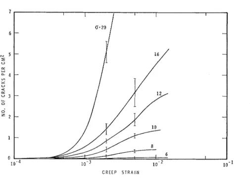
C R E E P S T R A I N
FIG. 3. Strain dependence of crack density for compressive stress u kg/cm2, T -9.5 &
0.5 "C. Height of vertical bars is twice the standard deviation in the observations.
(Gold 1966). This appears to be true also for a constant tensile stress, but the critical load may be a little lower. The cracks that form are long and narrow, with their long direction parallel to the long direction of the columnar grains and their plane parallel to the applied compressive stress. They usually involve only one or two grains. Their formation is a brittle event (i.e., they are cleavage cracks) and once formed do not appear to propagate to any significant degree with continued deformation.
The rate at which the cracks form depends upon stress, strain, and temperature. Figure 2 illustrates the dependence on time of the num- ber of cracks formed per cm2 of specimen surface area for various stresses at -10 OC. The cracks were observed visually in the 10 X
15 cm ( 4 x 6 in.) central area of specimens 25 cm long, 10 cm wide, and 5 cm thick (10 x 4
x
2 in.). Each curve is the average of six tests.Studies of cleavage crack initiation and prop- agation suggest that crack density is controlled primarily by strain rather than time. This is shown to be the case for ice in Fig. 3, where the observed crack density is plotted against strain for the same set of tests displayed in Fig. 2. It may be seen that the major cracking
activity takes place in the same range of strain for each stress. The maximum rate of cracking in previously undeformed type S2 ice occurs at a strain of 15 to 25 x A similar de- pendence of cracking activity on stress, strain, and time has been observed at temperatures of -5 OC, -15 OC, and -31 OC (23 OF, 5 O F ,
and -22 OF) (Gold 1970).
In general, it was found that if stress was smaller than about 10 kg/cm2 (140 p.s.i.), the rate of cracking tended to zero with continued deformation, as can be seen in Fig. 3. If the stress exceeded about 12 kg/cm2, the cracking rate decreased after the maximum, but was always appreciable. This behavior corresponded to the marked change in the characteristics of the strain dependence of the creep rate that occurred for the same range of stress, as shown in Fig. 1.
Observations of the spatial distribution of the cracks showed that during the initial de- formation they were uniformly distributed within each specimen. This appeared to be the case, as well, for the full range of deformation imposed for specimens subjected to a stress of 10 kg/cm2 or less. When the stress was 12 kg/cm2 or greater, crack formation tended to concentrate in zones parallel to the planes
GOLD: PROCESS O F FAILURE IN ICE
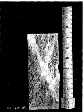
FIG. 4 . Crack distribution in Type S2 ice after creep of 0.32% under stress of 20 kg/cm2,
T = -10 "C.
of maximum shear after the maximum in the cracking rate. In many cases these zones be- come well defined "fault planes," as shown in Fig. 4. It may be more fully appreciated from this figure how this type of failure, which is not uncommon for materials tested in compression, is related to crack formation in this type of ice. The figure also demonstrates that brittle crack formation during compression is not inconsis- tent with an over-all ductile behavior, and can be responsible'for ductile type failure.
Ductile to Brittle Transition
It was found that the time to formation of the first large cracks during creep in com- pression had, in general, an exponential de- pendence on stress (Gold 1 9 6 7 ~ ) . This depen- dence was similar to that observed for the time to failure of various materials subjected to a constant tensile stress (Bartenev and Zuyev
1968). It would be expected that the formation of these large cracks in ice, under a tensile stress equal to the compressive stress, would probably result in failure. A transition from ductile to brittle behavior can be expected for ice in tension, therefore, if the stress exceeds about 8 kg/cm2 ( 1 15 P.s.~.).
It is clear from Fig. 1 that the ductile-to- brittle transition in compression does not occur at this stress or associated strain rate. The transition in behavior in the stress range of
10 to 12 kg/cm"s one involving the amount of strain to the tertiary stage, a strain that decreases in this stress range from a value in excess of 1 % to less than 0.25%. It can be appreciated that ice must strain relatively rapidly to maintain a uniaxial compressive stress greater than 12 kg/cm2 for appreciable periods. The behavior of ice is still ductile for a compressive stress of 20 kg/cm2. It is known
410 CANADIAN GEOTECHNICAL JOURNAL. VOL. 7 , 1 9 7 0
that at some significantly larger stress, or asso- ciated rate of strain, the behavior is truly brittle.
Failure for Constant Rate of Cross-head Movement
The foregoing discussion was concerned with the creep or constant load condition. For dy- namic load it is more meaningful to consider how the deformation behavior of ice depends on rate of strain. Very little information is avail- able for fresh-water ice. The behavior of type S2 ice for different rates of strain is depicted in Fig. 5 (Gold 1970; Gold and Krausz to be published). For small rates of strain, yielding occurs and the load subsequently drops to a relatively constant value. As the rate of strain is increased, the yield stress also increases, as shown by curves A and B. At a fairly well defined rate of strain, the behavior changes from ductile to brittle, as shown by curves C and D.
Observations were made on the behavior of laboratory-grown type S2 ice under conditions of constant rate of cross-head movement. The strain rate imposed on the specimens increased almost linearly to that corresponding to the
S T R A I N
FIG. 5. Stress-strain behavior for ice subject to a constant rate of strain. As the strain rate is in- creased the behavior is transformed from A through to D.
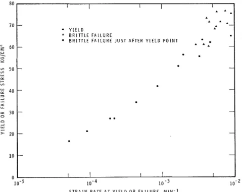
cross-head speed when yield or failure oc- curred. The dependence of the yield stress on the strain rate at yield for ductile behavior is shown in Fig. 6. It can be seen that the yield stress increased with the strain rate up to the ductile-to-brittle transition region, which began
at a rate of about 5 x min-l. Failure
lo-2 80 70 (Y I 6 0 - U
.
0 Y 50 'n u cx 6- VI $ 40 3 2-
Q: LL z 30 0 C1 2 W 20 10 0 S T R A I N R A T E A T Y I E L D OR F A I L U R E M I N - 1FIG. 6. Dependence of the yield point or brittle failure strength o n the strain rate at yield o r failure for type S2 ice.
I I 1 I I A * A - A * A Y l E L D A B R I T T L E F A I L U R E B R I T T L E F A I L U R E J U S T A F T E R Y I E L D P O I N T * A A -
.
-
- - - - - - --
- 1 I I I I 10-5GOLD: PROCESS OF FAILURE IN ICE
FIG. 7. Crack distribution after brittle failure of type S2 ice; strain at failure O.11%, T = -10 "C.
strength in this range of the brittle region was equal to about 70 kg/cm2 (1000 p.s.i.). Strain rate for the brittle cases was that at failure.
It was not possible to extend the observa- tions very far into the brittle region because of limitations imposed by the rate of cross-head travel of the testing machine. The specimens tested at rates larger than 5 X min-l had to be reduced in size to 3.8 x 7.6 x 19 cm (1.5 x 3 x 7.5 in.) in order to maintain the load at failure within the capacity of the machine. It may be seen in Fig. 6 that the change in specimen size does not appear to have had a significant effect on the yield and failure stress.
The study carried out by Gold and Krausz on natural ice of various types taken from the St. Lawrence River showed that type S1 columnar- grained ice is more brittle than type S2. It had a somewhat higher yield stress for given strain rate, particularly at the higher rates, and a
lower ductile-to-brittle transition region. Type T I granular ice had about the same dependence of yield stress on strain rate as type S2, but it was more ductile and its transition region was beyond the capabilities of the testing machine. Peyton (1968) has carried out studies of the strength of sea ice at large rates of loading. He found that the failure stress decreased sig- nificantly with increasing rate of loading when it was greater than about 2000 p.s.i./min. This corresponds to a strain rate of about 4 x 10-"in-l in the present work, and to the beginning of the ductile-to-brittle transition region. A similar drop-off in strength was not apparent for types S1 and S2 ice for rates of strain up to about twice this value. One of the reasons for the difference between the behavior observed by Peyton for sea ice and that ob- served for fresh water ice may be the porosity of sea ice owing to the presence of brine. It is probable that at high rates of loading (or
412 CANADIAN GEOTECHNICAL JOURNAL. VOL. 7, 1960
straining) the strength of sea ice is determined by the stress-raising characteristics of the brine pockets. It was observed in a study of the strength of fresh water ice taken from the harbor of Kingston, Ontario, that porosity had a very marked effect on the dependence of strength on rate of loading (Gold 1967b).
Crack formation was also a significant feature of the constant strain rate studies. The cracks appeared to form in a uniform manner through- out the specimen in the brittle range right up to failure. Brittle failure occurred by the abrupt formation of a fault zone. A n example is shown in Fig. 7. Similar cracking activity was observed in the ductile range, but here the decrease in stress after yield was associated with a barrelling type of failure, or with the development of zones approximately parallel to the planes of maximum shear in which crack formation tended to concentrate in a manner similar to that shown in Fig. 4.
Yield in the constant strain rate tests oc- curred over the same range of strain as the maximum rate of crack formation in the creep tests. It may be appreciated from Fig. 6 that the tests for strain rate greater than about 5 x 10-"in-' corresponded to the creep condition for stress larger than 1 2 kg/cm2. The yield point for this condition, therefore, is asso- ciated with structural breakdown due to the cracking activity responsible for the direct tran- sition of the primary to the tertiary stage in the creep tests. For constant strain rate tests in which the stress at yield is less than 10 kg/cm2, two yield points would be ex- pected: one associated with the structural changes that occur for strain between 0.1 and 0.25% ; and the second associated with the normal secondary and tertiary stages of creep, and which would develop at a strain of 1 to 2 % . Observations have shown that this is the case. For a nominal strain rate of 6 x 10-a min-l the second upper yield stress was larger than the first.
havior in the field indicate that the results of laboratory tests can probably be usefully ap- plied to engineering problems associated with ductile behavior. Attention must be given, however, to the fact that most laboratory studies have been carried out for uniaxial stress conditions, whereas most field situations involve biaxial or triaxial conditions. Nuttall and Gold
( 1968) have shown that the constraints asso- ciated with biaxial and triaxial stresses can have a marked effect on the ability of ice to sustain a load when its behavior is ductile.
In the brittle range of behavior failure is probably associated with points of stress con- centration such as might occur in the region of application of the load, or at internal or surface flows. Cracks propagate easily in ice. If the rate of straining is rapid, the tensile or shear stress necessary to maintain propagation is relatively small once the crack has been initiated. This characteristic of ice could explain the observed decrease in its strength with in- creasing rate of strain in the brittle region; and the low impact strengths that are often observed under field conditions. Field observations cer- tainly suggest that the impact force of even good quality ice is considerably less than would be predicted from laboratory-measured brittle strengths of 70 kg/cm2. Peyton's (1968) ob- servations of sea ice on Cook Inlet, Alaska, indicate that the most serious design condition may occur in the ductile region, just below the ductile-to-brittle transition.
As the strength of ice covers in the brittle region of behavior is greatly affected by quality, considerable attention will have to be given to the probability aspects of failure before the results of laboratory tests can be meaningfully applied to dynamic ice pressure problems. Further attention will have to be given, as well, to clarifying the modes of failure that occur in both the ductile and brittle range of behavior.
BARTENEV, G. M. and ZUYEV, Y. S. Strength and failure of viscoelastic materials. Pergarnon Press,
Concluding Remarks Oxford. 1968.
BROWN, E. 1926. Experiments on the strength of ice,
It is known that the results of deformation st. Lawrence Waterway Project, Report of Joint
and strength tests can be greatly affected by Board of Engineers. Appendix F. pp. 423-453. the condition of the test specimen and the GLEN, J. W. 1955. The creep of polycrystalline ice.
Proc. Roy. Soc. A. 228, pp. 519-538.
means which the load is to it'
GOLD, L. W. 1965. The initial creep of columnar-
Experience obtained from testing ice in the grained ice. Pt. 1 and 11. Can. J. Phys. 43, pp.
GOLD: PROCESS OF FAILURE IN ICE 41 3
1966. Dependence of crack formation o n crystallographic orientation for ice. Can. J. Phys. 44, p p 2757-2764 ( N R C C 9185).
1967a. Time t o formation of first cracks in ice. Int. Conf. Low Temp. Sci. Sapporo, Japan. Proc. 1, pp. 359-370 (NRCC 10226).
-
19676. Observations on the quality of the ice in Kingston Harbour, 20 March 1967. Na- tional Research Council of Canada, Division of Building Research, T N 488, 5 p.1970. The failure process in columnar grained ice. Ph.D. thesis, McGill University, Montreal, Quebec.
GOLD, L. W. and K u u s z , A. S. T o be published. An investigation of the mechanical properties of St. Lawrence River ice.
KRAUSZ, A. S. 1963. The creep of ice in bending. Can. J. Phys. 41, pp. 167-177 ( N R C C 71 1 7 ) .
1968. Plastic deformation of fresh-water ice. Conference on ice pressures against structures.
Quebec, P.Q., Assoc. Comm. Geotech. Res., T M 92, pp. 5-12.
MICHEL, B. and RAMSEIER, R. 0. 1969. Classification of river and lake ice based o n its genesis, struc- ture .and texture. Rept. 5-15, Department de Genie Civil, UniversitC de Laval, Qutbec, Qu6- bec.
NUITALL, J. and GOLD, L. W. 1968. Model study of ice pressures. I n Ice pressures against structures, National Research Council of Canada, Assoc. Comm. Geotech. Res., T M 92, pp. 125-130. PEYTON, H. R. 1968. Sea ice forces. I n Ice pressures
against structures. National Research Council of Canada, Assoc. Comm. Geotcch. Res., T M 92, pp. 117-123.
STEINEMANN, S. 1954. Flow and recrystallization of ice. Int. Union Geod. and Geophys., Int. Assoc. Sci. Hydrol., Rome, General Assembly, 4, pp. 4491162.