HAL Id: hal-02138473
https://hal.archives-ouvertes.fr/hal-02138473v2
Submitted on 28 May 2020
HAL is a multi-disciplinary open access
archive for the deposit and dissemination of
sci-entific research documents, whether they are
pub-lished or not. The documents may come from
teaching and research institutions in France or
abroad, or from public or private research centers.
L’archive ouverte pluridisciplinaire HAL, est
destinée au dépôt et à la diffusion de documents
scientifiques de niveau recherche, publiés ou non,
émanant des établissements d’enseignement et de
recherche français ou étrangers, des laboratoires
publics ou privés.
A behavior-based ontology for supporting automated
assessment of interactive systems
Thiago Rocha Silva, Jean-Luc Hak, Marco Winckler
To cite this version:
Thiago Rocha Silva, Jean-Luc Hak, Marco Winckler. A behavior-based ontology for supporting
au-tomated assessment of interactive systems. 2017 IEEE 11th International Conference on Semantic
Computing (ICSC), Jan 2017, San Diego, CA, United States. pp.250-257. �hal-02138473v2�
OATAO is an open access repository that collects the work of Toulouse
researchers and makes it freely available over the web where possible
Any correspondence concerning this service should be sent
to the repository administrator: [email protected]
This is an author’s version published in: http://oatao.univ-toulouse.fr/2
2 202
To cite this version:
Rocha Silva, Thiago
and Hak, Jean-Luc
and Alba Winckler, Marco Antonio
A behavior-based ontology for supporting automated assessment of interactive
systems. (2017) In: 2017 IEEE 11th International Conference on Semantic
Computing (ICSC), 30 January 2017 - 1 February 2017 (San Diego, CA, United
States).
Official URL:
https://doi.org/10.1109/ICSC.2017.73
A Behavior-Based Ontology for Supporting
Automated Assessment of Interactive Systems
Thiago Rocha SilvaICS-IRIT, Université Paul Sabatier Toulouse, France
rocha@irit fr
Jean-Luc Hak
ICS-IRIT, Université Paul Sabatier Toulouse, France [email protected]
Marco Winckler ICS-IRIT, Université Paul Sabatier
Toulouse, France winckler@irit fr Abstract -Nowadays many software development frameworks
implement Behavior-Driven Development (BDD) as a mean of automating the test of interactive systems under constn1ction. Automated testing helps to simulate use1·'s action on the User Interface and therefore check if the system behaves properly and in accordance to Scenarios that desc1ibe functional requirements. However, most of tools supporting BDD requù·es that tests should be w1itten using low-level events and components that only exist when the system is already implemented. As a consequence of sucb low-level of abstraction, BDD tests can hardly be reused with dive1·se a11ifacts and with versions of the system. To address this problem, this pape1· proposes to raise the abstraction leve1 by the means of a behavior-based ontology that is aimed at support ing test automation. The paper presents an ontology and an on tology-based approach for automating the test of functional re quù-ements of interactive systems. With the help of a case study for the flight tickets e-commerce domain, we demonstrate how tests written using our ontology can be used to assess functional requirements using different a11ifacts, from low-fidelity to full fledged UI Prototypes.
Index Terms - Automated Requù-ements Assessment, Behavior-Driven Development, Ontological Modeling, Testing of Interactive Systems.
I. INTRODUCTION
Assessing interactive systems is an activity that requires a considerable amount of effo,ts from development teams be cause it implies to assess systems features with respect to the many possible user entries and system outputs that might occlll· when a user is interacting with the system. Moreover, the sys tem behavior should pass acceptance testing, which is aimed to detenuine if the user's point of view about a feature is in ac cordance with the requirements previously specified. Thus, the automation of tests for assessing the system behaviors becomes a complex task that requires the use of frameworks to simulate the user's actions when interacting with the system.
In recent years there is an increasing interests both from ac ademic and industrial communities in Behavior Driven Devel opment (BDD) [1][2][3] for suppo,ting acceptance testing. One of the strengths of BDD is to suppo,t the specification of re quirements in a comprehensive natural language fonuat speci fication, the so-called User Stories [4]. This fonuat allows specify executable requirements, which means we are able to test requirements specification directly, conducting to a "live" documentation and making casier to the clients to set their final acceptance tests. It guides the system development and brings
the opportunity to test Scenarios directly on the User Interface (UI) with the aid of exterual frameworks for different plat forms.
Dtu-ing the last seven years, we have been involved in the development of e-Goverument applications where we have observed certain patterns of low-level behaviors that are reclll· rent when writing BDD Scenarios for testing functional re quirements with the UI. Besides that, we could also observe that User Sto,-ies specified in natural language often contain semantic inconsistencies. For example, it is not rare to find Scena,-ios that specify an action such as a selection to be made in semantically inconsistent widgets such as a Text Field. These observations motivated us to investigate the use of a formai ontology for describing pre-defined behaviors that could be used to specify Scena,-ios.
In this paper, we introduce the ontological mode! for sup porting the desc11ption of Scena11os and how such Scenarios can help the automated assessment of interactive systems. The ontology was developed based on the BDD principles, describ ing user's behaviors when interacting with UI elements in a Scena110-based approach. Results of the ontology validation are presented by demonstration of its co1Tectness through a con sistency checking. In addition, we describe an explorato,y case study that has been conducted for the flight tickets e-commerce domain. In this study, we have used otu· ontology-based tools to support the assessment of evolutiona,y Prototypes and Final User Interfaces. In the following sections, we discuss the foun dations for this work, how we have built the ontologie.al mode! to suppo,t the automated assessment of interactive systems, followed by its validation. We condude with a discussion and future works.
Il. FOUNDATIONS A. Computational Ontologi.es and Related Works
Computational ontologies are a mean to fo,mally mode! the stmcture of a system, i.e., the relevant entities and relations that emerge from its observation, and which are useful for a plll· pose [5]. Computational ontologies come to play in this work as a means to fo,malize the vocabulary and the concepts used
in User Sto,-ies, Scena,-ios and user's behaviors dlllmg the de velopment process of interactive systems. Without a common agreement on the concepts and terms used it would be difficult to support the assessment of user requirements. Some ap proaches have ti-ied to define languages or at least a common
vocabulary for specifying Uis for interactive systems. Useful abstractions for describing interactive systems include the components that compose the presentation of a User Interface and the dialog parts that describe the system behavior.
The Camaleon Framework [ 6] treats the presentation and the dialog in three levels of abstractions: Abstract, Concrete and Final User Interfaces. The idea is that as abstract user inter face component (such as a Container) could be refined to a more concrete representation (such as a Window) that will
ultimately feature a final implementation in a target platform (e.g. MacOS or Windows). User Inte1face (UI) specifications include more or less details according to the level of abstrac tion. The UsiXML (USer Interface eXtensible Markup Lan guage) [7] implements the principles of the Cameleon frame work in a XML-compliant markup language featuring many dialects for treating Character User Interfaces (CUis), Graph ical User Interfaces (GUis), Audito1y User Interfaces, and Mul timodal User Interfaces. UsiXML is a declarative language that captures the essence of User Interface components. At a highest level of abstraction, UsiXML describes concepts of widgets, controls, containers, modalities and intera.ction techniques. The dialog component of UsiXML is a state machine and it de scribes concepts of states, conditions, transitions and actions. Using a dedicated notation called SWC (StateWebCha1ts) [9], some authors [8] have demonstrated that it is possible to de scribe the system behavior at different levels of abstraction using UsiXML [8].
A glossary of recm1·ent terms for presentation components has published by the W3C in the MBUI (Model-based User Interface domain) [10]. It was intended to capture a common, coherent terminology for specifications and to provide a con cise reference of domain te1ms for the interested audience. For the dialog component, SWC [9] and SXCML (State Chart XML: State Machine Notation for Control Abstraction) [11] offer a language based on the State Machine concepts.
B. User Stories
User Stories in Software Engineering was first proposed by Cohn [4]. The author suggests to fonnalize User Stories in tenns of a1tifacts for describing feattu·es and their acceptance criteria, with concrete examples about what should be tested to consider these features as "doue". For that, the stories are for matted to fulfill two main goals: (i) assure testability and non ambiguous descriptions and (ii) provide reuse of business sce narios. Figure 1 presents a template proposed by North [12] and Cohn [ 4].
Ti tle { one 1 ine describing the story} Narrative:
As a [role] I want (feature] So that [benefit]
Acceptance Criteria: (presented as Scenarios) Scenario 1: Ti tle
Gi ven ( context]
And ( some more context) ...
When (event]
Then ( outcome]
And (another outcome] ... Scenario 2: ..•
Figure 1 Template for specifying User Stories, Nordt [12) and Cohn [ 4)
According to this template, a User Sto1y is described with a Title, a Narrative and a set of Scenarios representing the Ac ceptance Criteria. The Title provides a general description of the story, making reference to a feattu·e that this story repre sents. The Narrative describes the referred featm·e in tenns of the role that will benefit from the feattu·e, the featt1re itself, and the benefit it will bring to the business. The Acceptance Crite ria are defined through a set of Scenarios, each one with a Title and three main clauses: "Given" to provide the context in which the Scenario will be actioned, "When." to describe events that will trigger the Scenario and "Then" to present outcomes that might be checked to verify the proper behavior of the sys tem. Each one of these clauses eau include an "And" statement to provide multiple contexts, events and/or outcomes. Each statement in this representation is called Step.
In Behavior-Driven Development (BDD) [1], the user's point of view about the system is capttu·ed by the User Stories, described according to the template shown in Figm·e 1. BDD approach assumes that clients and teams eau communicate using this semi-structt1red natt1ral language description, in a non-ambiguous way (because it is supported by test cases).
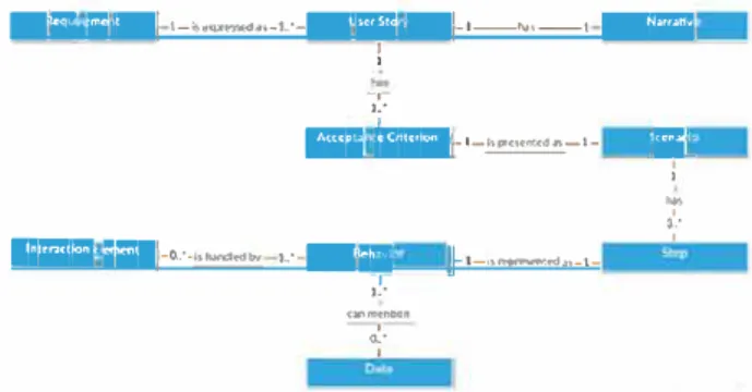
Following this assumption, we have defined a conceptual model to represent user requirements. Our focus is on fonction al requirements. A functional requirement defines statements of services that the system should provide, how the system should react to particular inputs, and how the system should behave in particular situations. To assure that the system behaves proper ly, requirements should be expressed in a testable way. Figure 2 presents the conceptt1al model that explains how testable requirements are formalized by our approach.
As show in Figure 1, a requirement is expressed as a set of User Stories (US) encompassing a Nat1'ative and a set of Ac ceptance Criteria. Acceptance Criteria are presented as Scenar ios at1d are composed by at least three main Steps ("Given.", "When" at1d "Then") that represent Behaviors which the system eau ai1swer. Behaviors handle actions on Interaction Elements in the User Interface (UI) and eau also mention examples of data that are sui table for testing them. The se concepts and mies ai·e defmed as classes ai1d axioms in the proposed ontology presented hereafter.
w·e,
n1,1n
1
-
l
-
!>
t��
i,s
-
,.
·
-
W'&k:M
�
·
·
-N
--
t
Wi®iii
1 1 -, L''
SW-12 fMIIMM
l
·
·
-
�
-
,
-IMW\t�i Mll
-
0-:-�-l-·W;ST·
�·-·��,,-l -L" (,ll'lffl('IIIIOn ' o.· 1Figure 2 Conceptual Mode! of User Requirements
li:\·
1 1'"'
3�:
Ill ONTOLOGY MODELING
The ontology we introduce in this paper bon-ows many concepts from languages and vocabularies in the literature. From Camaleon [6] and UsiXML [7] we get concepts of ab stract and concrete Uis. Presentation and definition of graphical components cornes from W3C MBUI [10]. The OWL specifi cation of the ontology (W3C Web Ontology Language) en compasses concepts (behavior and presentation aspects) of graphical components commonly used to build web and mobile applications and it aise contains textual representations that are used to describe how users internet with those graphical com ponents. Previous works with SWC [8] aise inspit·ed the con cepts used for desci·ibing the dialog.
The ontology has been modeled in Protégé 5.0. Figure 3 presents the root classes of the ontology. The classes Dialog,
Presentation and Platform mode! the concept of a Prototype. A Prototype is built for at least one Platfonn and is specified by
no more than one Dialog and one Presentation. A Dialog is
pe,fonued by a State Machine (detailed in section 3C) and a
Presentation is performed by the Interaction Elements (detailed
in section 3A). Likewise, the classes Narrative, Scenario, Step and Task mode! the concept of a User Story. A User Story is described by exactly one Narrative and some Scenarios. A
Scenario is an occtuTence of only one Task and is a set of Steps. A Step shall represent some Event, Condition and/or Action that are Transition elements from the State Machine,
pe1fon11.ing the Dia log component of a Prototype.
!!J
T· cmD!ll!l eoialoo .., ..• Interadion_Element eNarrative .., ..• Plotform • Presentation ... Prototype escenario .., ..• State_Machine_Element estep ..... Task • User_StorvFigure 3 Root classes of the ontology
The current version of the ontology bears an amount of 422 axioms (being 277 logical axioms), 56 classes, 33 object prop e,ties, 17 data properties and 3 individuals. A visual representa tion of ail the concepts can be found at https://goo.gl/IZgSJO and its complete specification in OWL can be found at
https://goo.ol/lpUMgp.
A. Modeling of Interaction Elements
Interaction Elements in the ontology represent an abstrac tion of GUI components in web and mobile platfonus. Figure 4 illustrates a hierarchy of Interaction Elements. The fotu· main superclasses are Container, Infonuation Component, Input Contre! and Navigational Component. The first one contains elements that group other elements in a User Inte1face, such as Windows and Field Sets. The second one contains elements in charge of displaying information to the use1-s such as Labels and Message Boxes. The third one represents elements in which users provide inputs to the system such as Buttons and
Text Fields. Finally, the last one contains elements usefül to navigate through the system such as Links and Menus. Sorne elements like Dialog Windows, for example, are inherited by more than one superclass, once they keep semantic characteris tics of Containe,-s and Information Components as well.
TOOI_Tip
8.IOWNr_Wln:low 1
•w-.,_Oiobg�
Figure 4 Cloud of User Interface Elements
B. Data Properties
Data Properties have been created to semantically describe data demains used by each Interaction Element. The root tree shown in Figure 5a gives an overview of the properties created, while Figtu·e 5b expands the Data Property "message", show ing that this kind of data is used by the Intera.ction Elements "Message Box", "Notification", "Tool Tip" and "Modal Win dow". "Message" has aise been defined to range the primitive data String. · lt·fü1$%i&i·ISi .,_. •actions ... ... aoreeme,11 ... adata_and_tîme_înput eimoaes ... alE!Vêl ._ aloc.ations .... •messooe ... •number_input .,_. aoptions ... •11aoes ... symbol atext_input ... mie •track_bar ... •value ... awords Show: P° th1sP' dlSJOtnt:l
Found 6 uses of message T ame.ss.,ge
amessaoe oomaln Messaoe_eox
a message oo,nahi Notification
a OdtaProperty-message •messaoe. Oomain Tool_Tip
•message Range: xsd:strîng amessage Domain t-lodal_Window Figure 5 (a) Left: Data Properties (b) Right: Data Property "message"
C. Modeling of the State Machine
The dialog part of a User Inte1face is described in the on tology using concepts borrowed from abstract State Machines as illustrated by Figure 6. A Scenario meant to be mn in a giv en UI is represented as a Transition. States are used to represent the original and resulting Uis after a transition occur. Scenarios in the Transition state always have at least one or more Condi tions (represented in Scenarios by the "Given" clause), one or more Events (represented in Scenarios by the "Wh.en" clause), and one or more Actions (represented in Scenarios by the "Th.en" clause). The clauses "Given", "Wh.en" and "Then" have been modeled as Individuals of each respective class.
η··• Nan-atJve - -li,--ePlotform l···• Prescntatlon
!
•
Prototype i···•sœnario! -E b4ffltMtMrtttlit#ttt#fü
· ·•Action . econdîtioo eevent ·•Stole erransltlon fndiv1d1nb by type�
�
\' eAàion (1) '···+Thon .. econdîtion (t) : .... GJven .., ... Event (1) · +when1 AonOUbon propcrty hlcr11rchy
OIIVI p1operty' hle,-afChy
Oiihtypcs
Figure 6 State Machine Elements and their Individuals
D. Object Properties
••••
Relationships between individuals in classes are represent ed as Object Properties. We have classified those properties in Relations and Behaviors. Relations group conceptual relation ships between objects from intemal classes, i.e. objects that do not directly address user's interaction. Behaviors group concep tual relationships between user' s interactions and Interaction Elements on the UI. These two groups are explained hereafter.
1) Relations:
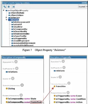
Figure 7 presents the set of main relationships between ob jects of intemal classes defined in the ontology. As an example,
Figure 8 presents the relations between elements in the State
Machine. As a sub property of Relations, objects from the Dia log class are composed by some States and Transitions. This relationship is described by the property isComposedBy (left side of Figure 8). Accordingly, objects from the Transition class are triggered by a sequence of some Conditions, Events and Actions. This relationship is described by the property isTriggeredBy (right-side of Figure 8).
Ob tct orooertv h1�rarc . rd�tons CIB 13:.:J
Y··• owl:topObji:«Property i -• aUowsMultiple \ .. ·aallowsUnique � • behaviors
•
aml!IJ!!lm
· •isAnOcam:mceOf ·•lsASetOf •isBuittfor · •lscomposodsv aisOe.scribe-dBy · • lsRepresentedBY•isSpecifiedBy
· •lsTrlaoerodev
· ashouldRepresent
ausesA.sAMobileElement
· •usesAsAWebElement
Figure 7 Object Property "Relations"
.. .
: SubP1optrty Of • relation.s lnvtrH Of Oom•1ns(,l'ltt11tebot1)0
eoialog SubP1optrtyOf a relationsli"
•
Transitionlht1tts(1Mt11uuon> V eïsTriggeredBv some Event
Ran.gH{•l'ltfl'\tC110fl)
eïsComposedBy some State eïsTriogeredBy some Condition
eïsComposed8y some1=r-ra_n_s,�1,on- �r,J' eisTriogeredBv some Action Figure 8 Object Properties isComposedBy (left) and isTriggeredBy (right)
2) Behaviors:
Following our ontological approach, the concept Behaviors is used to describe how users are supposed to interact with the systems whilst manipulating graphical elements of the User Inte1face. At first, behaviors can be described in a kind of stmctured natural language so that they can also be read by humans. As illustrated by Figure 9, the specification of behav
iors encompasses when the interaction can be perfo1med (using
Given, When and/or Th.en clauses) and which graphical ele
ments (i.e. Radio Button, CheckBox, Calendar, Link, etc.) are suitable to implement the expected system behavior. In the example below, the behavior receives two parameters: a "$ele
mentName" and a "$locatorParameters". The füst parameter is
associated to data, the second parameter refers to the Interac tion Element supported by this behavior: "Radio Button",
"CheckBox", "Calendar" and "Link''. To comply with semantic
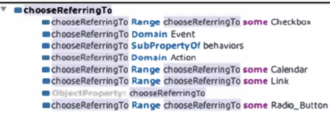
mies, the behavior "] chose \ "$elementName\" referring to \ "$locatorParameters\ "" shown in Figure 9 can be modelled into a predefined behavior "chooseReferringTo" as shown m Figure 10.
1 cnoose rse1sm9n1Nam9r re:srnng 10 \''!locatorParame1srsr
ca1sraar UOk
• •chooseReferrlngTo
• chooseReferringTo Range chooseReferringTo some Checkbox •chooseReferringTo Domain Event
•chooseReferringTo SubPropertyDf behaviors
• chooseReferringTo Domain �ion
•chooseReferringTo Range chooseReferringTo some calendar
•chooseReferringTo Range chooseReferringTo some Link
• chooseRefaningTo
•chooseReferringTo Range chooseReferringTo some Rad10_Button
Figure JO Behavior "chooseRefferingTo"
Our ontology includes a large set of predefined behaviors. Sorne of them are show at Table 1. Notice that each Behavior is associated to diverse transition components ( Context, Event and/or Action) that compose a Transition. The colulllll Interac tion Elements in Table 1 enlists the set of Interaction Elements that can fit to trigger a pa1ticular behavior.
TABLE l. SOME OF PREDEFINED BEHA VIORS ON THE ONTOLOGY
Beha�ior Transition Interaction Elements
C E À Calendar
choose Checkbox Radio_Button
Linlc
chooseBvlndexlnlheField Droodovvn List
Calendar
chooseReferringTo Checkbox Radio_Button
Linlc
chooseTheOotionO!Va /ueln TheField Droodovvn List
Menu
clickOn Menu_Item Button
Linlc Menu clickOnReferringTo Menu_Item Button
Linlc
doNotTypeAnyValueToTheField
-
Text_FieldresetTheValueom,eField
r,oTo Browser Window
isDisolaved Window
Dropdov,n _ List
setlnTheField = tryToSetlnTheField Text Field Autciëomplete
Calendar
1 nmeAndChooselnlheField Autocomnlete
wil/BeDiso/ayed Text
The vocabulary chosen to express each behavior has emerged from Scenarios specified in our past projects. It out lines only one of the several possible vocabularies to represent the same user's behaviors, and could be extended in the futtu·e by more representative phrases or expressions. Some synonyms conceming the user's goal have been also identified in order to increase the expressivity of the ontology. For example, the
behavior doNotTypeAnyVa1ueToTheField is considered equivalent
to the behavior resetTheValueOfTheField as they perform or
assert exactly the same action on the affected UI element, look
ing for the same output. Likewise, the behavior setinTheField
is equivalent to the behavior tryToSetinTheField as they intend
the same action, being the second one more suitable to express attempts of violation in the business mies for testing pttrposes.
IV. VALIDATION
The ontology has been validated in two steps: at first, con sistency has been continuously checked through the use of reasoners. Then, using a tool suppo1t, we applied the approach to a case stt1dy in the flight tickets e-commerce domain. We have developed tools for dealing with tests over Prototypes and for testing the implementation. A first tool named PANDA (Prototyping using Amiotation and Decision Analysis) [13) was built to design and test UI Prototypes. A second tool was de veloped to testing Web Final Uls derived from the Prototypes. Both tools have been used to conduct the case study.
A. Consistency Checking
For checking the consistency of the ontology we use the reasoners FaCT++, ELK, HermiT and Pellet. FaCT++ started identifying no support for the datatypes xsd: base64Binary and xsd:hexBinary used to range images and symbols in the Data Properties. Those properties have been used to define domains for objects in the classes Image Carousel and Icon, respective ly. ELK has failed by no support to Data Prope1ty Domains as well as Data and Object Prope1ty Ranges. HenniT and Pellet have succeeded processing the ontology respectively in 4926 and 64 milliseconds, as presented in Figure 11.
Z:lifC 13:c,�:09 ---- --- --·---· urro 13:00:09 Fr:-ecc;pJtl...'W :..r.!�:c.nc,u: Ufl"O ll:00:09 -cl.,.,., h.lererchy
O.TO 13:00:09 - Ol>)ec� Pl'QPel'W hltt'al'ChY
nrro 13:00:09 -d,te pro�:ty luea«.:bv tlfl"O ll:00:09 -cl.,.,., .,.,:,e:n:ion., n.-ro 13:00:09 - 01>1ec� properw aa,enloos
urro 13:00:09 - d�te pro�:ty un:t1or.,
!Jfl"O 13:00:09 - .,llltC lMl.VldUd.,
n.ro 13:00:14 C1l�1001ea proce88ed 10 492t m bV ouu
nrro u:00:1.t
Uff"O ll:0:01
n.ro 13:01:01 Pre-coi,wttno-1.nrere.nces: urro 13:01:01. -clo$:c h.u:uc.bv tlfl"O u:01:01 - o1>3ect proper<ty ht.el'.,uehy n.-ro 13:01:01 - data property hiera.rchy
Ilff'C- 13:01:01. - cle$:; 0$:c::-ti.O.I'..$
tlfl"O u:01:01 -obJect proper<ty .,.,,enle."1., n.ro 13:01:01 - data propert:r asser�lon,
Il<FO 13:01:01. - n::-� iMJ.vidu«h
!Jfl"O u:01:01 ontologie., r,l'.-Oce,.,ed ln 611 l'l.5 by Pellet: n.ro u:01:01
Figure 11 Resuhs of ontology processing: HermiT (top) and Pellet (bottom)
B. Validation by a Case Study
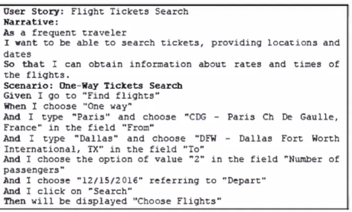
T o illustrate how the ontology can be used to support the specification of requirements and the testing automation for intera.ctive systems, we have chosen a flight tickets e commerce application. Figure 12 describes one of the User Stories from this case stt1dy with a Scenario for searching flights. Therein, the user should provide at least: the type of sought ticket (one-way or round trip), the departure and the all'ival airpo1ts, the number of passengers, and frnally the dates. In the Scenario "One-Way Tickets Search", a typical search of tickets is presented conceming a one-way trip from Paris to Dallas for 2 passengers on 12/15/2016. According to the busi ness rnle, the expected result for this search is a new screen presenting the title "Choose Flights", in which the user might
select the desired flight from a list of flights matching his search.
Oser Story: Flight Tickets Search Narrative:
As a frequent traveler
I want to be able to search tickets, providing locations and dates
So that I can obtain information about rates and times of the flights.
Scenario: One-Way Tickets Search
Given I go to "Find flights'* Wh.en I choose ··one way ..
And I type '"Paris'· and choose '"CDG - Paris Ch De Gaulle1 France'" in the field "From"
And I type '"Dallas" and choose "DFW - Dallas Fort Worth International1 IX" in the field "To'"
And I choose the option of value "'2" in the field "'Nu.rober of passengers"
And I choose "12/15/2016" referring to "Depart"
And I click on "'Se.arch"
Th.en will be displayed '*Choose Flights"
Figure 12 User Story for Flight ncket Search in 1he testing template format
1) Ontology Support for Testing Prototypes using PANDA:
PANDA [13] is a tool suppo,t for the creation and testing of UI Prototypes built upon an ontology. PANDA sta,ts by read ing an OWL file describing our ontology. Using the inner or ganization of ontologie.al classes, PANDA dynamically instan
tiates a palette of widgets (see Figure 13) that can be used to
build a Prototype. From an interaction point of view, the con struction of Prototypes is done by perfonning drag and drop operations. From a storage point of view, a Prototype is an XML file that describes a composition of widgets whose de scription is semantically annotated by elements of OUI' ontolo
gy. 0 X lut1on 5"tch. l'Toper111• >< Q.•
--
-S..d,-
--·
·
--
V--
--
��
,
...
....
·-
--
'9Nint.:ltilMl!lt�-
-
_
__ ..
..
...
---
...
..
Ttt<...
,
... _y-·
--
-
120.0--
-
-
--
,,..
o...wn.� �ftrm9To--
-
...
..---...
--
---
c:>tC'!'oll'llellll-
..,,,.
·-
--w--·-
-
.t.o.l!onflllea,--·
--
--
ButlCN'I S,ea,dt•
-��('--·
-
�ofSWd'I·
--
1:1Figure 13 Pallets wilh 1he widget Button and its properties extracted from the
ontology
For the construction of the palette, PANDA uses a descrip tion of a widget we called "Ontologica/Class" which feature its name, list of subclasses and set of properties. This ontological class has been defined as a generic class that is customized through its properties. Indeed, those classes represent each component of a Prototype in PANDA and its behaviors regard ing their usage in the prntotyping tool: they are placed in an
edition area in which the user can edit the instance of a proper ty. Thus, for the Presentation component, PANDA uses a flexi ble structure that allows to dynamically instantiate the set of
widgets that will be used to build Prototypes.
PANDA creates a category for each superclass including:
Container, Information Component, Input Control, Interaction Element, Navigational Component, Platfonn, State Machine Element, Window and Window Dialog. Each category contains a set of widgets defined by the classes inheriting the superclass. As for the prope,ties, ontological classes are displayed in the prope,ty window in the category "Ontological properties". Each property identified in the ontology is therefore inse1ted in the list of prope,ties of the class with a name and a value.
For the Dialog component, OUI' ontology encompasses be havioral prope1ties to describe the interaction suppo1ted by a class. For example, a Butten must feature a behavioral property
"clickOn" which indicates that buttons suppo,t an event click.
Click events allow the designer to specify interactions on widgets. If a button has a behavioral prope,ty "clickOn", PANDA adds an event handler to handle click events when users interact w'ith the Prototype.
Uscmarne
Ln1 name
Flnd n9111s Rcundll1p
F,om To
Ono> v,-;;iy Round l11p • Il�
One-Way Tickets Search
M Given I go to "Flnd nlghts"
M When I choose "One wa'{'
[X] And I type "Paris" choose "CDG · Paris Ch De Gaulle, France"ln the field "From"
[X] And I type "Dallas" choose "DFW -Dallas F o,t wo,th International, TX'ln tne neld "To"
[X] And I choose the option or value "2"in the field "Number or passengers" [X] And I choose "12/15/2016"rererring to "Deparf'
M And I click on "Search"
M Then wll be dlsplayed "Choose Fli hts"
Ftigllh Oepartur� Anwal Ch�c�
49 11:XI .m OO.l5vrn
BA0::05 COG OFW
liEEI 07:.CS 8l'YI œ·1oarn
Q)et":otcdby COG LHR BritîshAir,,,\'lys 51 œ:ss 3M 12:25 prn LHO OFW $1711 Re,fundab!e $1706
::J
Re.fundab!eFigure 14 A State Machine Transition between sketches of a PANDA Proto
type for 1he User Story "Flight Tickets Search" From top to bottom: the initial State "Find Flights", a Transition represented by the Scenario
"One-Way Tickets Search", and finally the resultant State "Choose Flights"
Figure 14 shows how Scenarios are tested in PANDA. For each Step of Scenarios, PANDA assess actions with respect to widget prnperties defined in the ontology. For example, in the Step "And I click on 'Search"', PANDA looks for any widget
named "Search" in the initial State, and check if the description of the widget in the ontology suppo1t the behavior "clickOn". The results of the tests are displayed by a colored symbol next to each Step, a red "X" representing failure, a green "V" repre senting success, and a black"?" representing an untested Step.
2) Ontology Support for Testing Web Final Uis:
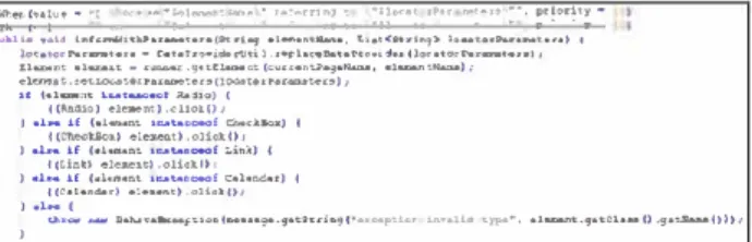
To test the Scenarios over Web Final Uls, we have em ployed a set of frameworks to provide automated simulation of user's interaction. More specifically, we have used Selenium WebDriver to mn navigational behavior as well as JBehave and Demoiselle Behave to parse Scenario scripts. The ontology is charged as a CommonSteps Java Class, pre-defining behaviors that can be used when writing Scenarios, and where each action and/or asse1t for each behavior is defined. This class imple ments the dialog component and contains al! the knowledge about how pe1forming the mentioned behaviors on the UI ele ments, thus when using them to write Scenarios, tests are deliv ered without any additional effo1t of implementation. Hence, methods in this class have been wTitten for every Step ad dressed on the ontology. As illustrated in Figtu·e 15, behaviors
"Whenffhen I choose ' ... ' referring to ' ... "' are addressed to the Selenium method clickO, with the appropriated sequence of actions to perform this task on the Final UI. As this behavior can be pe1fo11ned only in Radio Buttons, Check Boxes, Links or Calendars, the concrete instance of any of these elements are searched on the Presentation layer.
::eni'll�\111 • -� _,.�,.. . .,. ·-·��-��"""'".::r Y"�"-rl;� �� :!!�'""' ,,rP" ""':•y• :::·· :1'�01'�'-: •
!"'l>l�c-::!:�:::::-.:·::;::1:��:!1:::;;::.�::r�!:::::��!:,;:::--..::::;;.,,•> 1 �t-.n1; •l-.&'-• .,,.,_.,.,., .. u __ .._._(.,.,.-�.n�-9.-, •l-•-);
d�ni;, i,e1;t()(IO�Mt-11.;-u.eu·o(loootonot<llll.e�O),
U i•l_.,,_ 1 Cbcli?) .__,...,.cl' a.ei-.ni;) .ollolO,uo) , ( 1 •t- H (ICCM<llSO.:•1•...,nt ) el�nt,_,__n_! >,olhlO..c-:uioOJ ><J 1 ) .i.- i..f C(LitlU c.i. ... nt el-n).olhl,_...,n_! U1 t.inll) 1
) •'-- H cce•�•nc.i.,...,,n •><> •i-. .. �,_,__).,._! oHoic..ho, n.dou) 1
) •L:;:,.!.. ,._ tl•"-"••l:>o-f'U0Al-••...,.•'f•'-lll .. d,f>'9l••,.._.,.�i.:.,. tA�•tt.t C)�", •1-�.,•�tb.••0 •<J•�-1)))1 )
Figure 1 S Behavior "chooseRefferingTo" being structured as a Java method
The Presentation component includes the MyPages Java Class that makes the mapping between abstract UI elements of the ontology and the concrete/final UI components instantiated on the interface being tested. For that pwpose, we make use of annotations in Java code following the Page Objects pattem [14] as illustrated in Figtn·e 16. UI components are identified through their XPath references or some other unique ID even t:ually used for some frameworks to implement the inte1face. This link is essential to allow the framework to automatically mn the Steps on the right components on the Final UI.
public class llyPages {
@ScreenMap(name = "Find Fligbts", location = " •• ")
public class MainPage {
ElementM.ap{name = "Searcb"., locatorîype = Element
iLocatorîype.XPath, locator = " ... ") // concrete 01 component
rivate 1111.tbm Searcb· // abstract UI element
Figure 16 Concrete and Abstract UI elements being associated in a Java class For behaviors not addressed by the ontology, the MySteps Java Class allows developers and testers to set their own
busi-ness behaviors and implement as well how they should be at tended by the Selenium methods on the UI components. For both classes the main incomes are behaviors extracted from the User Stories that can be represented in simple packages of text files.
In short, once the ontology is charged, it is enough to iden tify on the Final UI under testing the concrete UI elements that were instantiated to represent abstract UI elements. Afterwards, when Scenarios are triggered, the application mus and Seleni um perfonus Step by Step the specified behaviors, repo1ting testing results either by the JUnit green/red bar or by JBehave reports with the context and attached print-screens of each identified failw·e.
C. Discussion
The ontology presented in this paper only describes behav iors that report Steps of Scenarios perfo1ming actions directly on the User Interface through Interaction Elements. Thus, the ontological mode! is domain-free, which means that it is not dependent of business characteristics that are described in the User Stories. Specific business behaviors shall be specified only for the systems they make reference, not affecting the whole ontology. Therefore, it is possible to reuse Steps in mul tiple testing Scenarios. For example, the ontological behaviors
goTo, choose, typeAndChooselnTheField, chooseTheOption OfValueinTheField, chooseReferringTo, clickOn and willBe Displayed presented in Figtire 12 can be easily al! reused for
any other Scenario of any other system requiring those kind of user's actions.
However, it brings the need to specify Scenarios in the user interaction level, writing Steps for each click, selection, typing, etc. A possible solution to avoid it would be to work with high er level behaviors that are described by user's tasks. Nonethe less, user's tasks often contain info1mation from specific appli cation domains. For example, high level Steps like "When I search for flights to 'Destination"' encapsulate al! low level
behaviors making reference for individual clicks, selections, etc.. however it also con tains information that refers to the airline domain (i.e. behavior "search for flights"). So that Step would only makes sense on that particular application domain. For fürther researches, it could be interesting to investigate domain ontologies to be used in parallel with 01ir ontology, defining a higher level business vocabulary database in which business behaviors could be mapped to a set of interaction behaviors, covering recun-ent Scenarios for a specific domain, and avoiding them to be wTitten every time a new interaction may be tested.
Another aspect to be discussed is that even having mapped synonyms for some specific behaviors, otu· approach does not provide any kind of semantic inte1pretation, i.e. the Steps might be specified exactly as they were defined on the ontology. The use of the JBehave plugin for Eclipse has helped us to know visually (through different colors) on real time if some Step that is being written exists or not on the ontology. This resotu·ce reduces the workload to remember as exactly some behavior has been described on the ontology.
At first glance nonetheless the restricted vocabulary seems to bring less flexibility to designers, testers and requirements
engineers, but on the other hand, it establishes a common vo-cabulary, avoiding typical problems of ambiguity and incom-pleteness in requirements and testing specifications. Naturally, investigating the use of Natural Language Processing (NLP) techniques could improve the specification process, adding more flexibility to write Scenarios that could be in some extent semantically interpreted to meet the behaviors described on the ontology. This issue is certainly a worthwhile topic for further researches.
It is also worthy of mention that the concepts and defini-tions in the ontology presented herein are only one of the pos-sible solutions for addressing and describing behaviors and their relations with UIs. Despite being based on well-known languages such as MBUI, UsiXML and SCXML besides being provided ready to use for a new development project, we con-sider that the ontology might evolve to include other behaviors, concepts and relationships that could be eventually more repre-sentative for some contexts of development. It could be made through the use of direct imports in the ontology or simply adding new more expressive behaviors to the Object Property “behaviors” and linking them to the appropriate set of Interac-tive Elements.
Finally, when representing the various Interaction Elements that can attend a given behavior, the ontology also allows tending multiple design solutions for the UI, representing ex-actly the same requirement in different perspectives. Thus even if a Dropdown List has been chosen to attend for example a behavior setInTheField in a Prototype, an Auto Complete field could be chosen to attend this behavior on the Final UI, once both UI elements share the same ontological property for this behavior under testing. This kind of flexibility makes tests pass, leaving the designer free for choosing the best solutions in a given time of the project, without modifying the behavior specified for the system.
V. CONCLUSION
In this paper we have presented a behavior-based ontology aiming at test automation that can help to validate functional requirements when building interactive systems. The proposed ontology acts as a base of common vocabulary articulated to map user’s behaviors to Interaction Elements in the UI which allows us to automate tests. The ontology also provides im-portant improvements in the way teams should write require-ments for testing purposes. Once described in the ontology, behaviors can be freely reused to write new Scenarios in natu-ral language, providing test automation with little effort from the development team. Moreover, it allows specifying tests in a generic way that can be reused along the development process. For that reason, we are also investigating the use of the ontolo-gy to test model-based artifacts such as low-fidelity Prototypes and Task Models. Tests in these artifacts could be conducted through a static verification of their source codes and would help to integrate testing in a wider spectrum of artifacts com-monly used to build interactive systems.
We have also presented tools that demonstrate how this on-tology can support testing of interactive systems. So far, only
interactive Prototypes built in PANDA can be tested by the ontology once it requires that tools are able to read and support the set of described behaviors. On the other hand, tests in Web Final UIs can run independently of the frameworks used to build these UIs. It is possible because tests provided by our tool assess the concrete UI elements found on the interface in the final HTML page.
A. Future Works
We envision a set of future works in this theme including experiments to evaluate the acceptance of the approach in a case study with users, especially when manipulating more complex behaviors in real cases of software development. It would be useful to collect data about the effectiveness and the workload when specifying tests using the ontology. Other case studies including mobile platforms are planned as well.
Future discussions might also consider having ontologies as knowledge bases, keeping specific behaviors for specific groups of business models in domain ontologies. It would al-low us to also reuse entire business Scenarios in systems shar-ing similar business models.
REFERENCES
[1] D Chelimsky, D Astels, B Helmkamp, D North, Z Dennis and A Hellesoy, “The RSpec Book: Behaviour Driven Development with Rspec, Cucumber, and Friends,” Pragmatic Bookshelf, 2010
[2] K Pugh, “Lean-Agile Acceptance Test-Driven-Development,” Pearson Education, 2010
[3] G Adzic, “Specification by Example: How Successful Teams Deliver the Right Software,” Manning Publications, 2011
[4] M Cohn, “User Stories Applied: For Agile Software Development,” Addison-Wesley Professional, 2004
[5] N Guarino, D Oberle and S Staab, “What is an Ontology?” in Handbook on ontologies, Springer Berlin Heidelberg, p 1-17, 2009 [6] G Calvary, J Coutaz, D Thevenin, Q Limbourg, L Bouillon, J
Vanderdonckt, “A Unifying Reference Framework for multi-target user interfaces”, in Interacting with Computers 15(3): 289-308, 2003 [7] Q Limbourg, J Vanderdonckt, B Michotte, L Bouillon and V
López-Jaquero, “USIXML: a Language Supporting Multi-Path Development of User Interfaces,” EHCI/DS-VIS, 2004
[8] M Winckler, J Vanderdonckt, A Stanciulescu & F Trindade, “Cascading dialog modeling with UsiXML”, in International Workshop on Design, Specification, and Verification of Interactive Systems, p 121-135, 2008, Springer Berlin Heidelberg
[9] M Winckler, P Palanque, “StateWebCharts: A Formal Description Technique Dedicated to Navigation Modelling of Web Applications”, in Design Specification and Verification of Interactive Systems (DSV-IS), p 61-67, 2003, Springer-Verlag
[10] J Pullmann, “MBUI - Glossary - W3C”, Fraunhofer FIT, 2016 [Online] https://www w3 org/TR/mbui-glossary/
[11] J Barnett et al , “State Chart XML (SCXML): State Machine Notation for Control Abstraction”, W3C, 2016 [Online] http://www w3 org/TR/scxml/
[12] D North, What's in a Story? 2016 [Online] http://dannorth net/whats-in-a-story/
[13] J-L Hak, M Winckler and D Navarre, “PANDA: prototyping using annotation and decision analysis,” in Proceedings of the 8th ACM SIGCHI Symposium on Engineering Interactive Computing Systems (EICS '16), ACM, New York, NY, USA, p 171-176, 2016
[14] M Fowler, PageObject, 2016 [Online] http://martinfowler com/bliki/PageObject html