HAL Id: hal-01590351
https://hal.archives-ouvertes.fr/hal-01590351
Submitted on 19 Sep 2017
HAL is a multi-disciplinary open access
archive for the deposit and dissemination of
sci-entific research documents, whether they are
pub-lished or not. The documents may come from
teaching and research institutions in France or
abroad, or from public or private research centers.
L’archive ouverte pluridisciplinaire HAL, est
destinée au dépôt et à la diffusion de documents
scientifiques de niveau recherche, publiés ou non,
émanant des établissements d’enseignement et de
recherche français ou étrangers, des laboratoires
publics ou privés.
Baptiste Angles, Marco Tarini, Brian Wyvill, Loic Barthe, Andrea
Tagliasacchi
To cite this version:
Baptiste Angles, Marco Tarini, Brian Wyvill, Loic Barthe, Andrea Tagliasacchi. Sketch-Based Implicit
Blending. ACM Transactions on Graphics, Association for Computing Machinery, 2017, Proc. of
Siggraph Asia 2017, 36 (6), �10.1145/3130800.3130825�. �hal-01590351�
BAPTISTE ANGLES,
University of Victoria, Université de Toulouse, and IRIT / CNRSMARCO TARINI,
Università dell’Insubria and ISTI / CNRBRIAN WYVILL,
University of VictoriaLOÏC BARTHE,
Université de Toulouse and IRIT / CNRSANDREA TAGLIASACCHI,
University of Victoriac o m p o s i t i o n f u n c t i o n s A B C D E A C E B D
Fig. 1. A user’s 2D sketches (bottom-left) are used to exemplify desired ways in which implicit functions should be composed together. From these, our algorithm automatically derives new custom gradient-based composition operators (bottom-right). These can then be applied to combine any 3D (or 2D) implicit model (top) replicating the user’s intentions, and including effects such as contacts, bulging deformation, or smooth blends.
Implicit models can be combined by using composition operators; functions that determine the resulting shape. Recently, gradient-based composition operators have been used to express a variety of behaviours including smooth transitions, sharp edges, contact surfaces, bulging, or any combinations. The problem for designers is that building new operators is a complex task that requires specialized technical knowledge. In this work, we introduce an automatic method for deriving a gradient-based implicit operator from 2D drawings that prototype the intended visual behaviour. To solve this inverse problem, in which a shape defines a function, we introduce a general template for implicit operators. A user’s sketch is interpreted as samples in the 3D operator’s domain. We fit the template to the samples with a non-rigid registration approach. The process works at interactive rates and can accommodate successive refinements by the user. The final result can be applied to 3D surfaces as well as to 2D shapes. Our method is able to replicate the effect of any blending operator presented in the literature, as well as This work is supported by the National Science and Engineering Research Council of Canada Discovery and CRD grants #2016-05786, the Google/Intel Industrial Research Chair in 3D Sensing, the FOLD-Dyn project (ANR-16-CE33-0015-01), the CIMI Labex (ANR-11-LABX-0040), PRIN project “DSurf” (2015B8TRFM), and a gift from Google. © 2017 Copyright held by the owner/author(s). Publication rights licensed to Association for Computing Machinery.
This is the author’s version of the work. It is posted here for your personal use. Not for redistribution. The definitive Version of Record was published in ACM Transactions on Graphics, https://doi.org/10.1145/3130800.3130825.
generating new ones such as non-commutative operators. We demonstrate the usability of our method with examples in font-design, collision-response modeling, implicit skinning, and complex shape design.
CCS Concepts: • Computing methodologies → Shape modeling; Additional Key Words and Phrases: Implicit Surfaces; Sketch-based modeling ACM Reference format:
Baptiste Angles, Marco Tarini, Brian Wyvill, Loïc Barthe, and Andrea Tagliasac-chi. 2017. Sketch-Based Implicit Blending. ACM Trans. Graph. 36, 6, Arti-cle 181 (November 2017), 13 pages.
https://doi.org/10.1145/3130800.3130825
1 INTRODUCTION
An implicit representation of a 3D object describes its surface as a set of 3D points on which a scalar function equals a prescribed iso-value [Bloomenthal and Wyvill 1997]. When modeled or ani-mated, complex objects are defined by assembling their different parts with composition operators, each part being defined by its own scalar function. While the iso-surfaces represent the individual shape of the parts, composition operators control the way they are
union difference
intersection smooth blend
Fig. 2. Proper design of an implicit composition operator can achieve classi-cal CSG operations such as union, difference, intersection, as well as their smooth variants – i.e. blending.
combined. For instance, the max (min) of two scalar functions pro-duces a union (intersection) operator [Ricci 1973; Sabin 1968] which is the basis of Constructive Solid Geometry (CSG) [Requicha and Voelcker 1977]; see Figure 2. The blending operator, in some cases a simple sum of the combined scalar functions [Blinn 1982], smoothes the sharp transition between parts produced by the union. A core feature of implicit representations is that primitives are combined by simply applying an operator to their respective scalar functions, regardless of their relative positions. This means that no detection or specific treatment for collision is required. This is convenient when the combined primitives are particles of a point-based fluid simulation [Ihmsen et al. 2014], or limbs of a character [Vaillant et al. 2013].
Several composition operators have been proposed, including con-trolled blending [Hoffmann and Hopcroft 1985; Hsu and Lee 2003; Pasko et al. 1995; Rockwood 1989], localized blending [Pasko and Adzhiev 2004], and contact operators that model the contact surface where the combined objects are colliding [Cani 1993]; see Figure 1 for a few examples. Even though these extend the variety of compo-sition possibilities, they are not commonly used in practice. Some reasons are that meshes are the standard representation for mod-eling/animation and implicit modeling is not popular on its own, these operators can be computationally intensive, the shape they produce can be unsatisfactory in some cases, and they are often difficult to control by a user.
input output blending operator
f1 f2 outside inside surface bulge tunnel
Fig. 3. A composition operator defined as a function of solely the values of the two input objects presents undesirable bulge and tunnel artifacts.
Recently, gradient-based composition operators [Gourmel et al. 2013] addressed various unsatisfactory shapes in compositions and computationally expensive operator evaluations. Noting that an implicit surface can approximate a mesh by computing a signed distance field [Macedo et al. 2011], implicit skinning [Vaillant et al. 2014] exploits the automatic contact handling of gradient-based op-erators on 3D scalar functions for deforming meshes more efficiently when they are animated. This is an example of how implicit model-ing/animation tools can be complementary to existing techniques for mesh processing; the current work provides an effective solution to the generalization and intuitive design of free-form gradient-based composition operators.
Composition operators. The scalar functions fa(x), fb(x) : R3→ R of two objects can be combined with a binary composition operator д : R2 → R, and the function fc defines the resulting object as
fc(p) = д(fa(p), fb(p)). Even though by suitable choices of
com-position operatorsд a wide variety of transitions can be obtained, many desired behaviors cannot be captured by any choice of the operator [Gourmel et al. 2013]. For example, an operator that pro-duces a smooth blend at a transition will also cause a potentially undesired bulging deformation where two objects overlap, as well as premature bulging before the objects make contact; see Figure 3. The gradient-blend operator. Stemming from these considerations, a richer class of operators has recently been introduced by Gourmel et al. [2013]. The key idea is to select the operator at each point depending on the value of the angleθ between the local gradient directions of the two scalar functions. More formally, a gradient-based operatorд (from now on, simply an operator) is a function (D ⊂ R3 → R) that combines two primitives a and b into a new shapec defined as
fc(p) = д( fa(p), fb(p), θ ) (1) whereθ = ∠( ∇fa(p), ∇fb(p) ) (2) ∠(v, w ) being the angle between vectors v and w. In the rare de-generate cases where this angle is undefined, because the gradient vanishes,θ is 0. The domain of the operator д, i.e. the operator-space, is D = [0, 1] × [0, 1] × [0, π ] θ fa fb θ = 0 θ = π /2 θ = π
input operator output
Fig. 4. Through inclusion of the gradients angle θ , an operator that is capable of resolving the shortcomings of implicit blending can be designed.
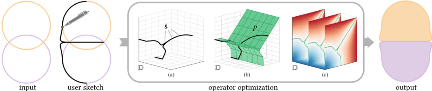
input user sketch operator optimization output
D D D
¯s P
Fig. 5. Given a pair of input primitives (two overlapping circles), the user sketches the desired resulting shape (a contact surface and a bulging effect). (a) The system generates a set of samples in the operator space D. (b) An operator template is fitted to the samples. (c) A dense regular sampling of the operator д is generated. The resulting operator, if applied to the initial pair of primitives, produces the desired behavior and can be applied wherever this effect is desired.
This can be understood as using different composition operators for different values ofθ. That is, according to whether the two gradi-ents are in opposite, orthogonal, matching directions, or anything in between. Undesired bulging can be resolved, and pre-contact deformations can be disabled, while in the other cases (intermediate angles) the transition can be kept smooth. Four specific problems of implicit modelling (bulging, locality, absorption, topology) were addressed by defining appropriate instances ofд [Gourmel et al. 2013]. The main challenges with gradient-based operators is that designing and fine tuning an operator to obtain some desired effect is a highly technical task, and not possible for non-expert end-users such as 3D artists and modelers. Thus, only predefined and fully parametrized operators can be provided to users and they have to be set in the system by experts.
Contributions. In this research, we address this usability-gap in com-position modeling. We propose a novel, interactive editing pipeline where the user sketches the desired behavior directly in 2D over one example, and an automatic optimization produces the correspond-ing operator, transparently to the user. Importantly, the design of an operator and its usage are kept orthogonal: an operator can be applied in any context (2D or 3D) where the same shape or behavior is desired, irrespective of the example where it was designed. Our method can be applied to any shape for which we can compute a signed distance function. The following contributions were nec-essary to achieve this result: (1) we introduce a new template to represent operators, which avoids the use of transfer functions such as those proposed in [Gourmel et al. 2013], and is suitable both in the design and in the application phases; (2) we present a way to map user-sketches into samples of operator-space D; (3) we observe that the problem of fitting this template to the samples can be cast as a deformable surface registration problem, and we identify suit-able regularizers; (4) we introduce the concept of non-commutative operators, which we show to be useful in certain scenarios, and fi-nally (5) we introduce some novel interesting applications for these operators.
2 RELATED WORK
Because of the ease of representing arbitrary and changing topolo-gies, CSG, blended and contact surfaces, implicit modeling has some advantages over traditional surface models [Marschner and Shirley
2015]. After presenting the previous works on controllable compo-sition operators and an overview of sketch-based implicit modeling, we review some potential applications of our operators.
On freeform operators. Over the years, several operators have been designed to try to fill the gap between their mathematical formu-lation and their manipuformu-lation by end-users. In aesthetic blends, Pasko and Savchenko [1994] optimize the three parameters of an algebraic blending operator to approximate a user’s sketch. More complex free-form 2D operators have been defined by blending implicit lines [Barthe et al. 2003] or by deforming a blending opera-tor [Barthe et al. 2004]. These operaopera-tors are subject to all the limi-tations solved by gradient-based operators and are not compatible with this operator formulation. Rather than focusing on the operator shape, Pasko et al. [2005] and Bernhardt et al. [2010] propose to localize the influence of blending operators on the combined objects by adding an additional 3D scalar function, placed automatically or user-defined. These approaches focus on the definition of where the blending should occur, and no explicit control is performed on the shape of the operator itself. As introduced by Gourmel et al. [2013], the shape of the gradient-based operators are defined by a set of 2D profile curves in cylindrical coordinates. This definition is unintuitive to manipulate and restricted in the variety of shapes it can produce. To achieve better skinning with accurate contact deformations, Vaillant et al. [2014] introduced gradient-based op-erators discretely computed in a 3D grid, 2D slice by 2D slice, by bi-harmonic interpolation of Dirichlet constraints at boundaries and additional constraints on the iso-value. Their specification relies on a lengthy trial and error process, consisting of editing a set of spline curves for a givenθ, as well as a trigonometric transfer function to non-linearly interpolate these curves along theθ axis. Furthermore, an interactive exploration is not feasible, as a re-computation of the computationally intensive fairing optimization is necessary on each update. Finally, their operator construction is tailored to a small set of effects useful in the targeted context (symmetric contacts and bulges), whereas our operators are generic. In our work, we enable the specification of freeform gradient-based operators at interactive rates through the use of 2D annotations, which directly describe the intended user-defined behavior.
Sketch based implicit systems. Sketches have long been recognized as a powerful tool for modeling [Igarashi et al. 1999]. Sketch-based im-plicit systems added the ability to do blending and CSG with volume
models in work such as [Alexe et al. 2005; de Araújo and Jorge 2003; Singh and Fiume 1998; Tai et al. 2004], and there have been several examples, including the popular ShapeShop by Schmidt et al. [2005]. [Singh and Fiume 1998] shares with us the idea that the final surface shape is modelled by a 3D curve. Closer to our proposal, Karpenko et al. [2002] built models using an implicit representation based on Radial Basis Functions. Their system used the input stroke to edit a mesh, which would in turn change the implicit representation. This implicitization approach changes the field locally according to the user’s edit. In the above approaches, sketches define the shape in one particular modeling instance. The input sketch in our system defines an operator, which is not tied to the context where it is defined, but can be applied wherever the user desires.
2.1 Applications
This work impacts several application domains, offering interesting contributions in each of them.
Character skinning. In the context of character skeleton-driven an-imations, composition operators have been used to achieve more realistic procedural skin distortions [Vaillant et al. 2013, 2014]. This is also a motivation for our work. With respect to these applications, our approach offers the ability for the designer to intuitively sketch the exact intended deformation (e.g. skin bulging) in one instance, and produce an operator which will reproduce that deformation in real time. This approach is analogous to example-based deformation schemes (see [Jacobson et al. 2014, Part 3] or [Shi et al. 2008]), but in our case, the exemplar sketch can be drawn in 2D, and the extracted operator can be directly applied to any other joint.
Font design. One potential application of our method is to assist font-design, where glyphs for each letter are the result of compo-sition operators in 2D from a pre-defined skeleton; similarly to [Suveeranont and Igarashi 2010]. The literature on font design is large, and covers many problems which are not addressed here, including automatic construction of the skeletons, or a consistent cross-parameterization for all glyphs, or even a generative manifold of all possible fonts; see [Campbell and Kautz 2014]. In pipelines where the skeletons of each glyph becomes available, our method offers the ability to control the shape of one glyph (e.g. serifs and joints), and apply it consistently to the entire type-face.
Botanical modeling. In the context of procedural synthesis of botani-cal models (both realistic and stylized), implicit models have been recognized early as suitable solution, due to their natural ability to recreate smoothly blending branching structures [Bloomenthal 1995; Galbraith et al. 2004; Hart and Baker 1996]. Using our tool, a user can simply trace the required shape to mimic the geometry of these features, and incorporate this effect into the operator.
3 METHOD OVERVIEW
A visual outline of our framework is illustrated in Figure 5. Our design process begins with the user placing two exemplar implicit primitives in a 2D sketch. The user then annotates the desired blend-ing behavior by sketchblend-ing a curve. Given this input, an automatic
input+sketches kernel+samples feedback
final operator
Fig. 6. Operator design feedback loop: because our pipeline (Fig. 5) has interactive response times, our system allows progressive refinement of the operator though successive strokes. Undesired blending artifacts (right) are corrected until a final operator is constructed which is capable of reproduc-ing the desired behavior.
system derives an operatorд by solving an inverse optimization problem; see Section 6. The resulting operator can then be used both to combine implicit curves in 2D and to combine surfaces in 3D. This observation is crucial, as it allows the user to simply work in 2D to produce operators for 3D modelling. This is even more relevant for the design of contact surfaces, which would otherwise be difficult to edit (or even just to visualize) in 3D, due to self-occlusions. Feedback loop. In many cases, a single set of user sketches are suf-ficient to fully determine the operatorд that produces the desired result; see Figure 5. For more complex cases, an iterative feedback loop can be used to refine the operator and at the same time observe its effect; see Figure 6. First, an operatorд0is constructed from an
initial sketch and automatically applied to the exemplar primitives. The resulting 2D drawing provides feedback to the user. The user can then add new sketches, and a new operator is produced from the union of all sketches. This is repeated until a satisfactory shape is returned to the user, limited only by the expressiveness of the gradient-based approach; see Section 7. In practice, we found we needed no more than three iterations. For the feedback loop to be
interactive, we need to ensure that our algorithms are computa-tionally efficient for the optimization of the operator and for its application.
4 BACKGROUND AND PRELIMINARIES
An implicit model (surface in 3D, or contour, in 2D) is defined by a scalar field-functionf , as the set of the points where f assumes a given iso-value. Following the convention from Bloomenthal and Wyvill [1997], we define the surface as S= {x ∈ Rn|f (x) = 0.5} which bounds an interior wheref (x) > 0.5. The field-functions of the primitives are, in turn, defined by their skeleton. For example, a sphere is generated by a point skeleton, and a capsule (a cylinder with hemispherical caps) by a line-segment skeleton. Any other shape can be used; see Figure 13,18 for some examples.
Support and continuity. The field has a value which decreases with the distance from the skeleton, according to a given falloff func-tion; see [Marschner and Shirley 2015, Ch. 22]. The area where the field function has valuesf (x) > 0 is denoted the support of the implicit object. Outside its support, the field function equals zero and the primitive has no influence on the composition operations. The support is compact, i.e. bounded; see Figure 7.
A central concern in implicit operator design is to ensure smooth blends and avoid normal discontinuities at the boundaries of the support. To this end, where functions such as min or max are used forд [Barthe et al. 2003], filter fall-off functions are required to be at leastC1. In our approach, where we fully control the composition functionд, this requirement can be completely dropped. Instead, we rely on functionsд with built-in smoothness, by defining appropriate value and derivative constraints at the boundaries of its domain D; see Section 6.3. This observation allows us to use any monotonic C0fall-off function for our primitives. In our examples we opt for a
simple linear function controlled by two intuitive parameters:R1,
the iso-value of the implicit model, andR2, the thickness of the
support;R1is mapped to 1/2 andR1+ R2to 0 (see Figure 7, top).
In the example of Figure 13, the curly branches are obtained by linearly interpolating two values ofR1along the skeletal curve of
the branch.
Intersection and difference. In this research, we concentrate on union composition operatorsд, which fuse two primitives into one in some prescribed manner, i.e.д always returns 1 when either of the first two parameters is 1, and 0 when both are 0. Generalization to intersections and differences is straightforward using the sameд:
дintersection(a,b, θ ) = 1 − д(1 − a, 1 − b,θ ) (3)
дdifference(a,b, θ ) = 1 − д(1 − a,b,θ ) (4)
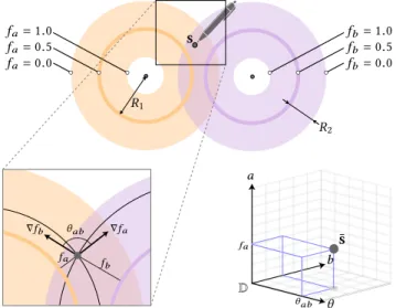
Implicit composition. The creation of complex geometry requires the composition of more than just two input functions. Following the ideas introduced by Wyvill et al. [1999], we employ different binary operators at each node of a tree, with primitive shapes at its leaves. For example, see Figure 1 where different operators are used in cascade. s fa= 0.0 fa= 0.5 fa= 1.0 fb= 0.0 fb= 0.5 fb= 1.0 R1 R2 ∇fa ∇fb fb fa θab D θ a b fa θab ¯s
Fig. 7. Top: a sample s is drawn in the intersection of the supports of the two primitives (bold colored lines) generated by the skeletons (black dots). Lower-left: a zoom-in around s: the gradients of the two field functions fa
and fbform an angle θ . Lower-right, the corresponding sample ¯s in the
operator’s domain D (see Eq. 5).
5 CAPTURING USER INPUTS
In our system, a pair of 2D primitives are arranged freely by the user; see Figure 6 for an example. The linear field functionsfaandfb
of the two primitives are expressed in closed form, and to the user, the two primitives are visualized as closed poly-lines. In Figure 7, we also visualize the supportsSa andSb of the two shapes. By construction, the target operator can only determine the resulting shape in the areaSa∩Sb, therefore user input strokes are restricted to be inside this area with a stencil mask. The user draws the desired shape of the resulting surface over the input primitives, with one or multiple sketches. For most experiments we employ parametric curves, but any drawing method such as the strokes in Figure 20c, can be used. As described below, this is possible as only a sampling of the sketches is required to derive an operator.
Sampling user input. From the user’s sketch, we extract a set of n samples {s1, . . . sN}. Each sample sn ∈ R2represents a position that the user expects the result/output surface to cross. As illustrated in Figure 7, for each sample snwe define a corresponding sample ¯sn
in the operator domain D: ¯sn= *. , an bn θn + / -= *. , fa(sn) fb(sn) ∠( ∇fa(sn) , ∇fb(sn) ) + / -(5)
Computations of ¯snfrom snare conveniently fast because functions fa and fb are available in closed form. Their gradient is either available in closed form or approximated by finite differences. The regressed operatorд evaluated at ¯snshould return the value (0.5), or in other wordsд(¯sn) = 0.5. Hence, after optimization, the designed
pa 1, 4
pb5, 4
Fig. 8. Our template is a surface P is made of two bi-quadratic patches, depicted with orange and violet control points – red ones are shared, creating a seam at the junction. This template is able to represent a variety of useful composition operators; see Section 6.2.
Sketches over 3D rendering. As a variation, sketches can be drawn over a 3D rendering of the implicit surfaces, seen from arbitrary viewing angle; e.g. see Fig. 17. In our prototype, the sketch is in this case assumed to lie on an plane parallel to the image at a predefined depth. Our framework requires no further adaptation to deal with this case. A more advanced interface could identify depth automati-cally, for instance by projecting the first point of the sketch on the shape, similarly to the sketch-based modeling interface proposed by Bernhardt et al. [2008].
6 FITTING THE COMPOSITION OPERATOR
The blending operator requires a 3D functionд to be defined over its entire space D, however samples collected from user’s strokes only define the behavior ofд in a small subset of D. On the other hand, many characteristics of the functionд are known a-priori, such as its general shape (Sec. 6.1), its continuity requirements (Sec. 6.2) and the values on the boundaries of D (Sec. 6.3). We approach this reconstruction problem in two steps: first, we identify the set of 0.5 values ofд, as a parametric surface P embedded in D, which is fitted to the samples (Sec. 6.4); we then compute a 3D lattice covering the domain ofд by propagating the iso-values in P (Sec. 6.5). The final operator is then evaluated by tri-linear interpolation of the lattice values.
6.1 The operator template
In previous work [Gourmel et al. 2013; Vaillant et al. 2013, 2014], д(a,b, θ ) is formulated as a collection of two dimensional functions for a few particular values ofθ, each independently defined as a curve defining the portions of the domain whereд evaluates to (0.5). These cases can be interpreted as axis aligned slices of the domain D. In our work, we conveniently represent the operatorд as one surface P embedded in D representing its (0.5) iso-value; see Figure 5b. This approach allows us to define a template for the surfaceP, designed to represent a wide class of useful operators: sharp unions (see Figure 8a), smooth blends (see Figure 8b), stretch (see Figure 8c), articulated contact (see Figure 8d) and asymmetric contact (see Figure 8e) amongst many others; see Figure 21.
Parametric representation. Our template for P is a surface made by a pair of third-order B-Spline patches, each withI × J control points, joined at their boundary and arranged as in Figure 8a. The surfaceP is fully determined by the positions of the control points
pa
i, j andpbi, j in D. We found I =J =5, for a total 45 distinct control
points, to provide the necessary expressiveness while avoiding ex-cessive redundancy. The continuity ofP at the junction is enforced by imposing ∀i ∈ [1..I] : pi, Ja = pi, Jb , while other boundary and regularization constraints will be discussed later.
6.2 Template expressiveness
A fundamental characteristic of our operator template lies in its ex-pressiveness. In particular, in Figure 21 we illustrate how, to the best of our knowledge, all results obtained by any composition operators which have been proposed in the literature can be expressed by our template. We now detail how several operators can be realized by properly deforming our template.
Sharp creases: if a sharp crease is desired in the transition be-tween the two operand surfaces (e.g. with union) thenд needs to breakC1continuity, and consequentlyP must have a normal discon-tinuity. In our template, this discontinuity is easily accommodated by construction at the junctions between the two splines. Smooth blends: ifд is required to generate surfaces without any sharp creases in the transition between the two operand surfaces, it needs to beC1continuous, and consequently, surfaceP must be smooth, including at the junction between splines. This can be easily obtained by aligning the points{pa
i, J −1,pi, Ja = pi, Jb ,pi, J −1b }.
Contact surfaces: another important feature of operators is the ability to produce contact surfaces at the transitions between the two primitives [Cani 1993; Vaillant et al. 2014]; see Figure 21efg. Our template can easily reproduce this situation by making the two patches partially coincide, thus realizing a non-manifold operator. Symmetry: many existing composition operatorsд are commuta-tive in their first two parameters, which in our setup makes surfaces P symmetric with respect to the a = b plane in D. Given ϕ : D → D is the planar mirroring transformationϕ(x,y, z) = (y, x, z), this can be easily obtained by enforcingpai, j = ϕ(pbi, j). Clearly, non-commutative operators, such as those in Figure 8d can also be rep-resented.
In summary, our template can recreate each of the features above. If required, our system allows users to explicitly enforce these condi-tions; however, it is not strictly necessary to do so, as surfaceP will naturally conform to these conditions whenever they are suggested by the user data as a result of the fitting process. This observation can aid the design of user interfaces based on our method.
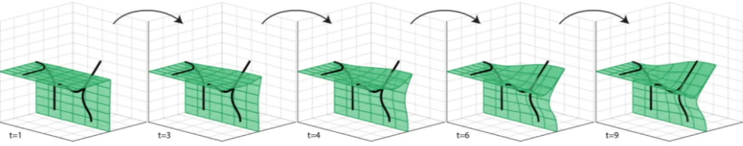
Fig. 9. We illustrate the sketches in operator space, and a few iterations of the operator registration optimization in Equation 10. The manifold surface folds onto itself to be able to reproduce a non-manifold configuration. At the same time, the way we enforce the symmetry constraint helps the optimization to avoid undesirable self-intersections. In this example, the optimization converged after 9 (two-steps) iterations; none of our experiemnts required more than 20.
6.3 Boundary conditions
Whenfa(p) = 0, the point p is outside the (compact) support of
fa, and hence beyond its range of influence, sofcshould exactly reproduce the values offb(p) to ensure C0continuity. Analogous considerations apply to thefb(p) = 0, fa(p) = 1 and fb(p) = 1
boundary planes of D, leading to the constraints: ∀θ, ∀a : д(a, 0, θ ) = a and д(a, 1,θ ) = 1
∀θ, ∀b : д(0,b, θ ) = b and д(1,b,θ ) = 1 (6) Further, to achieve (normal) shading smoothness at the boundaries of the supports, we must enforceC1continuity of the blending oper-ation by vanishing the derivatives:
∀θ, ∀a : ∂д∂b(a, 0, θ ) = 0, ∀θ, ∀b : ∂д∂a(0,b, θ ) = 0 (7)
Asθ represents the unsigned angle between the two gradient vectors, the functionд is implicitly mirrored at both ends [0, π] of its third parameter. Therefore, to achieveC1continuity we also impose:
∀a, ∀b : ∂д∂a(a,b, 0) = 0 ∀a, ∀b :∂д∂b(a,b, π ) = 0 (8) The constraints above translate into Dirichlet and Neumann bound-ary conditions for surfaceP, which can be conveniently expressed in terms of linear hard constraints on its control points. To enforce Equation 6, the control points on opposite ends ofP are constrained to lie on the two line segments at the boundary of D: (0.5, 0, θ ) and(0, 0.5, θ ). To enforce Equation 7 and Equation 8, the control points neighboring the boundaries ofP must be constrained to be vertically/horizontally aligned to the boundary control points.
6.4 Surface registration
In this phase, we fit the template parametric surfaceP to the col-lected samples ¯si.P maps each point uv = (u,v) of its 2D paramet-ric space into a positionP (uv) ∈ D, as determined by the control points {pk
i, j}. We start with an initial guess, which corresponds to
a union operator: a surfaceP where the two B-spline patches are simply planar and reciprocally orthogonal; see Figure 8a. We then non-rigidly register the template onto the samples following the approach in [Bouaziz et al. 2016]; see Figure 9. This optimization
consists of the alternation of two optimization steps: local: arg min
(uvn)
∥P (uvn) − ¯sn∥2, ∀¯sn (9) global: arg min
{pk i, j}
Ematch({pki, j}, {uvn}) + Epriors({pki, j}) (10)
That is, our local-global ICP optimization first computes closest-point projections, and then it globally modifies the surface control points, resulting in a non-rigid deformation of our surface. To ef-ficiently implement the local step, we first triangulateP (we em-ploy a resolution of 40 × 40), and use a regular volumetric grid to accelerate closest-point queries from ¯snto the triangles. We also constrain each of theI rows of control points to lie at a constant equally spacedθ values. The global step is implemented as one Least Squares minimization, as both energy terms are quadratic in the variables;Ematchrepresents the data-to-model error, whileEprior
accounts for shape-priors as well as optimization regularization. Fur-ther implementation details are available in our publicly released source code.
Matching term. The data-to-model error is computed as the aver-aged squared distances of samples from the tangent planes of their projections ontoP: Ematch= 1 N X n [nn·(¯sn−P (uvn))]2 (11) where nnis the normal atP (uvn). This point-to-plane metric leads
to better convergence compared to point-to-point errors. The term is a quadratic function of the variables, becauseP (uvn) and nnare both constants in the global step.
Priors. The prior energy includes several terms weighted by pa-rameters. These terms enforce: operator fairness, potential contact constraints, and regularization of the optimization:
Eprior = wfairEfair + wcontactEcontact + wtikhEtikh (12)
Fairness prior. We penalize oscillations in the surface with a bi-harmonic energy defined on the control pointspki, j:
Efair=
X
i, j
∥∆uvpi, jk ∥2 (13)
where∆uv represents the 2D Laplacian operator defined in the uv domain, adapted to have control vertices stored in matrix form
(a) symmetric (b) asymmetric (c) asymmetric
Fig. 10. (a) Symmetric contact operators a-la [Cani 1993] can be constructed through the enforcement of symmetry in D. We introduce asymmetric con-tact operators which can model phenomena as: (b) a rubber ball hitting a concrete wall, or (c) a steel ball hitting a sheet of softer metal.
pki, j. This regularizer has multiple advantages: (1) in under-sampled areas it ensures a smooth interpolation, (2) it prevents over-fitting and, (3) as the sketches only provide a sparse sampling in D, it regularizes our optimization ensuring the problem remains well-conditioned. Additionally, these fairness energies are known to penalize surface fold-overs [Botsch and Kobbelt 2004]. Following [Li et al. 2008], we start by a strong enforcement of fairness to avoid local minima, and progressively relax this constraint to allow the surface to eventually closely fit to the data. Specifically, we employ the weight scheduling wf air = 103·2−t+ 10−4, wheret is the iteration number.
Full-contact prior. When we detect that the user sketch corresponds to a full-contact (e.g. see Figure 21e, where two objects are fully separated by a contact interface), we also enable a prior that ensures the seam control points connecting the two patches of our template project on the boundary of the domain D:
Econtact= X (i, j) ∈S Y {nm} ∥ni·(pi, j−[1, 1, 1])∥2 n1= [1, 0, 0] n2= [0, 1, 0] (14)
Because of the multiplicationQ, this energy is non-linear, hence when computing its gradient we only enable the term that has the smallest point-to-plane residual.
Tikhonov regularization. As the fitting energy is linearized within each local step, we avoid overshooting with a mild Tickhonov regu-larizer, by settingwtikh= 10−3which penalizes displacements from
Fig. 11. Our sketched implicit operators are easily controllable by the artist. In this figure, we demonstrate several variants of two types of operators: (top) the smooth-union from [Gourmel et al. 2013], as well as the (bottom) implicit-contact from [Vaillant et al. 2013].
the previous solution: Etikh=
X
i, j,k
∥pki, j(t ) − pki, j(t − 1)∥2 (15)
6.5 3D-Lattice filling
Once the surfaceP describing the (0.5) iso-values of д is defined, the next step is to regularly sample its domain D and assign scalar values on each cell of the lattice. This is executed in three sub-steps: Step 1 – Initialization: we assign the voxels immediately surround-ingP with the signed distance from either of its two patches, by rasterizing them over the 3D lattice. Grid receiving two values are set to the greatest (i.e. most internal) one; this ensures robust evalu-ation when the two patches are coplanar, as in the case of contact operators, as the contact surface is in the interior of the object. Step 2 – Boundary assignment: for eachθ slice of D, we assign the values the four sides {(0, ∗, θ ), (1, ∗, θ ), (∗, 0, θ ), (∗, 1, θ )} accord-ing to the boundary constraints in Equation 6.
Step 3 – Value propagation: the values assigned in the previous two sub-steps are diffused over the remaining portions of D by solving a bi-harmonic fairing optimization (where the values set in previous steps act as hard constraints).
Step 3* – Efficient value propagation: Step 3 is time-consuming, as its complexity is cubic in the linear resolution of the lattice. For-tunately, this is only necessary when the operator must be used in
k=0.2 k=1.2 k=0.4 k=0.6 k=0.8 k=1.4 k=1.6 k=1.8 k=0.0 k=1.0 дa дb
Fig. 12. We define two symmetric contact operators through the sketches in the first column, generating дaand дbresulting in the composition visualized in
the second column. By leveraging the consistency in the operator’s parameterization, other operators can be generated as дk = (1 − k)дa+ kдb; for k ∈ (0, 1)
we obtain operators whose behavior is intuitively interpolated (top), while extrapolation can be obtained for values of k outside of this range (bottom).
successive compositions. When only two objects need to be com-bined, as during during the operator design process, only the lattice values surrounding the (0.5) surface are relevant, and the other ones can be safely disregarded. This observation drastically reduces the latency of the feedback loop, effectively enabling the interactive design discussed in Section 3.
7 EVALUATION
We evaluate our work by verifying the expressiveness of our sketched operators, the controllability of results, as well as the possibility of interpolating between different operators.
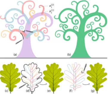
R (1)1 R (2)1
Fig. 13. Modeling quasi-biological structures such as a procedural curly-tree (top) and an oak leaf (bottom). We show the input primitives and the artist sketches (a), as well as the composition result (b). The leaf design starts with the placement of a few skeletal branches, from which the leaf boundary (d) or a single sketch (f) can be used to design a corresponding blending (e,g).
Expressiveness. We empirically validate our approach by demon-strating a variety of effects. We collect all the fundamental types of implicit blending operator that have been proposed in the literature (to the best of our knowledge), and verify that our template can be optimized to express the same behavior. To this extent, Figure 21 reports a number of representative images from the literature, and the 2D sketch necessary to generate the desired operator. We vi-sualize the optimized (deformed template) operator, and the result of its application on the 2D input geometry. We also show how all our custom operators extend to 3D in a completely straightforward fashion. Our sketches can be used to: (a) represent traditional CSG operations [Sabin 1968]. (b) smoothly blend two primitives [Blinn 1982] and [Ricci 1973], (c) perform bulge-free blend [Gourmel et al. 2013]. (d) avoid premature-blending [Gourmel et al. 2013], (e) model bulge-on-contact between two objects [Cani 1993], as well as (f,g) represent the partial-contact from implicit-skinning [Vaillant et al. 2013]. In fact, the expressiveness of our operators go beyond the capabilities of those proposed in the literature, and allows us to extend the contact operators pioneered by [Cani 1993], towards the representation of asymmetric-contact, without having to edit the input scalar fields; see Figure 10.
Controllability and interpolation. As our algorithm receives user sketches as input, the behavior of the operator is easily controllable. In Figure 11, we demonstrate how several variants of blending and contact operators can be faithfully reproduced by specifying the desired behavior with a simple 2D sketch. Another form of compo-sition control can be obtained by blending two distinct compocompo-sition operators. As illustrated in Figure 8, the topology of the template is consistent across all of our examples. This allows us to blend operators through simple linear interpolation/extrapolation of its control points; see Figure 12.
8 APPLICATIONS
We present several example applications that benefit from the sketch-based generation of blending operators. The input sketches can either be drawn freely, or rotoscoped over annotated images.
Fig. 14. A rubber ball that elongates according to its velocity, and squishes when it comes into contact with the floor in an artist-defined fashion.
Botanical modeling. Our curly tree shown in Figure 13-top is inspired by the images returned by the search query “curly tree”. The place-ment and shape of primitives can be produced by any procedural grammar-based algorithm [Lienhard et al. 2017]. Our technique allows for the automatic generation of controllable smooth-blends connecting branches to each other. Two user strokes are sufficient to define the desired operator behavior, and the result is applied to a large quantity of compositions. In this case a single operator was used, but variability can be easily achieved by interpolating multiple variants (see Figure 12) with random weights; a 3D example of this process is visualized in Figure 17. In Figure 13-bottom, we apply our sketch-driven operators to the procedural generation of botanical leaves. The skeletal structure of the leaf is generated via an appro-priate grammar, as in the tree example. In this setup we experiment with two different sketches. In Figure 13d, the sketch is the entire boundary of the leaf from Figure 13c, while in Figure 13f the user has sketched the operator himself. The optimized operators result in blended geometry closely mimicking the geometry of natural leaves (we superimpose the original texture to make this more apparent). Approximating contact behavior. In Figure 14, we approximate the behavior of a rubber ball in motion through the design of two oper-ators. The first distorts the shape of the ball, modeled via a “ghost” primitive whose position is determined according to the velocity vector. The second operator captures the contact behavior between the projectile and the deformable wall. In our stop-motion illustra-tion the distorillustra-tion was interpolated, while the contact behavior was
no effect mercury water cross-section
Fig. 15. Applying implicit contact operators to the output of a fluid simu-lation produces a noticeable improvement in visual quality. This effect is efficient to apply, as many fluid solvers represent liquids with implicit func-tions. While our operator can apply to any geometry, we choose a simple and familiar scene that can be more easily appreciated.
simple union hydrophobic operator hydrophilic operator
Fig. 16. The same sphere lying in proximity of a plane can produce contact deformations simulating both hydrophobic and hydrophilic deformations according to the type of asymmetric blending designed by the artist.
extrapolated. Asymmetric contact operators can also be used to approximate the fine-scale behavior of liquids when they come in contact with surfaces coated with different materials; see Figure 16. Obtaining such effects through fluid dynamic simulation is difficult as it requires a volume-preserving solver and careful implementa-tion of boundary condiimplementa-tions; [Wang et al. 2005]. Such effects, due primarily to surface tension, can also be approximated by evaluating a curvature flow on surfaces [Thürey et al. 2010]. Our approach approximates these effects without the need for complex physical simulation, and allows their application in a lightweight fashion as a post-processing step; see Figure 15.
Implicit vector font design. Another application is the creation of font libraries, in particular as our method allows a user to explore the design space interactively; see Figure 18. In this example, we use multiple sketches on the letter T and A to derive one operator, re-producing the desired behavior for orthogonal and non-orthogonal configurations. Again, the composition operators is derived from a few exemplars and then applied to all other cases. The user can explore different variants for a character, and export the blend-ing operator to create a self-consistent font library. An example showcasing the extensibility of font design to three dimensions is illustrated in Figure 1. In typography, another common task is the application of serifs to characters. In this example, we apply our composition operators to this task. To achieve this, the yellow primitive removes ink from the pink primitive, with a difference operation (see Equation 4). This setup provides the user with a fast and easy method to prototype different serif styles, as illustrated. Because our operator kernelP is an algebraic surface, the operator д can be generated at any scale; hence, as long as the input primitives can also be expressed in algebraic form (as in the examples shown), our fonts can be synthesized at any desired resolution.
9 CONCLUSIONS
Implicit models have recently re-emerged as a powerful model-ing technique with the introduction of gradient-based operators [Gourmel et al. 2013], solving several problems that were often re-garded as intrinsic to implicit modelling. While more expressive the new operators are difficult to control. In this work we have introduced a solution based on an inverse approach which allows sketch-based design of new operators. The designer directly de-scribes the desired effect of the operator on the resulting surface, without having to understand the mathematics of the operator space. We have shown a number of practical applications demonstrating that our approach enables a designer to quickly take advantage of the powerful nature of implicit modelling. In addition, our approach
blending with simple union blending a-la metaball sketched blend
(a) (b) (c) (sketch) (c-zoom)
(a-zoom) (b-zoom)
Fig. 17. (a) A procedural tree generated by [Lienhard et al. 2017] as a collection of sphere-meshes [Tkach et al. 2016]. (b) a traditional blending operator results in unwanted bulges (e.g. Blender’s metaballs), (c) our blending operator designed via a simple 2D sketch is propagated to all branches in the hierarchy.
also serves as a conceptual tool to investigate the space of possible gradient-based operators. Using it, we were able to create a new class of non-commutative operators; see Figure 10.
Limitations and future work. The expressiveness of the gradient-based implicit operators, defined as in Equation 1, while being superior to the traditional 2D operators, is still insufficient for some cases. For example, regardless of how it is designed, no such operator can reproduce the shape sketched in Figure 20a. This situation arises when different sketches define constraints that are conflicting in the operator domain. For instance, in Figure 20a, the top left and top right fields are mirrored by vertical symmetry. In that case, pairs of symmetric points in the Euclidean space define the same point in the operator space. If two different sketches are defined in each side, as the sharp angle in the top left and the blend in the top right, the result of our fitting process provides an “average” shape that
Fig. 18. (top) Multiple sketches on different primitives are used to synthesize a blending operator that can be used to produce font variations as well as an entire “infinite resolution” font family. (bottom) Sketching negative blends to apply a “serification” effect.
can be unsatisfactory when the input sketches are too different. In the future we intend to further generalize blending operators, to augment the range of achievable effects; e.g. anisotropic operators. We have shown that operators based on a 3D domain can be designed with 2D sketches; the same approach could be applied to higher dimensional operators, which have additional parameters. The applicability of our custom operators is not limitless either. While they can be applied to any implicit model, the fall-off functions are assumed to be roughly similar, otherwise the shape produced by the operator can diverge arbitrarily from the user’s sketch; e.g. if one of the two support radiiR2is vastly different.
Another inherited limitation of gradient-based operators is that they can generate artifacts where scalar fields exhibit gradient disconti-nuities. This rarely occurs in practice.
A different issue is that our operators, in general, lack associativity. Associative binary operators are desirable because they constitute a natural definition of operators working on any number of operands. An interesting open question is whether the input primitives could be inferred along with the operators. Finally, it would be interesting to handle a sketch on more than two overlapping primitives.
Fig. 19. The leaf geometry from Figure 13e is lifted to 3D, and combined with a set of randomly placed spheres through the hydrophobic contact operator from Figure 16.
C1
C0
(a) (b) (c)
Fig. 20. (a) The sketches result in conflicting samples in the operator domain D, revealing a limitation in expressiveness of gradient-based operators; the user can nonetheless opt for an operator exhibiting either C0or C1
continuity to approximate its input. (b) The smooth nature of the operators is unsuitable to capture dense high-frequency information, which is simply ignored as noise by the optimization. (c) On the other hand, this could be thought of as an advantage, as an artist can draw multiple noisy strokes, and obtain an operator fitting them well.
ACKNOWLEDGMENTS
We would like to thank the inspiration provided by the McGill University Bellairs Institute, Chris Wojtan and Alyn Rockwood for their insightful feedback, Stefan Lienhard for the procedural models, François-Xavier Nhieu for his work on the teaser image, Daniel Rebain and Nicolas Guillemot for proofreading the paper, and Angela di Sante for her help with video compositing.
REFERENCES
A. Alexe, L. Barthe, M.P. Cani, and V. Gaildrat. 2005. Shape modelling by sketching using convolution surfaces. In Pacific Graphics (Short Papers).
L. Barthe, N. A. Dodgson, M. A. Sabin, B. Wyvill, and V. Gaildrat. 2003. Two-dimensional Potential Fields for Advanced Implicit Modeling Operators. Computer Graphics Forum 22, 1 (2003), 23–33. https://doi.org/10.1111/1467-8659.t01-1-00643 Loïc Barthe, Brian Wyvill, and Erwin De Groot. 2004. Controllable binary csg operators
for soft objects. International Journal of Shape Modeling (2004).
Adrien Bernhardt, Loic Barthe, Marie-Paule Cani, and Brian Wyvill. 2010. Implicit blending revisited. Proc. of Eurographics, Computer Graphics Forum 29, 2, 367–376. A. Bernhardt, A. Pihuit, M. P. Cani, and L. Barthe. 2008. Matisse: Painting 2D Regions for Modeling Free-form Shapes. In Proc. of the Fifth Eurographics Conference on Sketch-Based Interfaces and Modeling (SBM’08). Eurographics Association, 57–64. James F Blinn. 1982. A generalization of algebraic surface drawing. ACM transactions
on graphics (TOG) 1, 3 (1982), 235–256.
Jules Bloomenthal. 1995. Skeletal Design of Natural Forms. Ph.D. Dissertation. University of Calgary.
Jules Bloomenthal and Brian Wyvill (Eds.). 1997. Introduction to Implicit Surfaces. Morgan Kaufmann Publishers Inc.
Mario Botsch and Leif Kobbelt. 2004. A remeshing approach to multiresolution modeling. In Proc. of the Eurographics/ACM SIGGRAPH symposium on Geometry processing. Sofien Bouaziz, Andrea Tagliasacchi, Hao Li, and Mark Pauly. 2016. Modern
Tech-niques and Applications for Real-Time Non-rigid Registration. Proc. SIGGRAPH Asia (Technical Course Notes) (2016).
Neill D. F. Campbell and Jan Kautz. 2014. Learning a Manifold of Fonts. ACM Trans. on Graphics (TOG) (2014).
Marie-Paule Cani. 1993. An Implicit Formulation for Precise Contact Modeling Between Flexible Solids. In ACM Trans. on Graphics (Proc. of SIGGRAPH).
Bruno de Araújo and Joaquim Jorge. 2003. BlobMaker: Free-Form Modelling with Variational Implicit Surfaces. In 12th Encontro Português de Computação Gráfica. Callum Galbraith, Lars Muendermann, and Brian Wyvill. 2004. Implicit Visualization
and Inverse Modeling of Growing Trees. (2004).
Olivier Gourmel, Loic Barthe, Marie-Paule Cani, Brian Wyvill, Adrien Bernhardt, Math-ias Paulin, and Herbert Grasberger. 2013. A Gradient-based Implicit Blend. ACM Trans. on Graphics (TOG) (2013).
John C Hart and Brent Baker. 1996. Implicit modeling of tree surfaces. In Proc. EG workshop on implicit surfaces.
Christoph Hoffmann and John Hopcroft. 1985. Automatic surface generation in com-puter aided design. The Visual Comcom-puter 1, 2 (1985), 92–100.
P. C. Hsu and C. Lee. 2003. Field Functions for Blending Range Controls on Soft Objects. Proc. of Eurographics, Computer Graphics Forum 22, 3 (2003), 233–242.
Takeo Igarashi, Satoshi Matsuoka, and Hidehiko Tanaka. 1999. Teddy: A Sketching Interface for 3D Freeform Design. In Proc. of the 26th Annual Conference on Computer Graphics and Interactive Techniques.
Markus Ihmsen, Jens Orthmann, Barbara Solenthaler, Andreas Kolb, and Matthias Teschner. 2014. SPH Fluids in Computer Graphics. In Eurographics 2014 - State of the Art Reports.
Alec Jacobson, Zhigang Deng, Ladislav Kavan, and JP Lewis. 2014. Skinning: Real-time Shape Deformation. In ACM SIGGRAPH 2014 Courses.
Olga Karpenko, John F Hughes, and Ramesh Raskar. 2002. Free-form sketching with variational implicit surfaces. In Computer Graphics Forum.
Hao Li, Robert W Sumner, and Mark Pauly. 2008. Global Correspondence Optimization for Non-Rigid Registration of Depth Scans. In Computer graphics forum, Vol. 27. Wiley Online Library, 1421–1430.
S. Lienhard, C. Lau, P. Müller, P. Wonka, and M. Pauly. 2017. In Design Transfor-mations for Rule-based Procedural Modeling. Computer Graphics Forum (Proc. of Eurographics).
Ives Macedo, Joao Paulo Gois, and Luiz Velho. 2011. Hermite radial basis functions implicits. In Computer Graphics Forum, Vol. 30. Wiley Online Library, 27–42. Steve Marschner and Peter Shirley. 2015. Fundamentals of computer graphics (4th ed.)
Chapter 22 Implicit Modeling. A. K. Peters/CRC Press, Ltd.
Alexander Pasko and Valery Adzhiev. 2004. Function-based shape modeling: mathe-matical framework and specialized language. In Automated Deduction in Geometry, Lecture Notes in Artificial Intelligence 2930.
Alexander Pasko, Valery Adzhiev, Alexei Sourin, and Vladimir Savchenko. 1995. Func-tion representaFunc-tion in geometric modeling: concepts, implementaFunc-tion and applica-tions. The Visual Computer (1995).
Alexander A Pasko and Vladimir V Savchenko. 1994. Blending Operations for the Func-tionally Based Constructive Geometry, In Set-theoretic Solid Modeling: Techniques and Applications. CSG 94 Conference Proc..
Galina I. Pasko, Alexander A. Pasko, and Tosiyasu L. Kunii. 2005. Bounded Blending for Function-Based Shape Modeling. IEEE Comput. Graph. Appl. 25, 2 (2005), 36–45. A.A.G. Requicha and H.B. Voelcker. 1977. Constructive Solid Geometry. Production
Automation Project, University of Rochester.
A Ricci. 1973. A constructive geometry for computer graphics. Comput. J. 16, 2 (1973), 157–160.
A. P. Rockwood. 1989. The Displacement Method for Implicit Blending Surfaces in Solid Models. ACM Trans. on Graphics (TOG) (1989).
M.-A. Sabin. 1968. The use of potential surfaces for numerical geometry. British Aircraft Corporation, Weybridge, UK, Technical Report No. VTO/MS/153 (1968).
Ryan Schmidt, Brian Wyvill, Mario Costa-Sousa, and Joaquim A. Jorge. 2005. ShapeShop: Sketch-Based Solid Modeling with the BlobTree. In Proc. 2nd Eurographics Workshop on Sketch-based Interfaces and Modeling. Eurographics.
Xiaohan Shi, Kun Zhou, Yiying Tong, Mathieu Desbrun, Hujun Bao, and Baining Guo. 2008. Example-based dynamic skinning in real time. In ACM Trans. on Graph-ics (TOG).
Karan Singh and Eugene Fiume. 1998. Wires: A Geometric Deformation Technique. In Proc. of SIGGRAPH’98. ACM, New York, NY, USA, 405–414.
Rapee Suveeranont and Takeo Igarashi. 2010. Example-based Automatic Font Genera-tion. In Proceedings of the 10th International Conference on Smart Graphics (SG’10). Springer-Verlag, Berlin, Heidelberg, 127–138. http://dl.acm.org/citation.cfm?id= 1894345.1894361
C. Tai, H. Zhang, and J. Fong. 2004. Prototype modeling from sketched silhouettes based on convolution surfaces. In Computer Graphics Forum, Vol. 23. 71–83. Nils Thürey, Chris Wojtan, Markus Gross, and Greg Turk. 2010. A multiscale approach to
mesh-based surface tension flows. In ACM Trans. on Graphics (Proc. of SIGGRAPH). Anastasia Tkach, Mark Pauly, and Andrea Tagliasacchi. 2016. Sphere-meshes for
real-time hand modeling and tracking. ACM Trans. on Graphics (Proc. of SIGGRAPH Asia) (2016).
Rodolphe Vaillant, Loïc Barthe, Gaël Guennebaud, Marie-Paule Cani, Damien Rohmer, Brian Wyvill, Olivier Gourmel, and Mathias Paulin. 2013. Implicit Skinning: Real-time Skin Deformation with Contact Modeling. ACM Trans. on Graphics (Proc. of SIGGRAPH) (2013).
Rodolphe Vaillant, Gäel Guennebaud, Loïc Barthe, Brian Wyvill, and Marie-Paule Cani. 2014. Robust Iso-surface Tracking for Interactive Character Skinning. ACM Trans. on Graphics (Proc. of SIGGRAPH Asia) (2014).
Huamin Wang, Peter J Mucha, and Greg Turk. 2005. Water drops on surfaces. In ACM Transactions on Graphics (TOG), Vol. 24. ACM, 921–929.
Brian Wyvill, Andrew Guy, and Eric Galin. 1999. Extending the csg tree. warping, blending and boolean operations in an implicit surface modeling system. In Computer Graphics Forum, Vol. 18. Wiley Online Library, 149–158.
(a) union [Sabin 1968] (b) smo oth blend [Blinn 1982] (c) bulge-fr ee blend [Gourmel et al. 2013] (d) blend+union [Gourmel et al. 2013] (e) contact+bulge [Cani 1993] (f ) skinning [V aillant et al. 2014] (g) skinning+bulge [V aillant et al. 2014]
target image primitives+sketches optimized operator applied in 2D applied in 3D
Fig. 21. Our sketch-based construction method can be used to effortlessly produce every gradient blend operator proposed in past literature (pioneering citation is indicated). Starting from images depicting the final results of each operator (leftmost column), we simply sketched over 2D contour (second column). From these sketches, our system reverse-engineers the operator (central column). This can be applied (in 2D or 3D alike, rightmost columns) to reproduce the same results. Our target images are courtesy of [Gourmel et al. 2013] and [Vaillant et al. 2014].