HAL Id: hal-03053628
https://hal.archives-ouvertes.fr/hal-03053628
Submitted on 11 Dec 2020
HAL is a multi-disciplinary open access
archive for the deposit and dissemination of
sci-entific research documents, whether they are
pub-lished or not. The documents may come from
teaching and research institutions in France or
abroad, or from public or private research centers.
L’archive ouverte pluridisciplinaire HAL, est
destinée au dépôt et à la diffusion de documents
scientifiques de niveau recherche, publiés ou non,
émanant des établissements d’enseignement et de
recherche français ou étrangers, des laboratoires
publics ou privés.
Epitaxial growth of TbFe 2 on piezoelectric LiNbO 3
Z-cut
Vincent Polewczyk, Michel Hehn, Arnaud Hillion, Sylvie Robert, Pascal
Boulet, Karine Dumesnil
To cite this version:
Vincent Polewczyk, Michel Hehn, Arnaud Hillion, Sylvie Robert, Pascal Boulet, et al.. Epitaxial
growth of TbFe 2 on piezoelectric LiNbO 3 Z-cut. Journal of Physics: Condensed Matter, IOP
Publishing, 2020, 32 (23), pp.235803. �10.1088/1361-648X/ab75ff�. �hal-03053628�
Epitaxial growth of TbFe
2on piezoelectric LiNbO
3Z-cut
V. Polewczyk1, M. Hehn1, A. Hillion1, S. Robert1, P. Boulet1 and K. Dumesnil1 1Institut Jean Lamour (UMR 7198), CNRS-Université de Lorraine, 54000 Nancy, France
The strongly magnetostrictive TbFe2 compound has been epitaxially grown on Z-cut Lithium Niobate (LiNbO3)
substrates after the deposition of various buffer layers (Mo, Ti and Ti/Mo). Detailed and combined RHEED and X-ray analysis permitted to unravel the in-plane and relative Orientation Relationships (OR) of the different materials in the system. Despite the use of different templates with different structural orders, similar final OR
are eventually found between the piezoelectric substrate and the magnetic layer. The structural and magnetic properties are analyzed in order to get a TbFe2 layer of optimum quality to build a magnetostrictive/piezoelectric
hybrid system with efficient strain mediated coupling. Such systems are of interest for the development of magnetic sensors as well as for the electric control of magnetization.
I. Introduction
The coupling of magnetic and electric properties in a unique system is of paramount interest to achieve the electric control of magnetization. Unfortunately, single-phase materials, i.e. intrinsic multiferroic, generally exhibit a weak coupling and therefore little magnetic (electric) response to electric (magnetic) excitation. Hybrid multiferroic systems combining magnetostrictive and piezoelectric materials are good alternatives since the strain-mediated coupling between magnetic and electrically-induced mechanical behaviors could overcome the performances observed in intrinsic multiferroic compounds. Such systems are rising an increasing interest for the development of magnetic sensors [ELH16, MIS17, POL17], as well as for the electric control of magnetization and magnetization dynamics [DU19, THE16, WEI11]. Among possible magnetostrictive materials, Terfenol (TbFe2)
is a serious candidates due to its record room temperature magnetostriction (≈ 2000 ppm) [CLA80], but, up to now, the hybrid systems based on Terfenol could not fully benefit from such performance, most likely because of the amorphous or polycrystalline form of the magnetic compound [ATU10, PER09, RYU02].
From our knowledge, only one study focused on this aspect and reported on the epitaxial growth of TbFe2 on a
LiNbO3 (LN) substrate by Molecular Beam Epitaxy (MBE) [HUT99]. A Z-cut orientation has been chosen since
its high symmetry is suitable for the epitaxial growth of the buffer layers and the subsequent TbFe2 Laves phase
structure. The authors conclude to the possible epitaxial growth of the compound along the [111] direction provided the previous deposition of a double Ti/Mo buffer forming a chemical barrier and initiating the growth. The use of a complex thick template however presents several drawbacks, in particular a possible reduction of the mechanical coupling between the substrate and the top magnetostrictive layer and the difficulty to extend the growth process to LN substrates with different orientations that would be of stronger interest due to larger piezoelectric responses.
The point of the current study is thus to explore in further details the possible epitaxial growth of TbFe2 on LN
substrates with the high symmetry Z-cut orientation. Our goal was to revisit the possible buffer layers in carefully comparing single Mo and Ti layers with the double Ti/Mo template. First in performing a detailed structural study of the buffer layers themselves and then in analyzing structural and magnetic characteristics of the eventually deposited TbFe2. A deeper insight into epitaxial Orientation Relationships (OR), the possible occurrence of
multiple domains and the incidence on magnetic properties are important aspects for the sought coupling between piezoelectric and magnetostrictive responses.
II. Growth of the buffer layer(s)
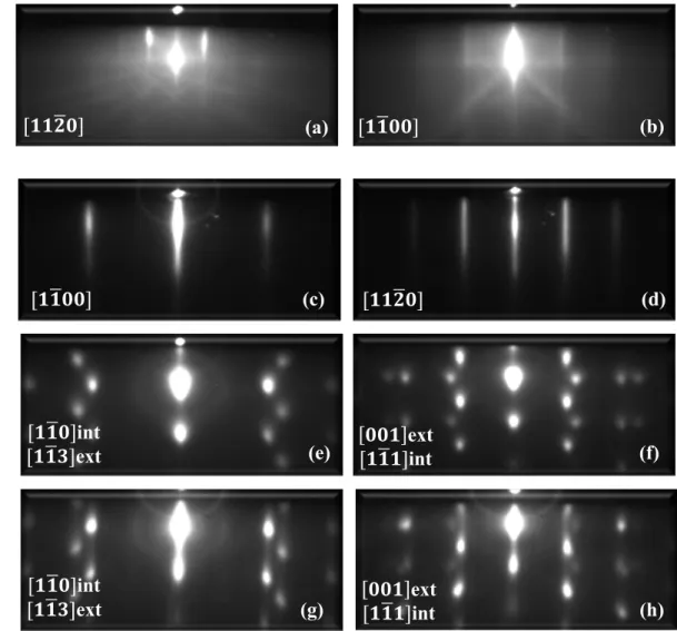
As mentioned in introduction, the LN substrates used in this study are orientated with the hexagonal lattice c-axis perpendicular to the surface, i.e. with (0001) planes parallel to the surface. These are commonly called LN Z-cut substrates. Before any deposition experiments, the LN substrates are first cleaned with acetone, isopropanol, rinsed with de-ionized water and outgassed in Ultra High Vacuum (UHV) during one hour at 500 °C. This moderate temperature should prevent from any deterioration related to the LN low stability observed at higher temperature in previous studies [HUT99]. At 500°C, no change in the LN RHEED patterns and no pressure increase (stable in the low 10-10 Torr range) were observed. Typical LN RHEED patterns collected after the preparation process and
prior to any deposition are presented in Figure 1 (a) and (b) along two different azimuths rotated by 90°. The presence of Kikuchi lines confirms the good crystalline quality of the surface. The analysis of the inter-streaks distances and the surface symmetry allows us to identify the main in-plane 〈1120〉 and 〈1100〉 azimuthal directions.
The deposition temperatures have been optimized for the various templates. As proposed by Huth and Flynn [HUT99], the Ti deposition is performed with the substrate kept at 100 °C, the structural quality decreasing for higher temperatures. The Mo deposition temperature on sapphire substrates is generally reported as optimal above 700 °C [KWO86, HUT98a, HUT98b]. The stability issues of LN at high temperature led us to test lower deposition temperatures in the [400 °C - 800 °C] range, which yields an optimal quality (as checked by X-ray diffraction) for 450°C. This Mo deposition temperature has been also used for the deposition of Mo on Ti. Temperatures above 500 °C systematically led to adhesion problems of Mo on Ti with the occurrence of cracks and eventually the partial removal of the layer after the deposition process. Deposition rates in the [0.01 nm.s-1 – 0.1 nm.s-1] range
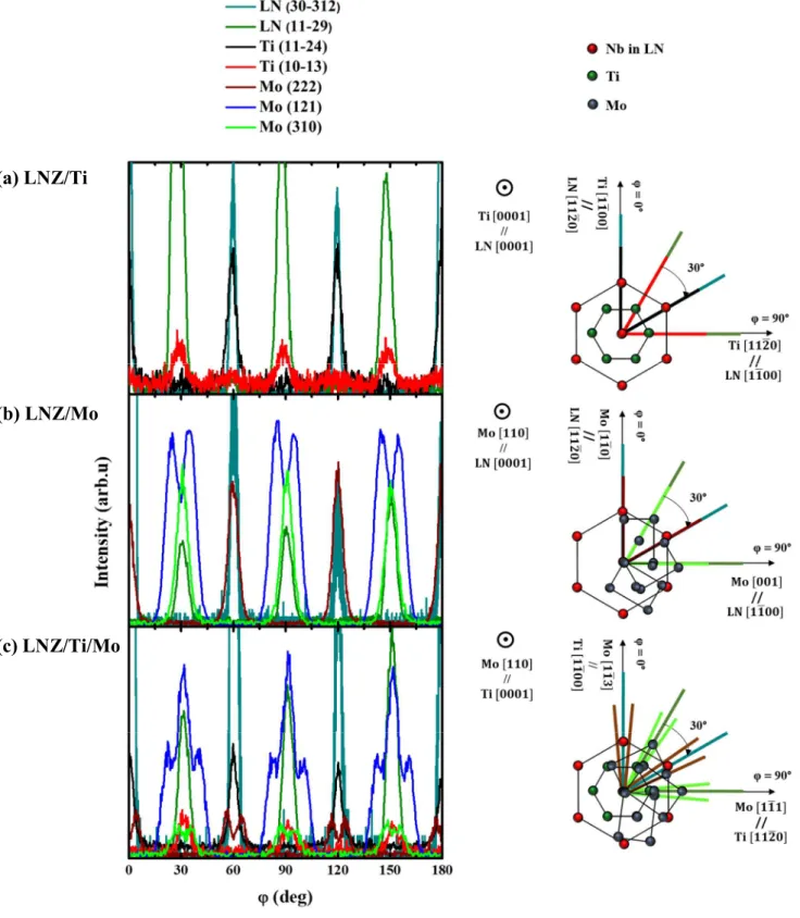
were tested with no significant influence of this parameter. The results presented here concern 50 nm thick layers. The quality, structural characteristics and epitaxial relationships have been analyzed in combining the RHEED observations (Figure 1) and X-ray scattering experiments, especially φ scans for selected Asymmetrical Reflections (AR) (Figure 2). The Table 1 presented in appendix recalls which in-plane direction can be identified via the measurement of a given asymmetrical reflection.
The Ti RHEED patterns for LN/Ti (Figure 1 (c) and (d)) exhibit continuous streaks characteristic of a relatively smooth surface. Two successive RHEED patterns measured in rotating the sample around its normal direction reveal an hexagonal symmetry with two main directions separated by 30°. From the relative inter-streak distances, it is possible to confirm the 1.73 ratio expected from the < 1100 > and < 1120 > azimuthal directions in the (0001) plane.
For LNZ/Mo and LNZ/Ti/Mo (Figure 1 (e)-(h)), two typical Mo RHEED patterns rotated by 30°, each being reproduced every 60°, are observed. In both cases, there is a clear superposition of several diffraction patterns that could not be separated in changing the azimuth angle and that could not be simply identified. In addition, streaks are dotted, revealing a 3D character, i.e. a surface roughness.
Specular θ/2θ X-ray scattering scans (not presented here) performed for the buffer layers deposited on LNZ [POL18] mainly confirm that the low surface free energy planes of Ti and Mo are parallel to the surface:
(0001) Ti // (0001) LN (110) Mo // (0001) LN (110) Mo // (0001) Ti // (0001) LN
The rocking curves across the main Bragg peaks exhibit a Full Width at Half Maximum (FWHM) of 0.8° for (0002) Ti on LNZ, of 1° and 0.9° for (220) Mo on LNZ and LNZ/Ti respectively, which is a sign a relatively good quality. The coherence length along the growth direction is approximatively 25nm for single Ti and Mo on LNZ and 32 nm for Mo in LNZ/Ti/Mo.
φ scans for selected AR on LNZ/Ti (Figure 2 (a)) show, as expected, that 30° separate the AR related to < 1100 > (Ti (11-24)) and < 1120 > (Ti (10-13)) plane directions. The comparison of LN and Ti AR shows that the in-plane OR, as already evidenced by RHEED patterns, are:
Ti [1120] // LN [1100] Ti [1100] // LN [1120]
This 30° rotation between LN and Ti basal planes lattices enables a relatively good crystalline match, with a 1 Ti : 1 LN coincidence between atomic rows perpendicular to the LN [1120] direction and a 3 Ti : 1 LN coincidence between atomic rows perpendicular to the LN [1100] direction.
For the Mo template deposited on LNZ (Figure 2 (b)), the φ scans permit to identify three < 001 > directions (Mo (310) rotated by 60°) and three < 110 > directions (Mo (222) rotated by 60°) over the 180° angular range. These reveal the occurrence of three (110) domains rotated by 60° and the following in-plane OR respect to the LN lattice:
Mo [001] // LN [1100] Mo [110] // LN [1120]
The RHEED patterns (Figure 1 (c and d)) thus correspond to the resulting superposition of the diffraction patterns since the in-plane spread of the crystal orientation doesn’t allow a clear separation between these. The ratio between inter-streaks distances have been checked to be 1.41 for [110] and [001] azimuths (Figure 1 (c)) and 1.92 for [111] and [113] azimuths (Figure 1 (d)).
Concerning the growth of Mo on (0001) Ti (Figure 2 (c)), six < 001 > and six < 110 > directions can be identified over the 180° angular range, revealing the formation of six (110) domains on Ti. In this case, the comparison of φ angles related to Ti and Mo AR leads to the following in-plane OR between Mo and Ti lattices:
Mo [111] // Ti [1120] // LN [1100] Mo [113] // Ti [1100] // LN [1120]
The OR between the Mo (110) and the LN (0001) or the Ti (0001) planes (sketched on the right of Figure 2 (b) and 2 (c)) can be discussed in the frame of the rigid-lattice theory usually invoked to predict the orientations between (110) bcc and (111) fcc lattices (or (0001) hcp lattice) [PAI90]. The OR should depend on the ratio between nearest neighbor distances in the surface plane. The most likely orientations are those for which densely-packed rows in (111) fcc and (110) bcc are aligned and for which the distances between the corresponding rows dfcc and dbcc are close in the two crystals. The equality between dfcc and dbcc for the different possible OR leads to
a criteria based on the ratio between nearest neighbor distances = / . The most common OR reported between (110) bcc and (111) fcc lattices (or (0001) hcp lattice) are the Nishiyama-Wassermann (bcc [001] // fcc [110] with = 1.0607) and the Kurdjumov-Sachs Wassermann (bcc [111] // fcc [110]with = 0.8186) OR. In the case of Mo (110) on LN (0001) (Fig. 2 (b)), the OR is neither NW nor KS, but the so-called R30 OR (bcc [110] // fcc [110]), which has been already theoretically predicted and observed in Ce/V bilayers [HOM87]. In this R30-OR, one can notice the approximate match of 1 Mo : 1 LN atomic rows perpendicular to LN [1120] and of 3 Mo : 1 LN atomic rows perpendicular to LN [1100]. The optimal ratio r is deduced in equalizing the distances between these atomic rows. This leads to a ratio of 0.5 while xMo/yLN = 0.529, which likely explains the R30-OR
experimentally observed.
In the case of Mo (110) on Ti (0001) (Fig. 2 (c)), the OR is of KS type, where the alignment of Mo < 111 > on the three equivalent Ti < 1120 > gives rise to two domains because of the occurrence of two equivalent < 111 > directions in the Mo (110) plane. The succession of in-plane directions identified by AR scattering is fully consistent with the relative orientation of the six domains. The ratio between nearest neighbor distances (xMo/yTi)
in the surface plane is 0.923, which is namely consistent with the occurrence of KS-OR.
III. Growth of the TbFe
2magnetic layer
The TbFe2 growth has been performed in the [500 °C – 800 °C] temperature range under 10-10 Torr pressure.
Optimum results, as observed by RHEED analysis and X-ray diffraction, are obtained for a deposition temperature of 650 °C. Below 600 °C, TbFe2 films are polycrystalline with a preferential [111] growth direction, as attested by
the observation of rings during RHEED analysis. The presented results correspond to 50 nm thick TbFe2 films.
Various deposition rates for Fe and Tb have been tested in the [0.005 nm.s-1 and 0.02 nm.s-1] range, whithout a
clear evidence of this parameter on the crystalline quality.
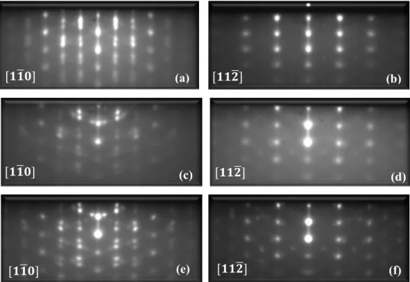
Figure 3 gathers the RHEED images collected after the deposition of the TbFe2 layers on LNZ/Ti (a and b),
LNZ/Mo (c and d) and LNZ/Ti/Mo (e and f). Those are measured along the two main azimuthal directions of LNZ reported above (Figure 1 (a) and (b)).
For these three cases, the TbFe2 RHEED images exhibit spotty streaks with a relatively high diffuse background
that can be related to both disorder and roughness at the surface. One can also notice the presence of extra spots and tilted streaks that do not seem to belong to a single diffraction pattern. They could be linked to the presence of multiple domains but also to the occurrence of crystalline facets at the surface, as it has already be reported for the growth of DyFe2 on Al2O3/Nb [OST05].
Despite slight differences between these layers on different templates, for each case, two distinct diffraction patterns are observed, separated by 30° and reproduced every 60°. The in-plane symmetry together with the relative inter-streaks distances (a ratio of 1.73) enable us to conclude to the occurrence of a (111) growth plane:
(111) TbFe // Ti (0001) // LN (0001) (111) TbFe // Mo (110) // LN (0001) (111) TbFe // Mo (110) // Ti (0001) // LN (0001)
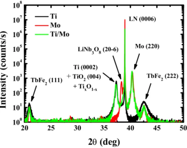
X-ray scattering specular scans (Figure 5) confirm the (111) TbFe2 growth for each case. Note that the FWHM of
the rocking curve (not reported here) across the TbFe2 (111) Bragg peak is 1.5° on LNZ/Ti and 2° on LNZ/Mo
and LNZ/Ti/Mo. The coherence lengths are approximatively 20 nm on LNZ/Mo and LNZ/Ti/Mo but is reduced to 11 nm on LNZ/Ti, despite the single domain character of this buffer compared to others. The TbFe2 structural
characteristics are thus slightly degraded on LNZ/Ti but rather similar on the Mo or double Ti/Mo templates. From the specular Bragg peak position, one can also deduce that the TbFe2 films are under tensile strain (approx.
+0.16%) on the three templates. Because of the large thickness of the deposited films and of the relatively complex OR with significant lattice mismatches [POL18], the strains likely arise from the different thermal expansion coefficients of the deposited layers and the substrate, as it has been previously reported [WAN96, MOU99]. A simple model using the elastic internal energy, as expressed in [POL18], confirms the expected tensile strains. One can eventually mention a supplementary peak on the left of the LN diffraction peak, which can be attributed to LiNb3O8. This compound may form during the heating in UHV yielding the depletion in Lithium and Oxygen
superimposed with Ti. In these latter, a Ti oxidation also likely occurs during Mo or TbFe2 depositions, which
gives rise to a mix of Ti (0002)/Anatase TiO2 (004) and possibly TixO1-x.
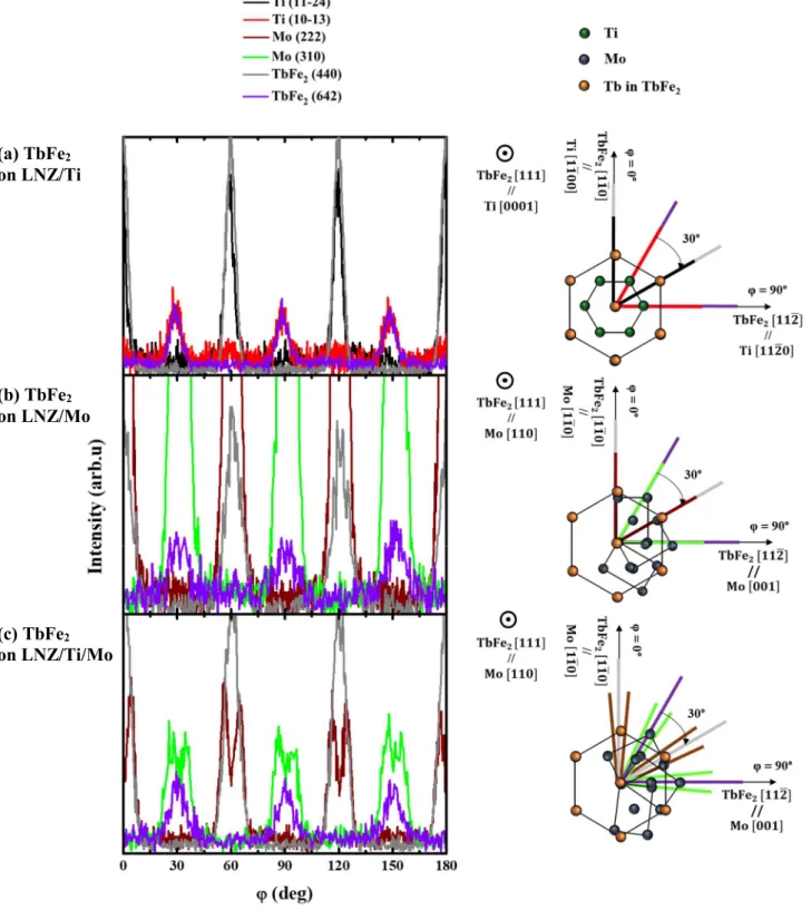
In-plane OR have been clarified by φ scans of various AR scattering, as presented in Figure 4 ((a) for LNZ/Ti/TbFe2, (b) for LNZ/Mo/TbFe2 and (c) for LNZ/Ti/Mo/TbFe2).
In each case, φ scans for the TbFe2 ARs show diffraction conditions every 60°, while 120° are expected from the
[111] orientated Laves phase structure. They reveal the presence of two variants rotated by 60° around the [111] growth direction. Both variants however originate from the same in-plane OR with respect to the underlying layer. On LNZ/Ti, in-plane epitaxial relationships are:
TbFe [112] // Ti [1120] // LN [1100] TbFe [110] // Ti [1100] // LN [1120] On LNZ/Mo, in-plane epitaxial relationships are:
TbFe [112] /⁄ Mo [001] // LN [1100] TbFe [110] /⁄ Mo [110] // LN [1120]
As in the case of (110) Mo on (0001) LN, this OR is the so-called R30 OR, with a 1 TbFe2 : 1 Mo coincidence
between atomic rows perpendicular to Mo [110], and a 1 TbFe2 : 3 Mo coincidence between atomic rows
perpendicular to Mo [001]. As shown previously, the optimal ratio = / to account for this orientation is 0.5. The experimental ratio in the case of Mo and TbFe2 is 0.52, which explains this preferred relative orientation,
also consistent with previous results reported for the (111) TbFe2 growth on (110) Mo on sapphire substrates
[HUT98a]. Note that, for symmetry reasons, the presence of three Mo domains doesn’t prevent from the growth of a unique in plane orientation for TbFe2 (111) planes.
When TbFe2 is deposited on LNZ/Ti/Mo, it appears from the φ scans that in-plane TbFe2 < 112 > directions are
in between the close Mo < 001 > directions. Similarly, in-plane TbFe2 < 110 > directions are in between the
close Mo < 110 > directions. This peculiar OR most likely results from the same R30-OR described above for (111) TbFe2 on (110) Mo. In the present case where six KS (110) Mo domains are present, their relative orientation
should give rise to two (111) TbFe2 domains, rotated by 10.52 ° [HEL98]. These cannot be separated in the
measured φ scans that rather suggest the merge into a single median domain with large in-plane dispersion. One can eventually notice that the in-plane dispersion of the TbFe2 directions appear namely smaller in the case of
the single Ti buffer layer than for the other templates. This is most likely related to the single domain nature of the underlying Ti layer compared to the presence of three or six Mo domains.
IV. Magnetic properties of the TbFe
2magnetic layer
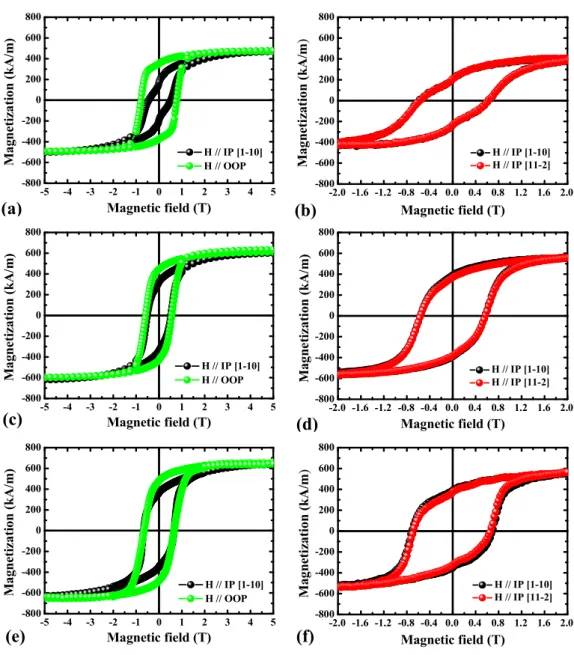
Magnetic hysteresis loops have been measured at room temperature with magnetic fields applied In the Plane (IP) along different directions, and Out Of the Plane (OOP) of the TbFe2 layers deposited on the various buffer layers.
Figure 6 (a, c and e) presents the comparison between IP (H // [110] TbFe2 // LN [1120]) and OOP loops, and
Figure 6 (b, d and f) presents the IP measurements along two orthogonal directions. No demagnetizing field corrections were performed for OOP loops in order to show the magnetic field actually needed to magnetically saturate the film. The diamagnetic contributions from the sample holder and substrate have been subtracted. A first observation is that, in any case, the saturation magnetization is significantly smaller than the value expected from the bulk (800 kA.m-1). This is a sign of limited quality of the films and could be attributed to different factors:
chemical contamination by neighbor elements and/or elements diffusing from the substrate, oxidation…The Ti buffer layer alone may constitute an inefficient chemical barrier and lead to a small saturation magnetization, likely related to the reduced coherence length. Mo and Ti/Mo buffers on which the TbFe2 structural properties are similar
also lead to close saturation magnetization, without a clear improvement brought by the supplementary Ti layer. Further investigations would require detailed chemical analysis and surface analysis that have not been performed during this work.
The comparison of IP (black) and OOP (green) measurements shows that TbFe2 films deposited on Ti, Mo and
Ti/Mo exhibit a tendency to perpendicular magnetization (larger remanent magnetization, less rounded shape of the hysteresis loop), especially in the case of the single Ti buffer. This OOP magnetic anisotropy is consistent with the expected influence of the magnetoelastic contribution when taking the measured lattice strain into account. In fact, for [111] growth direction, a perpendicular tensile strain favors an OOP magnetization, while a perpendicular compressive strain favors an IP magnetization. It is also consistent with previously reported results for REFe2 and
REAl2 films deposited on various substrates with either smaller or larger thermal expansion coefficients, thus
single Ti buffer promotes a stronger OOP anisotropy, likely connected to the smaller magnetization value, i.e. the smaller contribution of the demagnetizing field.
The comparison of IP measurements with the field applied along different directions shows that the IP magnetic behavior is isotropic for all TbFe2 films, whatever the buffer layers. In the case of the current [111] growth
direction, the presence of two variants leads to six < 111 > directions (easy direction in the bulk compound), rotated by 60° in azimuthal angle from each other, and tilted by 20° from the sample plane. The angle between any in-plane direction and an out-of-plane < 111 > direction is therefore in the [20°-35°] range (20° for < 112 > directions and 35° for < 110 > directions). Given the structural dispersion, this difference is obviously not large enough to induce an in-plane magnetic anisotropy.
V. Conclusion
The epitaxial growth of the highly magnetostrictive TbFe2 compound on piezoelectric LN Z-cut substrates has
been thoroughly studied using different buffer layers: single Ti or Mo layers and double Ti/Mo template. The epitaxial growth along the [111] direction (with two variants rotated by 60°) has been interestingly achieved on these various templates, with a reasonable structural quality as evidenced by the X-ray scattering experiments. This could be obtained on the single domain (0001) Ti, as well as on multi-domains (110) Mo (three domains on LN, six domains on LN/Ti). Surprisingly, the final orientation relationships between the 50 nm thick (111) TbFe2
and the (0001) LN surface ([112] TbFe2 // [1100] LN and [110] TbFe2 // [1120] LN) don’t depend on the
intermediate buffer layer, or on the presence of domains.
The TbFe2 magnetization could reach 80% of the bulk value for deposition on Mo or Ti/Mo but is smaller on the
single Ti buffer. Compared to the Mo buffer, the Ti/Mo double template doesn’t really benefit here to the TbFe2
characteristics, neither structural nor magnetic, and a simple single Mo buffer layer is therefore a better alternative that could be more easily transferred to other LN orientations with stronger piezoelectric response [POL19]. Our results here differ from the previous work by Huth [HUT99] who concluded to an optimal TbFe2 layer when
deposited on the double template; the authors however don’t mention the observation of multiple Mo domains on (110)Ti.
These results constitute an important advance towards the development of efficient hybrid structures for magnetic field sensing or the electric control of magnetization. A next step will consist in determining the minimal buffer thickness that still enables satisfactory structural and magnetic TbFe2 properties, in order to benefit from the best
mechanical coupling between magnetostrictive and piezoelectric compounds and to reduce the time spent at high temperature during deposition, which appears detrimental to the chemistry and structure of the LN interface region.
Appendix
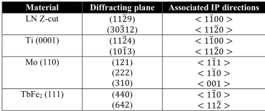
The measurement of selected asymmetrical Bragg reflections while rotating the sample around its surface normal (φ angle) permits to analyze the in-plane and relative orientations of various materials (LN, Ti, Mo and TbFe2).
The Table 1 gathers for the different materials the measured asymmetrical reflections and the corresponding in-plane directions that can be thus determined.
Material Diffracting plane Associated IP directions
LN Z-cut (1129) (30312) < 1100 > < 1120 > Ti (0001) (1124) (1013) < 1100 > < 1120 > Mo (110) (121) (222) (310) < 111 > < 110 > < 001 > TbFe2 (111) (440) (642) < 110 > < 112 >
Table 1. Asymmetrical Bragg reflections measured with φ scans for the different materials and in-plane directions that can be deduced.
Acknowledgments
Experiments were carried out on IJL Project TUBE-Davm equipments funded by FEDER (EU), French PIA project “Lorraine Université d’Excellence” (ANR-15-IDEX-04-LUE), Region Grand Est, Metropole Grand Nancy and ICEEL.
References
[ATU10] J. Atulasimha and S. Bandyopadhyay, Benett clocking of nanomagnetic logic using multiferroic single-domain nanomagnets, Appl. Phys. Lett. 97, 173105, (2010).
[AVI08] A. Avisou, C. Dufour and K. Dumesnil, Control of magnetic anisotropy in (111) SmAl2 films, J. Appl.
Phys. 103, 07E135, (2008).
[CLA80] A. E. Clark, Magnetostrictive RFe2 intermetallic compounds, Chap. 15, in Handbook on the physics and
chemistry of rare earths, North Holland Publishing Company, (1980).
[DUQ19] J. Y. Duquesne, P. Rovillain, C. Hepburn, M. Eddrief, P. Atkinson, A. Anane, R. Ranchal and M. Marangolo, Surface-Acoustic-Wave Induced Ferromagnetic Resonance in Fe Thin Films and Magnetic Field Sensing , Phys. Rev. App. 12 024042, (2019).
[ELH16] M. Elhosni, O. Elmazria, S. Petit-Watelot, L. Bouvot, S. Zhgoon, A. Talbi, M. Hehn, K. Ait Aissa, S. Hage-Ali, D. Lacour, F. Sarry and O. Boumatar, Magnetic field SAW sensors based on magnetostrictive-piezoelectric layered structures: FEM modeling and experimental validation, Sensors and Actuators A: Physical. 240, 41-49, (2016).
[HEL98] 0. Hellwig, K. Theis-Briihl, G. Wilhelmi, A. Stierle and H. Zabel, Growth of fcc (111) on bcc (110): new type of epitaxial transition observed for Pd on Cr, Surface Science. 398, 379-385, (1998).
[HOM87] H. Homma, K. Y. Yang and I. K. Schuller, Role of lattice matching in epitaxy: Novel Ce Phase and new fcc-bcc epitaxial relationship, Phys. Rev. B. 36, 18 (1987).
[HUT98a] M. Huth and C. P. Flynn, Magnetism and microstructure in epitaxial TbFe2 (111) thin films, Phys. Rev.
B. 58, 17, (1998).
[HUT98b] M. Huth and C. P. Flynn, Effect of heteroepitaxial strain on Laves phases TbFe2 and DyFe2, J. Appl.
Phys. 83, 7261, (1998).
[HUT99] M. Huth and C. P. Flynn, Strain-induced perpendicular magnetization in TbFe2 (111) thin films on
LiNbO3, J. Mag. and Magn. Mat. 204, 204-208, (1999).
[KWO86] J. Kwo, M. Hong and S. Nakahara, Growth of rare-earth single crystals by molecular beam epitaxy: the epitaxial relationship between hcp rare earth and bcc niobium, Appl. Phys. Lett. 49, 319, (1986).
[MIS17] H. Mishra, V. Polewczyk, M. Hehn, M. Moutaouekkil, C. Floer, K. Dumesnil, D. Lacour, S. Petit-Watelot, H. Mjahed, S. Hage-Ali, O. Elmazria, N. Tiercelin, Y. Dusch, A. Talbi, O. Bou Matar, Control of the magnetic response in magnetic field SAW sensors, IEEE Sensors. 8233971, (2017).
[MOU99] A. Mougin, C. Dufour, K. Dumesnil, N. Maloufi and Ph. Mangin, Strain in single-crystal RFe2 (110)
thin films (R = Y, Sm, Gd, Tb, Dy0.7Tb0.3, Dy, Er, Lu), Phys. Rev. B. 59, 8, (1999).
[MOU00] A. Mougin, C. Dufour, K. Dumesnil and Ph. Mangin, Strain-induced magnetic anisotropy in single-crystal RFe2 (110) thin films (R = Dy, Er, Tb, Dy0.7Tb0.3, Sm, Y), Phys. Rev. B. 62, 14, (2000).
[NAM05] G. Namkoong, K. K. Lee, S. M. Madison, W. Henderson, S. E. Ralph and W. A. Doolittle, III-nitride integration on ferroelectric materials of lithium Niobate by molecular beam epitaxy, Appl. Phys. Lett. 87, 171107, (2005).
[ODE96] V. Oderno, C. Dufour, D. Dumesnil, Ph. Mangin and G. Marchal, Epitaxial growth of (110) DyFe2,
TbFe2 and Dy0,7Tb0,3Fe2 thin films by molecular beam epitaxy, Journal of Crystal Growth. 165, 175-178, (1996).
[OST05] J. Otser, L. Wiehl, H. Adrian and M. Huth, Magnetic and magnetoelastic properties of epitaxial (211)-oriented RFe2 (R=Tb or Dy) thin films, J. Mag. and Magn. Mat. 292, 164-177, (2005).
[PER09] N. A. Pertsev, H. Kohlstedt and B. Dkhil, Strong enhancement of the direct magnetoelectric effect in strained ferroelectric-ferromagnetic thin-film heterostructures, Phys. Rev. B. 80, 054102, (2009).
[POL17] V. Polewczyk, K. Dumesnil, D. Lacour, M. Moutaouekkil, H. Mjahed, N. Tiercelin, S. Petit Watelot, Y. Dusch, S. Hage-Ali, O. Elmazria, F. Montaigne, A. Talbi, O. Bou Matarand M. Hehn, Unipolar and bipolar high-magnetic field sensors based on surface acoustic wave resonators, Phys. Rev. App. 8, 024001, (2017).
[POL18] V. Polewczyk, Growth of hybrid piezoelectric/magnetostrictive systems for magnetic devices based on surface acoustic wave resonators, PhD dissertation, Université de Lorraine, Nancy, (2018).
[POL19] V. Polewczyk, M. Hehn, A. Hillion, S. Robert, P. Boulet and K. Dumesnil, Epitaxial growth of magnetostrictive TbFe2 films on LiNbO3, J. of Phys: Cond. Matt. 31, 405801, (2019).
[RYU02] J. Ryu, S. Priya, K. Uchino and H. E. Kim, Magnetoelectric effect in composites of magnetostrictive and piezoelectric materials, J. Electroceram. 8, 107-119, (2002).
[THE16] L. Thevenard, I. S. Camara, S. Majrab, M. Bernard, P. Rovillain, A. Lemaitre C. Gourdon and J. Y. Duquesne, Precessional magnetization switching by a surface acoustic wave, Phys. Rev. B. 93, 134430, (2016). [WAN96] C. T. Wang, B. M. Clemens and R. L. White, Effects of substrate on the magnetic properties of epitaxial TbFe2 (111) films, IEEE. Trans. Magn. 32, 4752, (1996).
[WEI11] M. Weiler, L. Dreher, C. Heeg, H. Huebl, R. Gross, M. S. Brandt and S. T. B. Goennenwein, Elastically driven ferromagnetic resonance in Nickel thin films, Phys. Rev. Lett. 106, 117601, (2011).
Figure 1. RHEED patterns collected for LN Z-cut at 500 °C along two azimuths rotated by 90° (a and b),for 50 nm thick Ti deposited at 100 °C along the same azimuthal directions (c and d), for 50 nm thick Mo (e and f) and
for Ti/Mo (g and h) of 50 nm thick each deposited at 450 °C along two azimuths rotated by 30°.
[
]
(c)
[
]
(d)
LNZ/Ti
[
]ext
[
]int
[
]int
[
]ext
LNZ/Mo
(f)
(e)
[
]ext
[
]int
[
]int
[
]ext
(g)
(h)
LNZ/Ti/Mo
[
]
[
]
(a)
(b)
LNZ
Figure 2. φ scans for asymmetrical reflections measured for LNZ/Ti (a), LNZ/Mo (b) and LNZ/Ti/Mo (c). The sketches on the right are superimpositions of the corresponding planes deduced from the φ scans. For the
sake of clarity, only three of the six Mo domains are presented on the bottom sketch
(a) LNZ/Ti
(b) LNZ/Mo
Figure 3. RHEED patterns collected at 650 °C along two azimuths rotated by 90° for 50 nm thick TbFe2
deposited on LNZ/Ti (a and b), LNZ/Mo (c and d) and LNZ/Ti/Mo (e and f).
[
]
(a)
[
]
(b)
TbFe
2on LNZ/Ti
[
]
(c)
[
]
(d)
TbFe
2on LNZ/Mo
[
]
(e)
[
]
(f)
TbFe
2on LNZ/Ti/Mo
Figure 4. φ scans for asymmetrical reflections measured for (a) LNZ/Ti/TbFe2, (b) LNZ/Mo/TbFe2 and (c) LNZ/Ti/Mo/TbFe2
The sketches on the right are superimpositions of the corresponding planes deduced from the φ scans. For the sake of clarity, only three of the six Mo domains are presented on the bottom sketch
(a) TbFe
2on LNZ/Ti
(b) TbFe
2on LNZ/Mo
(c) TbFe
2on LNZ/Ti/Mo
20 25 30 35 40 45 50 100 101 102 103 104 105 106 107 108 + TiO2 (004) + TixO1-x LN (0006) Ti Mo Ti/Mo In te ns it y (c ou nt s/ s) 2 (deg) TbFe2 (111) TbFe2 (222) Mo (220) Ti (0002) LiNb3O8 (20-6)
Figure 5. X-ray scattering θ/2θ specular scans measured for LNZ/Ti/TbFe2 (black), LNZ/Mo/TbFe2 (red) and
-5 -4 -3 -2 -1 0 1 2 3 4 5 -800 -600 -400 -200 0 200 400 600 800 M ag n et iz at io n ( k A /m ) Magnetic field (T) H // IP [1-10] H // OOP -2.0 -1.6 -1.2 -0.8 -0.4 0.0 0.4 0.8 1.2 1.6 2.0 -800 -600 -400 -200 0 200 400 600 800 H // IP [1-10] H // IP [11-2] M ag ne ti za ti on ( k A /m ) Magnetic field (T) -5 -4 -3 -2 -1 0 1 2 3 4 5 -800 -600 -400 -200 0 200 400 600 800 M ag n et iz at io n ( k A /m ) Magnetic field (T) H // IP [1-10] H // OOP -2.0 -1.6 -1.2 -0.8 -0.4 0.0 0.4 0.8 1.2 1.6 2.0 -800 -600 -400 -200 0 200 400 600 800 M ag ne ti za ti on ( k A /m ) Magnetic field (T) H // IP [1-10] H // IP [11-2] -5 -4 -3 -2 -1 0 1 2 3 4 5 -800 -600 -400 -200 0 200 400 600 800 M ag n et iz at io n ( k A /m ) Magnetic field (T) H // IP [1-10] H // OOP -2.0 -1.6 -1.2 -0.8 -0.4 0.0 0.4 0.8 1.2 1.6 2.0 -800 -600 -400 -200 0 200 400 600 800 M ag ne ti za ti on ( k A /m ) Magnetic field (T) H // IP [1-10] H // IP [11-2]
Figure 6. Hysteresis loops measured at room temperature with the magnetic field applied IP along two orthogonal directions (black and red) and OOP (green) for 50 nm thick TbFe2 layers deposited on different
templates (single buffer layers (Ti (a and b) and Mo (c and d)) and double buffer layers (Ti/Mo (e and f)).