HAL Id: hal-02481867
https://hal.archives-ouvertes.fr/hal-02481867
Submitted on 17 Feb 2020
HAL is a multi-disciplinary open access
archive for the deposit and dissemination of
sci-entific research documents, whether they are
pub-lished or not. The documents may come from
teaching and research institutions in France or
abroad, or from public or private research centers.
L’archive ouverte pluridisciplinaire HAL, est
destinée au dépôt et à la diffusion de documents
scientifiques de niveau recherche, publiés ou non,
émanant des établissements d’enseignement et de
recherche français ou étrangers, des laboratoires
publics ou privés.
Photoacoustic guidance of high intensity focused
ultrasound with selective optical contrasts and
time-reversal
Arik Funke, Jean-François Aubry, Mathias Fink, Albert-Claude Boccara,
Emmanuel Bossy
To cite this version:
Arik Funke, Jean-François Aubry, Mathias Fink, Albert-Claude Boccara, Emmanuel Bossy.
Photoa-coustic guidance of high intensity focused ultrasound with selective optical contrasts and time-reversal.
Applied Physics Letters, American Institute of Physics, 2009, 94 (5), pp.054102. �10.1063/1.3077018�.
�hal-02481867�
Appl. Phys. Lett. 94, 054102 (2009); https://doi.org/10.1063/1.3077018 94, 054102 © 2009 American Institute of Physics.
Photoacoustic guidance of high intensity
focused ultrasound with selective optical
contrasts and time-reversal
Cite as: Appl. Phys. Lett. 94, 054102 (2009); https://doi.org/10.1063/1.3077018
Submitted: 14 December 2008 . Accepted: 08 January 2009 . Published Online: 03 February 2009 Arik R. Funke, Jean-François Aubry, Mathias Fink, Albert-Claude Boccara, and Emmanuel Bossy
ARTICLES YOU MAY BE INTERESTED IN
Photoacoustic imaging in biomedicine
Review of Scientific Instruments 77, 041101 (2006); https://doi.org/10.1063/1.2195024 Time reversal of photoacoustic waves
Applied Physics Letters 89, 184108 (2006); https://doi.org/10.1063/1.2382732 Iterative reconstruction algorithm for optoacoustic imaging
The Journal of the Acoustical Society of America 112, 1536 (2002); https:// doi.org/10.1121/1.1501898
Photoacoustic guidance of high intensity focused ultrasound with selective
optical contrasts and time-reversal
Arik R. Funke, Jean-François Aubry, Mathias Fink, Albert-Claude Boccara, and Emmanuel Bossya兲
Institut Langevin, ESPCI ParisTech, CNRS UMR 7587, 10 rue Vauquelin, 75231 Paris Cedex 05, France
共Received 14 December 2008; accepted 8 January 2009; published online 3 February 2009兲 The authors present a method of focusing high intensity ultrasound by time-reversing the photoacoustic response of an optically selective target in a nonselective background. The target’s photoacoustic response was isolated from the background by subtracting the photoacoustic waveforms obtained at different optical wavelengths and convolved with a continuous signal. It was found that the focus produced was comparable in quality to that obtained by delay-law beam-forming. The method holds the promise of allowing precise targeting of high intensity focused ultrasound on nonechogenic targets, in moving environments, independently of the presence of aberrating layers. © 2009 American Institute of Physics.关DOI:10.1063/1.3077018兴
High intensity focused ultrasound 共HIFU兲 allows the noninvasive treatment of tumors by raising the tissue tem-perature locally to induce apoptosis and thermal necrosis without damage to surrounding tissues.1,2However, the abil-ity to focus ultrasound is essential to ensure sufficiently lo-calized energy deposition and thus limit the thermal necrosis to the target region. This requirement becomes a limiting factor to the application of the method where the target re-gion lies behind an ultrasonically aberrating layer such as an irregular layer of fat tissue, intracostally, or intracranially. Other challenges arise from the motion of the target, e.g., due to respiration, or from nonechogenic targets leading to un-certainty in the position of the target.
One approach that has been shown to allow compensat-ing very effectively for aberration effects is time reversal, or in the continuous wave case, phase-conjugation methods. Given that the wave equation exhibits time-reversal invari-ance, if a point source at the desired focus can be generated and its signal be acquired after traversing the aberrating layer and reemitted temporally reversed, the reemitted signal will reconverge at the position of the point source.3,4
One essential requirement for time-reversal methods is the existence of a point source at the desired focus. Depend-ing on the application, various methods have been developed to generate such a point source. An early, and to date still the most effective, approach, was to implant a needle hydrophone intracranially to serve as a point source via reciprocity.5,6 While this approach can be minimally inva-sive, a noninvasive technique would be preferable especially in the case of the brain. Alternatives are the generation of a cavitation bubble7 or the simulation of a point source in a virtual model of the acoustic medium that was acquired by x-ray computed tomography.8–10 The first alternative may suffer from the uncertainty in the axial position of the gen-erated bubble. The second one is limited by the duration of the required computations and the need for the alignment between the virtual model and real world with millimetric precision. Various methods have been developed for the challenge of motion compensation, e.g., based on cross
cor-relation of the acoustic speckle pattern.10,11 For targeting of nonechogenic targets, multimode systems with a shared co-ordinate system are currently necessary for precise treatment, e.g., HIFU under magnetic resonance imaging guidance.12
In this letter, a method of HIFU guidance is proposed. It potentially offers convenient solutions to the problems of aberration correction, motion compensation, and non-echogenic targets via photoacoustic generation in the target. Photoacoustic generation refers to the generation of acoustic waves by an optical absorber that undergoes ther-moelastic expansion upon absorption of a light pulse. The resulting photoacoustic pressure field p is given by
⌬p − 1 cs 2 2p t2 = −  cp H t ,
where H共r៝, t兲=a共r៝兲共r៝, t兲 and where ⌬ is the Laplacian, H is the density of absorbed optical energy per unit time, cs is the adiabatic sound speed,  is the isobaric thermal expan-sion coefficient, cp is the specific heat,a is the optical ab-sorption coefficient, and is the fluence rate. In an earlier work, we showed that the photoacoustic signal from a black sphere suspended in an optically scattering medium can be used with time-reversal methods to correct for aberrating layers.13 However, only a single optical absorber was present. This is in stark contrast to a biological environment where numerous different chromophores and structures, such as, for example, blood vessels, may produce strong photoa-coustic signals compared to the target of interest.
Photoacoustic spectroscopy has been used with endog-enous contrasts to access functional tissue parameters.14,15In this work it is proposed to use photoacoustic signals for the guidance of HIFU treatment by attaching an exogenous op-tically selective contrast agent to the target region and using the difference in the photoacoustic waveforms generated at different optical wavelengths to extract targeting informa-tion. The proposed method holds the promise of allowing to learn to focus on a target region beyond aberrating layers and of allowing to compensate for target motion, thanks to the rapidity of the method; time-reversal correction is physically limited by the total time of flight 共typically 67 s for a target located 5 cm in the tissue兲. Given that the focusing
a兲Author to whom correspondence should be addressed. Electronic mail: emmanuel.bossy@espci.fr.
APPLIED PHYSICS LETTERS 94, 054102共2009兲
process is based fundamentally on optical absorption, the targets need not be echogenic. In the following a proof-of-concept is presented with tubes filled with ink used as optical absorbing structures, embedded in a phantom that mimics specifically the optical properties of biological tissue.
The experimental setup is shown in Fig. 1. The tubes were made of optically transparent PVC, 50 mm in height with an internal diameter and wall thickness of 0.8 mm each. They were arranged vertically and quasirandomly in a 50 mm共depth兲⫻80 mm共transverse兲 area with a spacing of typically 17 mm. All but one of these tubes were filled with a solution of black India ink with a= 8.0 cm−1 at 1 = 672 nm and a= 7.3 cm−1 at
2= 730 nm. One of the tubes, located roughly at the center, was filled with a solution of green India ink with a= 8.0 cm−1 at
1 and a = 0.2 cm−1 at 2. The tubes filled with black ink simulate nonselective optical absorption, e.g., from blood vessels. The tube filled with green ink serves as optically selective target. The set of tubes was placed in an optically transparent aquarium filled with 5.62 l of de-ionized and degassed water in which 450 ml of 10% intralipid was diluted. The resulting solution has a reduced scattering coefficient comparable to that of biological tissue, s
⬘
= 8.9 cm−1 at 1 and s
⬘
= 8.1 cm−1at2.16The tubes are arranged such that the tube filled with green ink was roughly 60 mm from the aquarium wall and 60 mm from the transducer surface. This tissue-mimicking phantom was then illuminated through the aquarium wall with 5 ns light pulses at 1 and 2 with an energy of 100 mJ in a beam with a diameter of approxi-mately 5 mm with a repetition rate of 10 Hz. To generate the light a Surelite OPO Plus driven by a Surelite II-10 共Con-tinuum, CA兲 was used.The generated photoacoustic waveforms were acquired with a commercial 64-element linear imaging probe from Vermon, France with 1.5 MHz nominal central frequency, a 13⫻45 mm2aperture, and 60 mm prefocusing in elevation. The probe was connected to a time-reversal system 共Open System, Lecoeur Electronique, France兲 with 64 indepen-dently programmable channels with a sampling frequency of 80 MHz triggered by the laser. The data were transferred and then processed on a computer.
At this stage, neither the ultrasonic probe nor the time-reversal electronics used in this experiment could sustain the energies necessary for HIFU. Thus to test the ability to guide “HIFU mode” signals, 45 s sinusoidal signals were emit-ted with the maximum available energy for our system on all channels. To test the ability to guide HIFU mode signals, the
tubes were removed from the aquarium and a hydrophone 共HGL-400, Onda, CA兲 was introduced. With the aid of ultra-sonic imaging the hydrophone was positioned at the location of the target tube relative to the ultrasonic probe and scanned transversally to the ultrasonic probe, while the ultrasonic probe emitted the time-reversed signals.
Due to the limits on the permissible energy density of the illumination of biological tissue and the strong scattering the light experiences, the energy available for absorption by optical contrasts embedded at several centimeters in depth is scarce. To increase the SNR of the data, the acquired pho-toacoustic signals were averaged over 86 acquisitions, and the result was filtered with the bandwidth of the transducer. Moreover, the fluence rate decreases with increasing dis-tance from the point of light injection. In consequence, as the amplitude of photoacoustic signals is proportional to the ab-sorbed energy for short pulses, identical optical absorbers at different depths produce photoacoustic signals of different amplitudes. To compensate for the unknown attenuation of the fluence rate, a compensation function was calculated us-ing regression on the amplitude of the photoacoustic wave-forms as a function of depth; assuming that light injection can be considered as a point source in the scattering medium, the fluence rate decays as r−1exp共−
effr兲, where r is the dis-tance from the point of light injection and effan effective light attenuation coefficient.
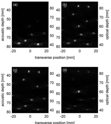
For our data analysis we used the maximum value of each acquisition line, thereby treating the distance coordinate r as equivalent to the depth from the aquarium wall. The effect of the attenuation on the photoacoustic waveforms can then be compensated for by normalizing with the result of the regression. Figure 2 shows beam-formed photoacoustic images obtained from the photoacoustic waveforms at differ-ent stages of the signals processing. Figure2共a兲is based on the photoacoustic waveforms obtained at 1 共with back-ground and target兲 after averaging and filtering, while Fig.
2共b兲is based on the photoacoustic waveforms obtained at1 after additionally applying the compensation function. In this experiment eff= 0.7 cm−1was found for both 1 and2.
The attenuation-compensated photoacoustic waveforms obtained at the two different optical wavelengths were then subtracted. Characteristics that were identical at both wave-lengths, i.e., photoacoustic signals from optically nonselec-tive absorbers, cancelled and only the differences remained, i.e., the signals from the optically selective target. This result shall be referred to in the following as “difference wave-forms.” Comparing Fig. 2共b兲 based on waveforms obtained at 1 共with background and target兲 and Fig. 2共c兲based on waveforms obtained2共with background but without target兲, it is clear that in Fig.2共b兲the target is missing at the center of the image. Figure 2共d兲 shows the result based on the dif-ference waveforms. The residual signal remaining at the po-sitions of the nonselective absorbers can be explained by the fact that the PVC tubes used to contain the ink solutions are not entirely transparent but absorb differently at1and2.
To construct the signal for the verification of the ability to focus HIFU mode ultrasound, a sinusoidal signal of 45 s duration was created for all emission channels at the fre-quency that corresponds to the maximum of the difference waveforms, f = 1.16 MHz. The emission signal was defined by convolving either with the time-reversed photoacoustic waveforms obtained at 1 or with the time-reversed differ-FIG. 1. Experimental setup. CO denotes collimation optics.
ence waveforms. Focusing was verified by scanning a hydro-phone in the plane of the target normal to the acoustic axis. The effectiveness of using an optically selective absorber embedded in an environment with multiple nonselective ab-sorbers for the targeting of ultrasound is illustrated in Fig.3.
The figure plots the acoustic pressure amplitude measured with a hydrophone in the plane of the target. The position of the optically selective target corresponds to 0 mm. To serve as a basis for comparison, the fine line corresponds to the focus obtained by beam forming the emitted signal with a conventional delay law for homogeneous media. In Fig.3共a兲 the bold line illustrates the pressure amplitude distribution obtained by convolving the sinusoidal signal with the time-reversed photoacoustic waveforms obtained at1. They con-tain the waveforms from the selective and nonselective ab-sorbers and consequently produce foci on the selective and the various nonselective absorbers, spreading the acoustic energy over the entire phantom. In Fig. 3共b兲 the bold line plots the focus produced by convolving the sinusoidal signal with the time-reversed difference waveforms. It contains es-sentially the isolated photoacoustic waveforms of the opti-cally selective target. The figure clearly shows that the full width half maximum of the focus obtained from conven-tional delay-law beam-forming and from convolving with the photoacoustic waveform is quasi identical.
In conclusion, a method for guiding HIFU mode ultra-sound with a selective-optical contrast agent and time-reversal was proposed and its feasibility demonstrated with a tissue phantom and a commercial imaging probe. This method holds the promise of allowing overcoming three sig-nificant challenges in HIFU treatment: aberration correction, movement compensation, and targeting of nonechogenic tar-gets. An important remaining challenge is the detection the photoacoustic signals with sufficient SNR with a transducer that can withstand the sustained powers necessary for HIFU treatment.
The authors gratefully acknowledge the support of the Centre National de la Recherche Scientifique and the Agence Nationale de la Recherche 共Grant No. JC07-195015兲.
1F. Wu, Z. B. Wang, W. Z. Chen, J. Z. Zou, J. Bai, H. Zhu, K. Q. Li, F. L. Xie, C. B. Jin, H. B. Su, and G. W. Gao,Ultrasound Med. Biol. 30, 245 共2004兲.
2R. O. Illing, J. E. Kennedy, F. Wu, G. R. ter Haar, A. S. Protheroe, P. J. Friend, F. V. Gleeson, D. W. Cranston, R. R. Phillips, and M. R. Middle-ton,Br. J. Cancer 93, 890共2005兲.
3M. Fink,IEEE Trans. Ultrason. Ferroelectr. Freq. Control 39, 555共1992兲. 4M. Fink and C. Prada,Inverse Probl. 17, R1共2001兲.
5M. Tanter, J. L. Thomas, and M. Fink,J. Acoust. Soc. Am. 103, 2403 共1998兲.
6M. Pernot, J. F. Aubry, M. Tanter, A. L. Boch, F. Marquet, M. Kujas, D. Seilhean, and M. Fink,J. Neurosurg. 106, 1061共2007兲.
7M. Pernot, G. Montaldo, M. Tanter, and M. Fink,Appl. Phys. Lett. 88, 034102共2006兲.
8J. F. Aubry, M. Tanter, M. Pernot, J. L. Thomas, and M. Fink,J. Acoust.
Soc. Am. 113, 84共2003兲.
9G. T. Clement and K. Hynynen,Phys. Med. Biol. 47, 1219共2002兲. 10M. Tanter, M. Pernot, J. F. Aubry, G. Montaldo, F. Marquet, and M. Fink,
Int. J. Hyperthermia 23, 413共2007兲.
11M. Pernot, M. Tanter, and M. Fink, Ultrasound Med. Biol. 30, 1239 共2004兲.
12C. M. C. Tempany, E. A. Stewart, N. McDannold, B. J. Quade, F. A. Jolesz, and K. Hynynen,Radiology 226, 897共2003兲.
13E. Bossy, K. Daoudi, A. C. Boccara, M. Tanter, J. F. Aubry, G. Montaldo, and M. Fink,Appl. Phys. Lett. 89, 184108共2006兲.
14E. V. Savateeva, A. A. Karabutov, S. V. Solomatin, and A. A. Oraevsky,
Proc. SPIE 4618, 63共2002兲.
15X. D. Wang, X. Y. Xie, G. N. Ku, and L. H. V. Wang,J. Biomed. Opt.11, 024015共2006兲.
16H. J. Vanstaveren, C. J. M. Moes, J. Vanmarle, S. A. Prahl, and M. J. C. Vangemert, Appl. Opt. 30, 4507共1991兲.
FIG. 2. Beam-formed images based on the waveforms at different steps in the signal processing. 共a兲 is based on the waveforms obtained at 1 after averaging and filtering but without depth compensation, the data of共b兲 were additionally compensated for depth,共c兲 is the analog to 共b兲 but for 2, and 共d兲 is based on the difference waveforms: the isolated target is clearly vis-ible. All images are on a linear gray scale and have been normalized to their respective maximum value.
FIG. 3. Hydrophone scans of the focus produced by a beam-formed sinu-soidal signal共fine line兲 and 共a兲 by reemitting a sinusoidal signal focused by use of the phase of the photoacoustic signals obtained at 672 nm共bold line兲, i.e., with target and background, and共b兲 by reemitting a sinusoidal signal focused by use of the phase of the photoacoustic signal from the isolated target共bold line兲.