HAL Id: hal-00836939
https://hal-polytechnique.archives-ouvertes.fr/hal-00836939
Submitted on 5 May 2014
HAL is a multi-disciplinary open access
archive for the deposit and dissemination of
sci-entific research documents, whether they are
pub-lished or not. The documents may come from
teaching and research institutions in France or
abroad, or from public or private research centers.
L’archive ouverte pluridisciplinaire HAL, est
destinée au dépôt et à la diffusion de documents
scientifiques de niveau recherche, publiés ou non,
émanant des établissements d’enseignement et de
recherche français ou étrangers, des laboratoires
publics ou privés.
Picosecond and nanosecond polychromatic pump-probe
studies of bubble growth in carbon-nanotube
suspensions
L. Vivien, D. Riehl, J.-F. Delouis, J. Delaire, François Hache, E. Anglaret
To cite this version:
L. Vivien, D. Riehl, J.-F. Delouis, J. Delaire, François Hache, et al.. Picosecond and
nanosec-ond polychromatic pump-probe studies of bubble growth in carbon-nanotube suspensions.
Jour-nal of the Optical Society of America B, Optical Society of America, 2002, 19 (2), pp.208-214.
�10.1364/JOSAB.19.000208�. �hal-00836939�
Picosecond and nanosecond polychromatic
pump
–
probe studies of bubble
growth in carbon-nanotube suspensions
Laurent Vivien and Didier Riehl
De´le´gation Ge´ne´rale pour l’Armement/Centre Technique d’Arcueil/Department Laser, Optique et Thermo-optique, Arcueil, France
Jean-Franc¸ois Delouis and Jacques A. Delaire
Laboratoire de Photophysique et Photochimie Supramole´culaires et Macromole´culaires, Unite´ Mixte de Recherche, Centre National de la Recherche Scientifique 8531, ENS Cachan, France
Franc¸ois Hache
Ecole Polytechnique, Laboratoire d’Optique et Biosciences, Unite´ Mixte de Recherche, Centre National de la Recherche Scientifique 7645, Palaiseau, France
Eric Anglaret
Universite´ de Montpellier II, Groupe de Dynamique des Phases Condense´es, Unite´ Mixte de Recherche, Centre National de la Recherche Scientifique 5581, Montpellier, France
Received February 27, 2001; revised manuscript received July 25, 2001
Optical limiting in carbon-nanotube suspensions, whose origin lies in a strong nonlinear scattering due to sol-vent vapor bubbles and sublimation of the nanotubes, is investigated in the picosecond and nanosecond re-gimes by polychromatic pump–probe experiments. Samples were pumped either with 532-nm or 1064-nm pulses, and probed from 400 nm to 650 nm. Using a model based on Mie theory, we determine the time evo-lution of the radius and the concentration of the scattering centers for both temporal regimes. We compare the transmission signals for single-wall carbon nanotubes suspended in water and in chloroform and for mul-tiwall carbon nanotubes in water. Several conclusions can be drawn. First, coalescence of gaseous cavities is more effective in water than in chloroform, leading to nonlinear scattering by a smaller number of larger bubbles. Second, in spite of the smaller size of the scattering centers, the limiting efficiency of chloroform suspensions is better than that of water suspensions, due to a larger volume fraction of the gaseous phase. However, the characteristic times for the growth of laser-induced bubbles are too long to allow efficient limiting of subnanosecond laser pulses. © 2002 Optical Society of America
OCIS codes: 190.3970, 190.4400, 190.4870, 290.4020, 290.5850.
1. INTRODUCTION
There is considerable interest in the application of the nonlinear optical properties of materials to optical limiting.1,2 Indeed, the proliferation of laser-based sys-tems is associated with potential harmful effects from these bright, coherent light sources. Nowadays, laser sources (optical parametric oscillators, dye lasers, Raman lasers, ...) are widely used in many applications, not only in the laboratory, but also in many areas of industry and medicine as well as for military applications, and they constitute a potential hazard for eyes and other optical sensors (CCD, thermal camera, ...). It is therefore crucial to protect all sensors against this threat by use of optical limiters. The ideal optical limiter would have high broadband linear transmittance for low input fluences, and the output energy must always remain below the damage threshold of sensors (e.g., camera or human eyes). In addition, this ideal limiter should be efficient from a few picoseconds up to longer pulse durations (from
nanosecond to millisecond) on a broad range of wave-lengths (visible and near infrared). Numerous mecha-nisms have been proposed for optical-limiting applica-tions. Among them, reverse saturable absorption3 has
demonstrated a good efficiency but mainly on relatively narrow spectral bands. Broadband optical limiting and colorimetric neutrality can be obtained by associating sev-eral narrow-band reverse saturable absorption molecules, but such a material generally exhibits a strongly reduced linear transmittance.4 On the other hand, multiphoton
absorbers exhibit an excellent transparency and possess broadband-limiting properties, but only for short laser pulses (t < 10 ns). In contrast, nonlinear-refractive5,6
and nonlinear-scattering7–10 materials, as, for example, carbon-black suspensions,7–9can also provide broadband optical limiting, with better performances for longer laser pulses. Following the discovery of carbon nanotubes by Iijima in 1991,11 many research efforts were focused on this new form of carbon to clarify its attractive physical
properties and in particular nonlinear optical effects. Since 1998, optical-limiting properties of carbon nano-tubes have been the object of numerous investigations, re-vealing that these materials are promising candidates for optical limiting in the visible and near-infrared domains.12–19 They present a broadband transparency
at low input fluences (from 400 to 1100 nm), with excel-lent colorimetric neutrality. The origin of optical limiting in the nanosecond regime is a strong nonlinear scattering induced by the sublimation of the laser-irradiated carbon nanotubes and by the formation of solvent bubbles due to heat transfer from the particles to the surrounding liquid.16–18
In this study, we report picosecond and nanosecond pump–probe results for three kinds of samples: single-wall carbon nanotubes (SWNT) suspended in water and in chloroform and multiwall carbon nanotubes (MWNT) suspended in water, with 532-nm and 1064-nm pump pulses and a polychromatic probe beam that allows deter-mination of the kinetic of bubble formation and coales-cence.
Section 2 presents the synthesis method and the puri-fication procedure of single-wall and multiwall carbon nanotubes. Section 3 reports the results obtained with 30-ps pump pulses, with a comparison between SWNT and MWNT at different pump fluences and probe wave-lengths. In the same section, we also report on nanosec-ond pump–probe experiments. In Section 4 we present a simple calculation that allows estimation of the number and the average radius of the scattering centers respon-sible for the observed drop of probe transmittance. We thus obtain the evolution of the volume fraction of the gas cavities that scatters the probe beam, and we observe coa-lescence and condensation effects.
2. MATERIALS
Carbon nanotubes were synthesized by the electric arc discharge technique.20 An electric arc discharge is
cre-ated between two graphite electrodes under a helium at-mosphere in the presence of a metallic catalyst (Ni and Y with 4.2:1 at.%) for SWNT synthesis and with only pure graphite electrodes for MWNT. As-prepared samples contain impurities such as amorphous carbon, graphite, fullerenes, and residual catalysts. The SWNT samples were purified in a three-step procedure.21 The first step consists of a nitric acid treatment at 100 °C, which par-tially disintegrates the catalyst particles and disen-tangles the complex network of nanotubes, other carbon-ous materials, and catalyst particles. The second one is a tangential filtration that allows separation of the nano-tubes from the other species. Finally, a thermal treat-ment under inert atmosphere eliminates residual cata-lysts. After such a purification procedure, the amount of SWNT is close to 90 vol.% in the samples. SWNT are ob-served to usually self-assemble on a triangular array into crystalline nanobundles of a couple to some tens of tubes.20,22 The diameter of the tubes lies between 1.3
and 1.5 nm,20,23 and their length is about several mi-crometers. For MWNT, amorphous carbon and fullerenes were eliminated by a thermal treatment at 600 °C. The amount of MWNT is close to 80 vol.%, and
their external diameter ranges from 2 to 20 nm depending on the number of layers. SWNT were dispersed in chlo-roform without surfactant and in water with surfactant (triton X100). MWNT were only dispersed in water/ surfactant. For pump–probe experiments, we studied our suspensions in 1-mm-thick cells, coupled with a circu-lation system. The linear transmittances of the colorless samples were larger than 80% from 400 to 1100 nm, and all samples were adjusted at the same linear transmit-tance.
3. PUMP
–
PROBE EXPERIMENTS
A. Picosecond Studies
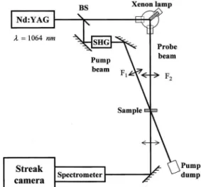
The experimental setup is shown on Fig. 1. We use a mode-locked Nd:YAG laser delivering 30-ps pulses either at 532 nm or at 1064 nm, at a repetition rate of 8 Hz. The beam is split into two parts; the first one, focused into the nanotube suspensions by use of a 150-mm focal-length lens, is used as a pump beam. After passing through the sample, the transmitted pump beam is blocked by a dump. The polychromatic probe beam is ob-tained by focusing the second Nd:YAG beam on a tung-sten electrode under xenon atmosphere (pressure 2 bars), leading to a broadband emission (from 350 nm to 700 nm) with a typical lifetime of 50 ns (rise time of ;30 ps). The resulting emitted light is collimated by a short-focal-length lens and focused into carbon-nanotube cells, nearly collinear to the pump beam, the probe diameter in the cell being always smaller than the pump-beam diameter (;450 mm). The probe transmittance is recorded with a monochromator coupled with a streak camera (ARP, Strasbourg, France, resolution of 8 ps) in single-shot mode. A retardation line on the pump path ensures that the sample is probed before and after perturbation. Such a technique allows both spectrally and temporally re-solved measurements to be obtained. In order to avoid cumulative thermal effects, we use a circulation system in the cells to refresh nanotube suspensions between con-secutive shots. The signal-to-noise ratio is enhanced by averaging 100 consecutive measurements.
Fig. 1. Pump–probe experimental setup for pump wavelengths 532 and 1064 nm and probe wavelengths from 400 nm to 700 nm. BS, beam splitter; F1 and F2, 150-mm and 100-mm focal length, respectively.
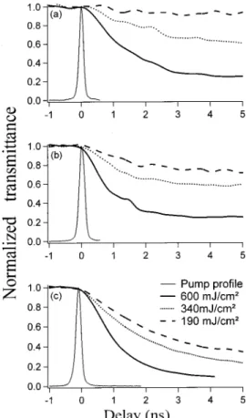
Figure 2 displays the evolution of probe transmittance at three different pump fluences (190 mJ/cm2, 350 mJ/cm2, and 630 mJ/cm2), for SWNT suspended in both
water and chloroform solvents and for MWNT suspended in water. The pump wavelength is 532 nm and the samples are probed at 480 nm, sufficiently far from the pump wavelength to allow an efficient filtering of scat-tered pump light. The nonlinear response of the samples is not instantaneous, as expected from the probable origin of optical-limiting behavior of carbon nanotubes. In fact, the perturbation begins a few hundreds of picoseconds af-ter the pump pulse; then the minimum probe transmit-tance is reached in a few nanoseconds (typically 3–5 ns, depending on pump fluence). As the pump fluence in-creases, the perturbation occurs earlier after the pump pulse and develops faster; however, no limiting of 30-ps pulses occurs. Such a behavior is consistent with previ-ously published picosecond and nanosecond pump–probe results15,16and is in accordance with the proposed mecha-nism of nonlinear scattering: scattering centers are gen-erated both by solvent-bubble growth and by phase change (sublimation) of the carbon nanotubes, due to in-tense heating of the particles and subsequent heat trans-fer. The characteristic times for the growth of the scat-tering centers are in the nanosecond range.
Let us compare the different behaviors of the three kinds of samples (Fig. 2). In the same solvent (water), SWNT and MWNT exhibit similar responses, but with
faster growth of the scattering centers in the case of SWNT. The delay between the pump pulse and the be-ginning of the probe-transmittance decrease is shorter for SWNT than for MWNT at low pump fluences. This may be related to the smaller external specific area of MWNT as compared with SWNT, which may slow down thermal-transfer processes. Results obtained with SWNT sus-pended in both liquids (water and chloroform) show a no-ticeable solvent effect, with a decrease of the probe transmittance significantly larger for the chloroform sus-pension than for the water sample. It has been shown7,16 that the thermodynamic properties of chloroform favor solvent-bubble growth, leading to larger scattering cen-ters.
In order to better understand the nonlinear phenomena in carbon nanotube suspensions, we studied the wave-length dependence of the probe perturbation at a fixed pump wavelength (532 nm or 1064 nm). The temporal shapes of the curves obtained for different pump fluences are similar to those in Fig. 2, but the magnitude of the drop of the transmittance is strongly wavelength depen-dent. Figures 3(a) and 3(b) compare the wavelength de-pendence of the probe transmittance measured at 4 ns af-ter the top of the pump pulse, for 532-nm and 1064-nm pump wavelengths (See an example of the total time de-pendence in Fig. 4). The behavior is the same for the two wavelengths within the experimental errors. We observe
Fig. 2. Probe transmittance, normalized to the linear transmit-tance as function of delay between the probe at 480 nm and the pump at 532 nm for different picosecond pump fluences (from 190 mJ/cm2to 600 mJ/cm2) for (a) MWNT in water, SWNT in (b)
water, and in (c) chloroform. The linear transmittance is 80% for all samples.
Fig. 3. Normalized probe transmittance as a function of probe wavelength for SWNT in water and chloroform and for MWNT in water, for a pump wavelength of (a) 532 nm and (b) 1064 nm. The delay between the pump and the probe is 4 ns, and the pump energy is 600 mJ/cm2. The solid curve is a fit obtained with Mie
a broadband-limiting efficiency from 400 nm to 650 nm for all the samples. As expected, from Mie-scattering theory (solid curve in Fig. 3(a); see Section 4), the shorter the wavelength, the lower the transmittance. Indeed, for submicronic particles, scattering is more efficient when the size of the scattering centers is close to the wave-length, or reciprocally, for given scattering centers, when the wavelength decreases. A quantitative analysis of the wavelength dependence of the transmittance allows de-termination of the concentration and average radius of the scattering centers. Such an analysis is performed in Section 4.
B. Nanosecond Studies
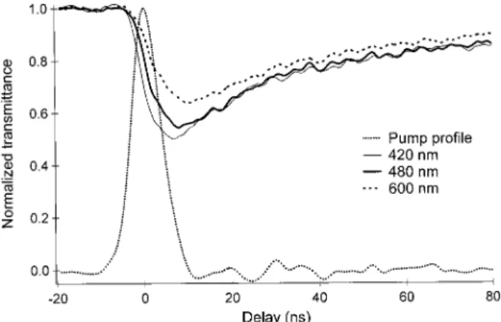
In order to better understand the different optical-limiting performances obtained in the nanosecond re-gime, we carried out nonlinear-transmittance experi-ments for different pulse durations. The nanosecond data support the results presented in Subsection 3.A. We realized similar pump–probe experiments with a Nd:YAG laser delivering 10-ns pulses width at 532 nm. As for picosecond pump–probe experiments, we per-formed transmittance measurements for different probe wavelengths (from 400 nm to 650 nm) and recorded the probe transmittance of the carbon-nanotube samples at several delays (from 1 to 80 ns). Figure 4 shows the
transmittance kinetics of SWNT suspended in water, for a pump fluence of 200 mJ/cm2and for three different probe wavelengths: 420, 480, and 600 nm. The minimum of transmittance is reached at ;7 ns and ;10 ns after the top of the pump pulse for SWNT and MWNT (not shown), respectively. As is explained in Section 4, this minimum corresponds to a maximum volume fraction of vapor bubbles, and thus to maximum extinction, followed by a slow relaxation process. These curves are in agreement with our previously published results,17 but
polychro-matic measurements allow performance of a deeper analysis.
Figure 5 shows the limiting curves obtained with the same SWNT/chloroform sample at the same wavelength (532 nm), obtained by two different lasers under similar focusing conditions: a Nd:YAG laser delivering 5-ns FWHM pulses and an optical parametric oscillator deliv-ering 2-ns FWHM pulses. The limiting performances ob-tained with 5-ns pulses are considerably better than those obtained at 2 ns, with a lower limiting threshold (;40 mJ/cm2 instead of 150 mJ/cm2) and a transmittance
re-duced by a factor of 2 for incident fluences .0.5 J/cm2.18 The explanation is that in the nanosecond regime, the maximum size of the scattering centers is reached only af-ter the end of the incident pulses, even at 10 J/cm2.
Therefore one observes a strong pulse-duration depen-dence of the limiting performances. This also explains that no optical limiting at all is observed in the picosecond range.
4. INTERPRETATION
In our previous investigations on the optical-limiting ori-gin in carbon nanotube suspensions,16,17we demonstrated a strong nonlinear-scattering effect principally due to the growth of vapor bubbles, which can be solvent bubbles or carbon vapor bubbles, depending on the incident fluence and on the thermodynamic properties of the solvent. In all cases, the threshold for solvent-bubble formation is significantly lower than the carbon sublimation threshold.16,17 However, solvent-bubble growth is much
slower than expansion of vaporized carbon cavities.16,17 For example, with 5-ns pulses, solvent-bubble formation occurs at incident fluences as low as 10 mJ/cm2but only a few tens of nanoseconds after the pump pulse and thus does not contribute to optical limiting.17 The limiting threshold, ;150 mJ/cm2 at 1064-nm pump wavelength, corresponds to carbon-nanotube sublimation. On the contrary, solvent-bubble growth contributes very effi-ciently to optical limiting of 80-ns duration pulses in car-bon nanotube/chloroform suspensions.18
The analysis of the extinction of the polychromatic probe beam allows estimation of the evolution of size and dimensions of the scattering centers during and after the pump pulse, from Mie theory for both pump temporal re-gimes (30 ps and 10 ns). For this, we developed a simple model, where we considered the following approxima-tions: the bubbles are spherical, their index of refraction is 1, and they are considered to be monodisperse in size. Moreover, we assume that only simple scattering occurs (we neglect multiple scattering). The assumption of spherical bubbles may be erroneous for carbon nanotubes,
Fig. 4. Probe perturbation at 420, 480, and 600 nm for SWNT in water at 10 ns and at 532 nm for input fluence of 200 mJ/cm2.
The linear transmittance is 80% for all samples.
Fig. 5. Optical-limiting curves of SWNT suspended in chloro-form for 2- and 5-ns pulse widths at 532 nm. The linear trans-mittance is 70% for all samples.
but, beside the simplification it brings, it is justified by the fact that the nanotubes are entangled in coils when in solution.
The transmittance of the samples follows the Beer– Lambert law:
TN5 exp~ 2hlsext!, (4.1)
where TN is the transmittance,h is the volume
concen-tration of scattering centers (m23), l is the thickness of
the cell (m), and sextis the extinction cross section (m2),
which reads
sext5 sabs1 ssc, (4.2)
where sscand sabsare the scattering and absorption cross sections, respectively.
In view of the high linear transmission (.90% when corrected for reflection losses), one can neglect sabs, so
that sext. ssc. Equation (4.1) is therefore
ln~TN! 5 2hlssc. (4.3)
According to the Mie theory,24this scattering cross sec-tion depends on the scattering center radius and the wavelength: for spherical bubbles in a simple scattering regime, it is given by ssc5 2p k2 n51
(
` ~ 2n 1 1!~uanu21 ubnu2!, (4.4)where k is the light wave vector, and an and bn are the
scattering coefficients, defined as
an5 mCn~ mx !Cn8~ x ! 2 Cn~ x !Cn8~ mx ! mCn~ mx !jn8~ x ! 2 Cn8~ mx !jn~ x ! , bn5 Cn~ mx !Cn8~ x ! 2 mCn~ x !Cn8~ mx ! Cn~ mx !jn8~ x ! 2 mCn8~ mx !jn~ x ! . (4.5) Cn and jn are the Riccati–Bessel functions: Cn
5 rJn(r) and jn5 rhn(1)(r), where Jn(r) are the
spheri-cal Bessel functions, and hn(1)(r) are the spherical Hankel
functions of first order. x and m correspond to the size parameter and the relative refractive index, respectively, defined as functions of the refractive indices of the par-ticle (n) and of the surrounding medium (n1) and the
sphere radius (R) as
x 5 2pnR
l , (4.6)
m 5 n1
n . (4.7)
Therefore from the equations above, one sees that the wavelength and the particle radius determine the scatter-ing cross section in a unique manner. On the other hand, the scattering cross section depends on the volume con-centrationhthrough Eq. (4.3). One can therefore fit each nanosecond and picosecond experimental curve displayed in Section 3 (Fig. 3) with only two free parameters R and
h. This allows obtention of the evolution of average ra-dius and concentration of the scattering centers in the medium. This procedure is of course not very precise, but it nevertheless gives a good order of magnitude of these parameters. This adjustment is more precise when the radii are small, on the condition that the scattered signal is strong enough to yield measurable effects.
Moreover, by fitting the transmittance curves at differ-ent delays, in the nanosecond regime (like those pre-sented in Fig. 4), one determines the temporal evolution of the size and of the concentration of scattering centers, and we obtain the gas volume fraction (averaged on the probe light path), given by V 5 (4p/3)hR3.
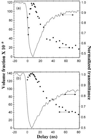
Figure 6 displays the volume fractions of the gas ob-tained from nanosecond pump–probe experimental re-sults at 532 nm with SWNT and MWNT, both suspended in water. They increase rapidly and reach maxima of 1.4 3 1027and 1.2 3 1027, and 7 ns and 10 ns, after the
top of the pump pulse for SWNT and MWNT, respectively. The decrease of the volume is much slower than the in-crease due to a slow cooling down of the medium after the pump pulse. We note that the (half-life) relaxa-tion time is longer for SWNT (t ' 30 ns) than for MWNT (t ' 15 ns), but the reason for this is still unclear. These relaxation times are the same as those obtained for relax-ation of the probe perturbrelax-ation. As evidenced in Fig. 6, we have a good correlation between the time evolution of both the probe transmission and the gas volume fraction inferred from the multiwavelength probe-transmittance measurements.
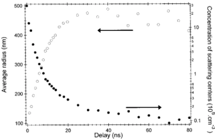
Figure 7 shows the evolution of the concentrationhand average radius R of scattering centers for SWNT in water. Surprisingly, the concentration of scattering centers de-creases very rapidly, in the first few nanoseconds
follow-Fig. 6. Evolution of the gas volume fraction (closed circle) and normalized transmittance of the probe (solid curve) for (a) SWNT and for (b) MWNT suspended in water, in the nanosecond re-gime, at 532 nm and for input energy of 200 mJ/cm2. Delay zero
corresponds to the maximum of the pump pulse. The linear transmittance is 80% for all samples.
ing the top of the pump pulse. Symmetrically, the aver-age radius increases and reaches a plateau after approximately 25 ns. The decrease of the concentration is associated with an increase of the average radius be-cause of a competition between coalescence and condensa-tion of vapor bubbles.
With the results of the picosecond experiments, one can focus on the beginning of the bubble growth (Fig. 8). For
SWNT, the average scattering radius is lower in chloro-form than in water suspensions, indicating that coales-cence is more important in water suspensions, leading to larger vapor bubbles. However, the concentration of scattering centers is more important in chloroform than in water suspensions. These features show that the be-haviors in the two solvents are quite different: the probe beam is scattered by a large number of small vapor bubbles in chloroform suspensions, whereas in water sus-pensions, it is scattered by a smaller number of larger va-por bubbles. This difference can be related to the higher surface tension at the liquid/gas interface in water than in chloroform: to minimize surface energy, aggregation and subsequent coalescence of vapor bubbles are faster in water than in chloroform, leading to the formation of larger scattering centers in the few nanoseconds following the pump pulse. With a pump wavelength of 1064 nm, we obtained similar results.
5. CONCLUSION
We carried out picosecond and nanosecond pump–probe experiments with a variable probe wavelength. These experiments allow determination of the concentration and average radius of scattering centers as well as their vol-ume fraction as a function of time, by a simple extinction model based on Mie theory. From that analysis, we show a clear correlation between the evolutions of the probe transmittance and of the gas volume fraction. In water suspensions, coalescence of vapor bubbles begins in the first nanosecond following the pump pulse. The coales-cence effect is slower in chloroform suspension due to lower surface tension at the liquid/gas interfaces. In chloroform suspensions, the probe is scattered by many small vapor bubbles while in water suspensions, it is scat-tered by a smaller number of larger vapor bubbles. How-ever, chloroform suspensions exhibit a better optical-limiting efficiency than water suspensions in the nanosecond regime. The pump–probe experiments also confirmed that carbon-nanotube suspensions are efficient only for nanosecond and longer pulses. The coalescence phenomenon was recently confirmed by shadowgraphic measurements, which will be published elsewhere.
ACKNOWLEDGMENTS
The authors greatly appreciate the high-quality samples from S. Tahir and P. Bernier. We thank M. Andrieux and F. Lafonta for their help and fruitful discussion. E. Ang-laret acknowledges the De´le´gation Ge´ne´rale pour l’Armement for financial support.
REFERENCES
1. K. Nashimoto, R. Pachter, B. W. Wessels, J. Shmulovich, A. K.-Y. Jen, K. Lewis, R. Sutherland, and J. W. Perry, eds., Thin Films for Optical Waveguides Devices and Materials for Optical Limiting, Vol. 597 of MRS Proceedings Series (Materials Research Society, Warrendale, Pa., 1999). 2. R. Bozio, F. Kazjar, and M. Meneghetti, eds., Proceeding of
Second International Workshop on Optical Power Limiting (Gordon and Breach, London, 2002).
3. J. W. Perry, ‘‘Organics and metal-containing reverse satu-rable absorbers for optical limiters,’’ in Nonlinear Optics of
Fig. 7. Evolution of the concentration and of the average radius of scattering centers for SWNT in water, for 532-nm nanosecond pump pulses and for input energy of 200 mJ/cm2. Delay zero
corresponds to the maximum of the pump pulse. The linear transmittance is 80% for all samples.
Fig. 8. Evolution of (a) the concentration and of (b) the average radius of scattering centers for SWNT and MWNT in water and SWNT in chloroform, for 532-nm picosecond pump pulses for in-put energy of 600 mJ/cm2. Delay zero corresponds to the
maxi-mum of the pump pulse. The linear transmittance is 80% for all samples.
Organics Molecules and Polymers, H. S. Nalwa and S. Miyata, eds. (CRC Press, Orlando, Fla., 1997), pp. 813–840. 4. P. Feneyrou, ‘‘Broadband optical limiting using tandem fil-ters with multiphoton absorber and reverse saturable ab-sorbers,’’ J. Opt. Nonlinear Phys. Mat. 9, 523–530 (2000). 5. R. W. Boyd, Nonlinear Optics (Academic, New York, 1992). 6. B. L. Justus, A. L. Huston, and A. J. Campillo, ‘‘Broadband thermal optical limiter,’’ Appl. Phys. Lett. 63, 1483–1486 (1993).
7. K. J. McEwan, P. K. Milsom, and D. B. James, ‘‘Nonlinear optical effects in carbon suspensions,’’ Proc. SPIE 3472, 42–52 (1998).
8. K. M. Nashold and D. P. Walter, ‘‘Investigations of optical limiting mechanisms in carbon particle suspensions and fullerene solutions,’’ J. Opt. Soc. Am. B 12, 1228–1237 (1995).
9. K. Mansour, M. J. Soileau, and E. W. Van Stryland, ‘‘Non-linear optical properties of carbon-black suspensions (ink),’’ J. Opt. Soc. Am. B 9, 1100–1109 (1992).
10. V. Joudrier, P. Bourdon, F. Hache, and C. Flytzanis, ‘‘Char-acterization of nonlinear scattering in colloidal suspensions of silica particles,’’ Appl. Phys. B 70, 105–109 (2000). 11. S. Iijima, ‘‘Helical microtubules of graphitic carbon,’’ Nature
354, 56–58 (1991).
12. L. Vivien, E. Anglaret, D. Riehl, F. Bacou, C. Journet, C. Goze, M. Andrieux, M. Brunet, F. Lafonta, P. Bernier, and F. Hache, ‘‘Single-wall carbon nanotubes for optical limiting,’’ Chem. Phys. Lett. 307, 317–319 (1999), and erratum 312, 617 (1999).
13. S. R. Mishra, H. S. Rawat, S. C. Mehendale, K. C. Rustagi, A. K. Sood, R. Bandyopadhyay, A. Govindaraj, and C. N. R. Rao, ‘‘Optical limiting in single-walled carbon nanotube suspensions,’’ Chem. Phys. Lett. 317, 510–514 (2000). 14. L. Vivien, E. Anglaret, D. Riehl, F. Hache, F. Bacou, M.
An-drieux, F. Lafonta, C. Journet, C. Goze, M. Brunet, and P.
Bernier, ‘‘Optical limiting properties of singlewall carbon nanotubes,’’ Opt. Commun. 174, 271–275 (2000).
15. X. Sun, Y. Xiong, P. Chen, J. Lin, W. Ji, J. Hong Lim, S. S. Yang, D. J. Hagan, and E. W. Van Stryland, ‘‘Investigation of an optical limiting mechanism in multiwalled carbon nanotubes,’’ Appl. Opt. 39, 1998–2001 (2000).
16. L. Vivien, D. Riehl, E. Anglaret, and F. Hache, ‘‘Pump-probe experiments at 1064 nm in singlewall carbon nanotube sus-pensions,’’ IEEE J. Quantum Electron. 36, 680–686 (2000). 17. L. Vivien, D. Riehl, F. Hache, and E. Anglaret, ‘‘Nonlinear scattering origin in carbon nanotube suspensions,’’ J. Opt. Nonlinear Phys. Mat. 9, 297–308 (2000).
18. L. Vivien, D. Riehl, P. Lanc¸on, F. Hache, and E. Anglaret, ‘‘Pulse duration and wavelength effects on the optical lim-iting behavior of carbon nanotube suspensions,’’ Opt. Lett.
26, 223–225 (2001).
19. J. E. Riggs, D. B. Walker, D. L. Carroll, and Y.-P. Sun, ‘‘Op-tical limiting properties of suspended and solubilized car-bon nanotubes,’’ J. Phys. Chem. B 104, 7071–7076 (2000). 20. C. Journet, W. K. Maser, P. Bernier, A. Loiseau, M. Lamy de
la Chapelle, S. Lefrant, P. Deniard, R. Lee, and J. E. Fis-cher, ‘‘Large-scale production of single-walled carbon nano-tubes by the electric-arc technique,’’ Nature 388, 756–758 (1997).
21. L. Vaccarini, C. Goze, R. Aznar, V. Micholet, C. Journet, and P. Bernier, ‘‘Purification procedure of carbon nanotubes,’’ Synth. Metals 103, 2492–2493 (1999).
22. S. Rols, E. Anglaret, J. L. Sauvajol, G. Coddens, and A. J. Dianoux, ‘‘Neutron scattering studies of the structure and dynamics of nanobundles of single wall carbon nanotubes,’’ Appl. Phys. A 69, 1–72 (1999).
23. S. Rols, R. Almairac, L. Henrard, E. Anglaret, and J. L. Sauvajol, ‘‘Diffraction by finite-size crystalline bundles of single wall nanotubes,’’ Europhys. J. B 10, 263–270 (1999). 24. C. F. Bohren and D. R. Huffman, Absorption and Scattering