HAL Id: hal-00613643
https://hal.archives-ouvertes.fr/hal-00613643v2
Preprint submitted on 12 Aug 2011HAL is a multi-disciplinary open access
archive for the deposit and dissemination of sci-entific research documents, whether they are pub-lished or not. The documents may come from teaching and research institutions in France or abroad, or from public or private research centers.
L’archive ouverte pluridisciplinaire HAL, est destinée au dépôt et à la diffusion de documents scientifiques de niveau recherche, publiés ou non, émanant des établissements d’enseignement et de recherche français ou étrangers, des laboratoires publics ou privés.
Exploiting the Time-Reversal Operator for Adaptative
Optics, Selective Focusing and Scattering Pattern
Analysis
Sébastien Popoff, Alexandre Aubry, Geoffroy Lerosey, Mathias Fink,
Albert-Claude Boccara, Sylvain Gigan
To cite this version:
Sébastien Popoff, Alexandre Aubry, Geoffroy Lerosey, Mathias Fink, Albert-Claude Boccara, et al.. Exploiting the Time-Reversal Operator for Adaptative Optics, Selective Focusing and Scattering Pat-tern Analysis. 2011. �hal-00613643v2�
Exploiting the Time-Reversal Operator for Adaptative Optics, Selective
Focusing and Scattering Pattern Analysis
S. M. Popoff, A. Aubry,∗ G. Lerosey, M. Fink, A. C. Boccara, and S. Gigan Institut Langevin, ESPCI ParisTech, CNRS UMR 7587,
Universités Paris VI & VII, INSERM, ESPCI, 10 rue Vauquelin, Paris, 75231, France
(Dated: 12 août 2011)
Résumé
We report on the experimental measurement of the backscattering matrix of a weakly scattering me-dium in optics, composed of a few dispersed gold nanobeads. The DORT method (Decomposition of the Time Reversal Operator) is applied to this matrix and we demonstrate selective and efficient focusing on individual scatterers, even through an aberrating layer. Moreover, we show that this approach provides the decomposition of the scattering pattern of a single nanoparticle. These results open important perspectives for optical imaging, characterization and selective excitation of nanoparticles.
The propagation of waves in inhomogeneous media is a fundamental problem which implies applications in many domains of wave physics, ranging from optics or acoustics to solid-state physics, seismology, medical imaging, or telecommunications. Conventional focusing and ima-ging techniques based on the Born approximation generally fail in aberrating or strongly scattering media due to the phase distorsions and the multiple scattering events undergone by the incident wavefront. Recent advances in light manipulation techniques have allowed great progresses in optical focusing and imaging through complex media. Following pioneering works in ultrasound [1, 2], Vellekoop et al. [3] showed how light can be focused spatially through a strongly scattering medium by actively shaping the incident wavefront with a spatial light modulator (SLM). Seve-ral groups [4–6] have recently extended this approach to the time domain and demontrated the spatio-temporal focusing of femtosecond pulses through highly scattering media.
A general treatment of such linear complex media is provided by the scattering matrix forma-lism, as defined in [7] for instance. For ultrasound or microwaves, such a formalism is particularly appropriate as the wave field can be generated and detected by arrays of independent elements. Po-poff et al. [8, 9] recently extended this method to optics and measured the transmission matrix for light between a SLM (emission) and a CCD camera (reception) through a scattering medium. The latter is a subpart of the scattering matrix linking the forward scattered field to the incident field. The experimental access to this transmission matrix is particularly important since it contains many informations on the propagation medium. In particular, it should give access to the open channels that allow to transmit light through the scattering sample [7, 10, 11].
In this Letter, we study another subpart of the scattering matrix : the backscattering matrix K (BM). The knowledge of the BM brings more fundamental insight into the medium. Initially developed for ultrasound [12–14] and then extended to microwaves [15, 16], the DORT method (French acronym for Decomposition of the Time Reversal Operator) takes advantage of the BM to focus iteratively by time reversal processing on each scatterer of a multi-target medium. Derived from the theoretical study of the iterative time reversal process, this approach relies on the diago-nalization of the time reversal operator KK†. A one-to-one association between each eigenstate and each scatterer allows focusing on each scatterer by transmitting the computed eigenvectors. Technically, a singular value decomposition (SVD) of the BM is used to compute the eigenstate of the time reversal operator. In this letter, we will demonstrate the DORT method in the optical regime and show its efficiency in weakly scattering media. An experimental setup is proposed to record the BM in optics. Using the DORT method, we perform selective focusing on 100 nm
gold nanoparticles through an aberrating medium, opening an original alternative to conventional adaptive optics [17]. In a second part, we show how the DORT method can be used to discrimi-nate and selectively excite the different scattering patterns of a single nanoparticle, hence paving the way towards a better characterization, imaging and control of nano-objects for instance in plasmonics [18] or for super-resolution [19].
The experimental setup used for the measurement of the BM is displayed in Fig. 1. To generate the incident wavefront, the beam from a single mode laser at 532 nm is expanded and spatially modulated by a liquid crystal SLM. Using a polarizer and an analyzer, we choose an appropriate combination of polarizations before and after the SLM to achieve a 2π-phase modulation with a residual amplitude modulation below 15%. Light is focused onto the surface of a glass slide on which is deposited a dilute solution of 100 nm isotropic gold beads. We image the output backscattered field pattern onto a first CCD camera (CCD1) thanks to a beamsplitter. To minimize specular reflections, the two polarizers are in a cross-polarized configuration. A reference arm can be used to make the backscattered field interefere with a plane wave onto CCD1. The system is set such that a pixel of the SLM corresponds approximately to an incident k-vector. An aberrating slab is placed 0.5 mm from the image plane between the scattering sample and the objective. It consists in an irregular PDMS polymer layer with a mean thickness of 200 µm deposited on a cover glass. The CCD1 records the image of the intensity in the plane containing the gold particles, with and without the aberrator. For control purposes, another CCD camera (CCD2) images the same plane in transmission, through a high NA objective.
In the experimental setup shown in Fig. 1, the input and output modes correspond to SLM and CCD1 macropixels, respectively. The BM corresponds to a matrix K whose complex coefficients kmn connect the optical response (in amplitude and phase) between the nthSLM pixel to the mth
CCD1 pixel. In other words, the complex optical field on the mth outgoing pixel reads Emout = P
nkmnEnin with Enin the field on the nth input pixel. K is of dimension M × N , with M and N
the number of pixels contained by CCD1 and the SLM, respectively. The inter-element responses kmnare measured following the procedure described in [8], i.e using phase-shifting interferometry
and a Hadamard input basis.
A singular value decomposition (SVD) of the BM consists in writing K = UΣV†where the subscript†denotes the transpose conjugate. Λ is a diagonal matrix containing the real positive sin-gular values λi in a decreasing order λ1 > λ2 > · · · > λN. U and V are unitary matrices whose
CCD1 Laser SLM L L’ L1 Aberrating layer Pinhole CCD2 BS BS’ Gold beads on glass slide MO2 MO1 L2 Reference arm P3 P1 P2
FIGURE 1: Schematic of the apparatus. The 532 nm laser is expanded and reflected off a Holoeye LC-R 2500 liquid cristal SLM. Polarization optics (polarizer P1 and analyser P2) allow phase modulation. The
modulated beam is focused on the plane containing the gold particules by a 20x objective (NA = 0.5) and the backscattered intensity is imaged by a first CCD-camera (CCD1). The second CCD-camera (CCD2) images the same plane in transmission with a 60x oil immersion objective (NA = 1.4). Analysers P2 and P3
are oriented in a cross-polarized configuration. L, lens. BS, beamsplitter.
method consists in using the SVD of the BM to efficiently detect and separate the responses of several scatterers in homogeneous or weakly heterogeneous media [13]. Indeed, under the single scattering approximation and for pointlike scatterers, each scatterer is associated mainly to one significant eigenstate. The latter is linked to a non-zero singular value λi that relates to the
scat-terer reflectivity. In first approximation, each singular vector Vi of K corresponds to the complex
amplitude mask which, when applied to the SLM, focuses onto the associated scatterer.
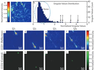
Figs. 2 and 3 show the experimental results of the DORT method applied to the BM matrix when several 100 nm gold beads are dispersed on the slide placed behind an aberrating layer. For this experiment, we have used the field generated by the unmodulated part of the illumination as the reference for the interferometric measurement rather than the plane wave from the reference arm. This method detailed in [8] allows for a better stability without being detrimental to focusing applications. The numbers of pixels have been fixed to N = M = 1024. Fig. 2(a) shows the image measured by CCD1 in reflection when a plane wave is sent from the SLM. The image of the medium is drastically damaged by the aberrating layer : the number of gold beads as well as their position and reflectivity cannot be deduced from this image. In contrast, the DORT method gives an unambiguous answer to these questions. The singular value distribution (Fig. 2(b)) of the BM exhibits two parts. The continuum of low singular values is associated to the noise in
0 1 2 3 4 5
4 3 2 1
Singular Values Distribution Noise
Normalized Singular Values
Singular Values C oun t U1 U2 U3 U4 5μm CCD1 (R eflec tion) CCD2 ( Con tr ol) 0 0.2 0.4 0.6 0.8 1 Nor maliz ed I nt ensit y 0 0.2 0.4 0.6 0.8 1 Nor maliz ed I nt ensit y 0 10 20 30 40 0 0.02 0.04 0.06 0.08 4 3 2 1 Nor maliz ed I nt ensit y a. b. g. h. i. 5μm 5μm 5μm 5μm j. i. h. f. e. c. d. 5μm 5μm 5μm 5μm j. i. g. h.
FIGURE2: Experimental results for selective focusing on nanobeads through an aberrating layer using the DORT method. a. aberrated image of the object plane on CCD1 in reflection for a plane wave illumination b., singular value distribution of the measured BM. c.-f. ( resp. g.-j.) ; images in reflection by camera CCD1 ( resp. in transmission by the control camera CCD2), when sending the four first singular vectors. All images from CCD1 (resp. CCD2) share the same intensity scale.
the BM (residual specular reflections, laser fluctuations, CCD readout noise etc.). A few higher singular values are associated to the brightest gold nanoparticles since the singular value is directly proportional to the reflectivity of the scatterer. The input singular vector Vi corresponds to the
wave-front focusing on the ith particle and the output singular vector U
i is the corresponding
scattering pattern measured by CCD1 in reflection (see Figs. 2(c,d,e,f)). Figs. 2(g,h,i,j) correspond to the control images measured in transmission by CCD2, when the first four singular vectors Vi are back-propagated from the SLM. These images show the selective focusing performed by
DORT : each singular vector back-propagates selectively on one gold bead without illuminating the other ones. Quantitatively, an intensity enhancement of ∼ 20 is observed on the four gold beads position when DORT focusing is performed compared to plane wave illumination.
Fig. 3 shows explicitly the effect of aberrations by comparing the singular vectors V1 and U1
(associated to the brightest scatterer) with and without the aberrating layer. Figs. 3(b) and (c) dis-play the phase of V1 on the SLM in both situations. In free space, the wavefront focusing on
a particle corresponds to a Fresnel phase zone plates (Fig. 3(b)). In contrast, in presence of an aberrating layer (Fig. 3(c)), V1 is strongly modified to compensate for the wavefront distortions.
compa-rison of both figures shows the damaging effect of the aberrating layer and highlights the benefits of the DORT method in this configuration.
5μm 5μm
b. c. d.
a.
FIGURE3: Phase of the first input singular vector V1 (b, c) and the corresponding focal spots recorded by
CCD1 (a, d) in free space and in presence of an aberrating layer, respectively.
So far, we made the assumption that each scatterer is only associated to one single singular value. However, this is not strictly true : there can be several singular values associated to a single scatterer, each one corresponding to a different scattering pattern of the particle [20–22]. To in-vestigate the different eigenstates associated to one nanoparticle, we now study analytically and experimentally the DORT analysis of the BM without any aberrating layer and with only one gold particle in the observation area.
Let us assume that the incident field is linearly polarized along x, z is the propagation axis and y the polarization observed in reflection (cross-polarized configuration). The BM can be decom-posed into the product of three matrices : K = K00.¯α.K0. Here K0is a 3 × N matrix describing the propagation of light from the N pixels of the SLM to the scatterer. The three lines of K0 corres-pond to the different orientations of the electric field at the particle position. ¯α is the polarisability tensor of the particle linking the local electric field to the dipole moment p of the particle. K00 is a M × 3 matrix which connects the dipole moment p to the y-component of the electric field measured on the M pixels of CCD1. We will assume that the particle is isotropic : ¯α = αI with α the particle polarizability and I the identity matrix.
The electric field illuminating the particle in the focal plane can be deduced from [23, 24] and leads to the following expression for the coefficients of K0:
k1j0 = I0(θj1, ρs) + I2(θ1j, ρs) cos(2φs) | {z } negligible (1) k2j0 = I2(θj1, ρs) sin(2φs) (2) k3j0 = 2jI1(θj1, ρs) cos(φs) (3)
φs and ρs are the polar coordinates of the particle in the focal plane (see Fig. 4(a)). θj1 < θmax1 is
functions I0, I1and I2 are given by :
I0(θ, ρ) =
√
cos θ sin θ(1 + cos θ)J0(2πρ sin θ) (4)
I1(θ, ρ) =
√
cos θ sin2θJ1(2πρ sin θ) (5)
I2(θ, ρ) =
√
cos θ sin θ(1 − cos θ)J2(2πρ sin θ) (6)
with J0, J1 and J2 the zero, first and second order spherical Bessel functions of the first kind,
respectively.
The y-component of the backscattered field can be also deduced from the calculations of [23] and leads to the following expression for K00 :
kk100 = Z θmax2 0 dθ2I2(θ2, ρk) sin(2φk) (7) kk200 = Z θmax2 0 dθ2[I0(θ2, ρk) + I2(θ2, ρk) cos(2φk) | {z } negligible ] (8) kk300 = 2j Z θmax2 0 dθ2I1(θ2, ρk) sin(φk) (9)
ρk and φkare the polar coordinates of the kth pixel of CCD1 and θ2 is the angle made by a beam
diffracted by the particle with the optical axis before going through the microscope objective (see Fig. 4(b)). Hence, the BM depends on the following parameters : the position of the particle in the focal plane (φs,ρs), the numbers of SLM and CCD elements (N and M ) and the input and output
maximum angles (θ1max and θmax2 ). θ2max is directly given by the numerical aperture of the optical system, but θmax
1 can be smaller if the area of illumination is smaller than the area of the pupil of
the microscope objective. Theory predicts that the x, y and z components of the particle dipole moment p give rise to different scattering patterns : monopolar for y (Eq.8), bipolar for z (Eq.9) and quadrupolar for x (Eq.7) (see Fig.4(d)). Those scattering patterns are strictly orthogonal if they are observed over a solid angle Ω = 2π. Hence, in theory, the output singular vectors Uiof K
should correspond to the different scattering patterns of the nanoparticle (i.e the columns of K00). In practice, this is not strictly true since only a limited part of the half space is accessible in our experiment.
Our theoretical predictions are now confronted to the experimental results. As an exact measu-rement of the output singular vectors is needed, the complex wave field has to be measured directly. A reference arm is now used to make the backscattered wave interfere with a reference plane wave on CCD1 (see Fig.1). The output singular vectors Ui correspond then to the complex scattering
b. θj φs ρs 0 0.5 1 1.5 2 2.5 3 0 2 4 6 0 0 5
10 Singular Values Distribution
Singular
V
alues
Cou
nt
Singular Values Distribution
Singular V alues Cou nt a. c. d. SLM Focal Plane φk ρk θ φs ρs CCD pixel j Focal Plane pixel k 0.5 1 1.5 2 2.5 3 U3 U2 U1 U3 U2 U1 1 -1 0 -1 0 1μm 1μm
FIGURE4: Singular value decomposition of the experimental and theoretical BM with a single scatterer. (a) and (b) represent the emission and the recording geometry of the experiment.(c) and (d) show the singular value distributions of the measured and calculated BM. The three first output singular vectors are shown in the insets.
patterns of the particle. The number N of controlled segments on the SLM has been lowered to 16 for stability contraints over the time of the experiment. The result of the DORT analysis is shown in Fig.4. The experimental and theoretical singular values distribution as well as the three first out-put singular vectors of the BM are compared in Fig.4(c) and (d), respectively. The experimental values of θ1maxand θ2maxhave been used for our theoretical calculations (θ1max = 22˚, θmax
2 = 68˚
). The position of the particle in the focal plane has been arbitrarily fixed (φs = 7/8π, ρs = 665
nm) such that the theoretical and experimental ratios between the first and the second singular values are equal.Our theoretical calculations predict that only the three first singular values are non-zero, each one corresponding to the independent scattering patterns of the three orthogonal dipolar radiations (along x, z and y resp.). The experimental results display a continuum of low singular values corresponding to noise and three higher singular values (Fig.4(d)). The two first output singular vectors match the scattering patterns of the x− and z−components of the nano-particle dipole moment, as predicted theoretically. The third output singular vector has a geometry comparable to the second one, but is more affected by the experimental noise since a significant
part of its energy is observed outside the particle. This singular vector might correspond to a cou-pling between the second singular state (z−component) and eigenmodes of the noise background. The scattering pattern associated to the y−component of the dipole moment is drowned in noise and could not be observed.
The DORT method allows to excite independently each component of the nanoparticle dipole moment : such an experiment would require to increase the number of SLM segments for quan-titative results and a near field scanning optical microscope (NSOM) to probe the near-field of the nanoparticle. For larger scatterers, the singular spectrum may be even richer : more radiation modes would be excited and a better characterization of the nanoparticle could be obtained (size, position, permittivity etc.). In particular, one could discriminate the quadrupolar radiation of the particle, which may open important perspectives in plasmonics.
In summary, we have performed an experimental measurement of the BM of a weakly scatte-ring medium. We have used this BM to demonstrate the DORT method in optics and proved that it allows selective focusing on nanoparticles and their caracterization. This approach could lead to many applications in nano-optics, sensing or imaging and entails the interest of the BM in optics. We are confident that measuring the BM in more complex media will raise interesting problems in optics. For instance, the measurement of the BM in highly scattering media may allow the sepa-ration of the single and multiple scattering contributions [25] as well as the study of the coherent backscattering cone and of the diffusive halo [26].
We wish to thank Claire Prada and Sébastien Bidault for inspiring discussions as well as Laurent Boitard and Gilles Tessier for their help in the preparation of the samples. This work was made possible by financial support from ”Direction Générale de l’Armement” (DGA), Agence Nationale de la Recherche via grant ANR 2010 JCJC ROCOCO, Programme Emergence 2010 from the City of Paris and BQR from Université Pierre et Marie Curie and ESPCI.
∗ Electronic address: [email protected]
[1] A. Derode, P. Roux, and M. Fink, Phys. Rev. Lett. 75, 4206 (1995).
[2] A. Derode, A. Tourin, J. de Rosny, M. Tanter, S. Yon, and M. Fink, Phys. Rev. Lett. 90, 014301 (2003). [3] I. M. Vellekoop and A. P. Mosk, Opt. Lett. 32, 2309 (2007).
(2011).
[5] O. Katz, E. Small, Y. Bromberg, and Y. Silberberg, Nat. Photonics 5, 371 (2011).
[6] D. J. McCabe, A. Tajalli, D. R. Austin, P. Bondareff, I. A. Walmsley, S. Gigan, and B. Chatel, arxiv p. 1101.0976 (2011).
[7] C. W. J. Beenakker, Rev. Mod. Phys. 69, 731 (1997).
[8] S. M. Popoff, G. Lerosey, R. Carminati, M. Fink, A. C. Boccara, and S. Gigan, Phys. Rev. Lett. 104, 100601 (2010).
[9] S. M. Popoff, G. Lerosey, M. Fink, A. C. Boccara, and S. Gigan, Nat. Commun. 1, 1 (2010). [10] J. B. Pendry, A. MacKinnon, and A. B. Pretre, Physica A. 168A, 400 (1990).
[11] I. M. Vellekoop and A. P. Mosk, Phys. Rev. Lett. 101, 120601 (2008). [12] C. Prada and M. Fink, Wave motion 20, 151 (1994).
[13] C. Prada, S. Manneville, D. Spoliansky, and M. Fink, J. Acoust. Soc. Am. 99, 2067 (1996). [14] M. Fink, Physics Today 50, 34 (1997).
[15] H. Tortel, G. Micolau, and M. Saillard, J. Electromagnet. Wave 13, 687 (1999).
[16] G. Micolau, M. Saillard, and P. Borderies, IEEE Trans. Geosci. Remote Sens. 41, 1813 (2003). [17] R. K. Tyson, Principles of adaptive optics, vol. 1 (Academic Press, Boston, 1991).
[18] B. Gjonaj, J. Aulbach, P. M. Johnson, A. P. Mosk, L. Kuipers, and A. Lagendijk, Nat. Photonics 5, 360 (2011).
[19] G. Maire, F. Drsek, J. Girard, H. Giovannini, A. Talneau, D. Konan, K. Belkebir, P. C. Chaumet, and A. Sentenac, Phys. Rev. Lett. 102, 213905 (2009).
[20] D. H. Chambers and J. G. Berryman, Phys. Rev. Lett. 92, 023902 (2004).
[21] J. G. Minonzio, C. Prada, D. Chambers, D. Clorennec, and M. Fink, J. Acoust. Soc. Am. 117, 789 (2005).
[22] J. G. Minonzio, F. D. Philippe, C. Prada, and M. Fink, Inverse Problems 24, 025014 (2008). [23] T. Wilson, R. Juskaitis, and P. Higdon, Optics Commun. 141, 298 (1997).
[24] B. Richards and E. Wolf, Proc. Roy. Soc. 253, 358 (1959). [25] A. Aubry and A. Derode, Phys. Rev. Lett. 102, 084301 (2009). [26] A. Aubry and A. Derode, Phys. Rev. E 75, 026602 (2007).