by
John Romanishin
Submitted to the
Department of Mechanical Engineering
in Partial Fulfillment of the Requirements for the Degree of
Bachelor of Science in Engineering as Recommended by the
Department of Mechanical Engineering ARCHIVES
at the MASSACHUSETTS INST[TUTE
OF TECHNOLOGY
Massachusetts Institute of Technology
I
JUN 28 2012
June 2012 L BRA R I ES
© 2012 John Romanishin. All rights reserved.
The author hereby grants to MIT permission to reproduce and to distribute publicly paper and electronic copies of this thesis document in whole
or in part in any medium now known or hereafter created.
~2 7
Signature of Author:
Certified by:
Accepted by:
[I
Departmen of Mechanical EngineeringMay 11, 2012
Daniela Rus Professor of Electrical Engineering and Computer Science Thesis Supnervisor
Samuel Cf fierin
Assembly
by
John Romanishin
Submitted to the Department of Mechanical Engineering
on lv
ce
i,2
0 / ;2 in Partial Fulfillment of theRequirements for the Degree of
Bachelor of Science in Engineering as Recommended by the Department of Mechanical Engineering
ABSTRACT
This thesis describes the redesign of a robotic claw end-effector originally built for the MIT class 6.142. The claw was designed in order to assist an autonomous furniture assembly robotic project by spinning . The project used KUKA youbots in order to assemble IKEA Lak tables. The first generation of the claw was designed and built very quickly out of laser-cut materials and is described briefly. This final version was designed to be a high-quality machine, with an emphasis placed on the weight and form, and performance.
After a brief introduction, my design philosophy that guided the process is briefly described. Next the specific details of the design are described. The design and FEA analysis of the frame in order to optimize weight and strength are discussed, as well as the design of the fluid damping device. The power train design and analysis is then briefly described with an emphasis on efficiency and evaluating the usefulness of the approach that I took. The next area of concern is a characterization of the kinematics of the grasping elastic encirclement members that grasp the object, followed by a discussion of the lessons learned.
Thesis Supervisor: Daniela Rus
Acknowledgments
I would like to thank my advisor, Daniela Rus, for putting up with me and providing
encouragement and advice. Also I would like to thank Ross Knepper for guidance and support
throughout the last year working on this project.
I also would like to thank the staff at the Laboratory for Manufacturing and Productivity,
especially David Dow, (LMP) for helping machine the claw's frame.
I would also like to thank Boeing for funding this project through the Distributed
Abstract 3
Acknowledgements 5
Table of Contents 7
List of Figures 8
List of Tables 9
1. Project Introduction and Context ... 11
1.1 Autonomous Robotic Assembly Construction 11
1.2 Project Challenge Furniture Assembly 12
1.3 Solution Overview 13
1.4 First Design Iteration 14
2. Design Process ... ... 17
2.1 General Design Process 17
2.1.1 Simplicity 17
2.1.2 Modularity 18
2.1.3 Symmetry 18
2.1.4 Design for Manufacturing 18
2.1.5 Elegance 18
2.2 Application of these principles. 19
3. Mechanical Design of the Third Device ... 20
3.1 Design overview 20
3.2 Frame 20
3.3 Bearings 23
3.4 Designing the Frictional Damper 26
3.5 Modular Design 27
3.6 Drive Train Design 29
3.6.1 Multiple Motors 30
3.7 Electronics 31
4. Results and Discussion ... 32
4.1 General Results 32
4.2 Grasping Characterization 32
4.3 Comparison to original version 34
4.4 Discussion 34 4.4.1 Lessons learned 35 4.4.2 Future work 36 5. A ppendices ... 37 A. Machine Drawing 37 B. Matlab Code 38 6. B ibliography ... 39
List of Figures
Figure 1-1: The components of the class challenge. 12
Figure 1-2: Claw operation demonstration. 13
Figure 1-3: Initial prototype 14
Figure 1-4: Second prototype 15
Figure 3-1: Image and rendering of the final device 20
Figure 3-2: Frame of prototype number two 21
Figure 3-3: FEA of the claw's Frame 22
Figure 3-4: Cross section of Frame 23
Figure 3-5: Claw Frame Detail. 23
Figure 3-6: Claw bearings detail 24
Figure 3-7: Damper Detail 25
Figure 3-8: Modular assembly rendering 27
Figure 4-1: Claw Attaching Table leg Picture 31
Figure 4-2: Graph of friction Coefficients 32
Tension characterization graph
List of Tables
1. Project Introduction and Context
1.1 Autonomous Robotic Construction and Assembly
While robots now dominate manufacturing processes in much of the world, most things that are built or assembled outside of the factory still use humans. For example the assembly of buildings, furniture, reconfiguration of spaces (such as for concerts), is still almost all entirely accomplished by humans. There are many reasons why this area has been so difficult for robots to take over. One significant problem with many existing robots is that they are currently
considered to be too dangerous to interact with people. Most existing robotic appendages have great power and accuracy, but lack the flexibility, softness and responsively necessary to interact with untrained humans. This has greatly limited the crossover of industrial robot technology into applications outside the factory. Since there is less money to develop the same sort of capabilities that exist in industrial robots to in-house robots, there has not been the same level of commercial focus on developing compliant robots that work in the same way as humans [1]. The second reason is that the world outside of the factory is less conducive technically for robots. The large challenges which are largely mitigated in the factory environment including localization, sensing and dealing with unexpected problems and events, are still largely the domain of humans [1]. However increasing interest in this field seems to be developing as demonstrated through robots such as IRobot's robotic vacuum [1] or the promised new revolution of Rodney Brookes'
company Heartland Robotics [2]. As robot technology continues to develop at breakneck speed, there is likely to be a renaissance of robots that perform tasks outside of the factory working directly with humans including possibly the assembly of your next furniture set from Ikea.
1.2 Challenge: Furniture Assembly
This work addresses the robotic assembly in the context of a grand challenge problem, furniture assembly. We tackle this broad challenge using a simple task, how can mobile
manipulators such as the Kuka youbot robots cooperate to assemble an Ikea Lak coffee table
(right 1-1). A critical operation in assembling IKEA furniture in is screwing components together
- for example to connect the legs to the coffee table top. Our challenge is to develop a fixture
that will enable the youbot robots to screw in components of different sizes, such as the table
legs. In this project we focus on the manipulation aspect of this task. We abstract away the
control and localization problems as well as robot coordination.
Figure 1-1 The components of the class challenge. On the left is the table, with four legs that had an approximately two inch square cross section.
This was the item that needed to be attached by the robot. The robot is a miniature educational version of the German industrial robotics company Kuka's mobile robotic arm. [3]
The very significant problem of localization was abstracted away by using a system
called opti-track, but this was only partially successful in providing the necessary resolution. The
the table were both fixed in position, so either exact precision, or some compliance in the
mechanism was required. The main goal was to be able to make a device that could apply a
torque to the table leg with a high level of compliance, but I wanted to go further - to design
something that could work with many different objects besides the table leg. In the rest of this
paper I will describe the device that resulted from this class project.
1.3 Solution Overview
The key insight was to develop a device that can grasp and spin objects by surrounding
them with high friction elastic elements that constrict around the object. This can be
accomplished by using two rings, with the elastic elements attached to each ring. The top ring is
driven by motors, while the bottom ring has mechanical drag causing it to lag behind the other
ring, as can be seen in Figure 1-2.
Figure 1-2 Claw operation demonstration. This shows a progression of the elastic elements as the newest version of the claw grips an
object (a 9 volt battery). The claw can grasp almost any object that has been attempted, including among others, plastic bottles, cell phone, screw-drivers, camera lens, and coffee cups.
first prototype was built. This prototype was put together over the span of three weeks using
rapid prototype machining, primarily laser-cut sheets of plastic. There were many significant
problems with this first design, however the prototype validated the feasibility of our proposed
solution concept. The problems included a frictional damper that locked in place and jumped
from one position to the next, as well as a very weak power train, and a you-bot attachment
mechanism that did not work.
Figure 1-3 Overview of the initial prototype version of the claw built and designed for the class 6.142 in the fall semester of 2011. In
both the Solidworks rendering (a) and the actual claw version (b).
The second prototype corrected the problems with the initial design, but it proved to be
was quite slow, heavy, and bulky. This design was able to successfully attach the table legs, although due to other issues, the process was never accomplished completely autonomously. The claw was powered by a prebuilt VS-Il servo that was mounted above the main ring element.
almost never be as strong as a structure machined out of a single piece of material.
Figure 1-4 Overview of second claw built and designed for the class 6.142 in the fall of 2012. On the right is a snapshot from a you-tube video of the claw fixed to a Youbot attaching a leg to the Lak table. [4]
2. Design Process
2.1 General Design Process
Mechanical design is what I have been doing since I was two years old and building with Lego blocks. Design is my favorite aspect of mechanical engineering, and the very things that make it difficult are the things draw me to it. There is often no set formula for designing, so creativity is often required in order to devise elegant solutions. The space of possible designs is almost infinitely large and there is a need to quickly and accurately consider an overwhelming amount of possibilities in order to be assured that the best design is chosen. The ability to effectively make these decisions comes primarily through intuition which comes from practice. However much intuition might be involved, it is also important to have and consider principles. The following are some of the principles that are important to me in the design process, and that
I attempted to consciously apply to this thesis project. While these are in no means original
principles, the important aspect is in the diligence and creativity with which they are applied to the challenges at hand.
2.2 Simplicity
In the words of Antoine de Saint-Exupery "perfection is achieved, not when there is nothing more to add, but when there is nothing left to take away."[5] This is perhaps the most important consideration that I aspire to apply to design, as well as life. While it is verging on axiomatic to say that we shouldn't include that which is unnecessary, the value of implementing
many of the most fundamental problems of design. For example the decision of when to combine
two parts into one, or whether to use a single process for multiple types of parts involves many
different facets of the concept of simplicity. Ultimately the true interpretation of a concept such
as simplicity becomes something almost undefmable, but somehow still at the core of my way of
viewing the world of design.
2.3 Modularity
Modularity is a fundamental concept that underpins any set of interacting elements
-whose importance cannot be over stressed. In application to almost all engineering systems, without a deliberate and thorough consideration of the way in which different components relate
to each other complexity often leads to disorder. Modularity also allows systems or design to be
reconfigurable and adaptable. Modularity is more than just ensuring that things have defined
interfaces and definitions, it exists on many different levels in different systems. For example life
is an excellent demonstrator of modularity - for example almost all living things share the same
mechanism for replicating DNA, or making proteins.
2.4 Symmetry
Symmetry is a principle that underpins many of the other factors on this list. One of the
primary reasons why symmetry is important is that it promotes simplicity, and modularity. Not
only is the ability to design only half of one thing, or to use half the number of unique parts, a
result of symmetry, but often its application solves many different complex problems that could
designing systems. Part of the reason why I hold symmetry to be so important is that I (like most people) [6] like the way that symmetric things look, but it also has a surprising ability to solve problems before they exist.
2.5 Designs for Manufacturing
This is more of a practical principle, but I think that it is essential in order to actually create things and move projects forward, and one that is often overlooked. Since most types of manufacturing processes are very expensive (although additive manufacturing systems are beginning to change this) [7] designing things that can actually be made not only makes them cheaper to make, but the lack of this actively prevents them to be made in the first place. Often times in order for money to be provided to a project there needs to be some type of
demonstration or validation of a physical item - it is difficult to prove that a design on a
computer screen will actually work. In this sense if an object is not only designed to be
manufacturable using current technology - but also designed to be manufactured using the actual resources available to the designer (I don't have access to 3d metal laser machine) it will not be built.
2.6 Elegance
This principle is undeniably a little more subjective than the others, I think that often times its definition is the same as simplicity - but not exactly the same. Under this principle I also include various aesthetic considerations such as the continuation of line throughout objects
part. Ultimately I think that elegance in design is simply the combination of applying good
principles to a passionate design process
2.7 Application of these principles.
While nobody is perfect, the more one consciously considerers and thinks objectively
about the way they do things, the closer one can get to it. In that sense these principles are more
goals than rules, principles that I have validated through experience and that I aspire towards, but do not always follow. I believe that one benefits from explicitly considering and talking about concepts that might appear simple and obvious at first glance. For it is a different thing to just
The device can be seen below in figure 3-1. The focus on this design iteration was to
make the device much more robust, in both form and performance. The device is very similar to
the previous version in terms of total dimensions and the intended use, but was designed with
more detail, and built with improved materials and methods. The components that were focused
on for the redesign in this project were the frame, the gear-train, the bearings and the attachment
mechanism.
Figure 3-1 Image and rendering of the final device. Showing the 3d rendering of the final design alongside a picture of the final
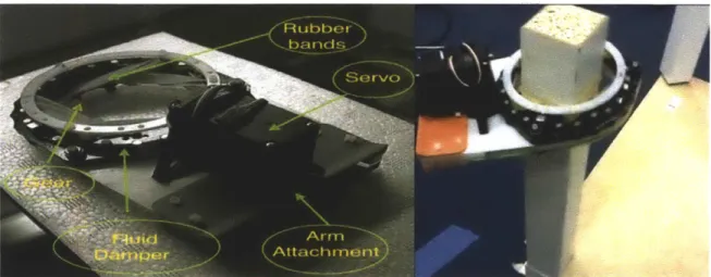
device. The key elements are apparent in the picture, including the drivetrain, the Aluminum frame, and the Kuka attach point (large orange box). On the bottom of the device not shown, are the drive motors, and the bottom ring.
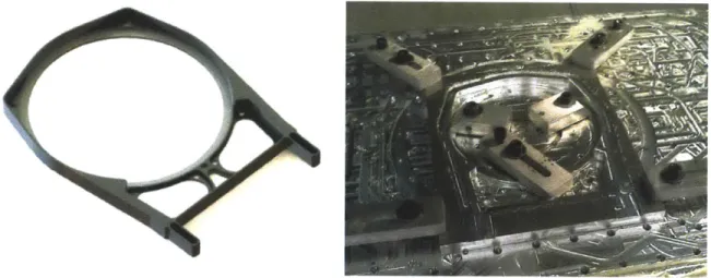
3.2 Designing the Frame
The frame of a house is literally that which everything else is built upon. In this case, the
layers of laser cut plastic as can be seen in figure 3-2. While layered structures can be very
Figure 3-2 Frame of prototype number two. Showing the layered approach taken with the second prototype. This frame was very
heavy, over 120 grams, which is more than four times the weight of the new aluminum frame.
effective, as in the case of composites such as carbon fiber, it is often not the best way to achieve space savings, weight reduction, or precision. The new frame was designed to be CNC milled out of a single block of high performance 7075-T6 aluminum, thereby allowing for more features and taking advantage of the higher specific stiffness of aluminum as compared to plastic.
There is no existing conclusive deterministic method of designing elements that can perform their desired function while optimizing for weight. The best that the designer can do is to use intuition, application of known mechanical principles, and make many iterations. The existence of finite element analysis programs, such as COSMOS in Solidworks, greatly improves this ability. The design process involved first sketching the basic outline of the part - produced
240 587,1$ 2031 3,5520 109254,45W 0 13.54,580 112173C,5760 34 X 0,SW 2 459,07.3 Viek strW.g 5514850D2
Figure 3-3. FEA of the claw's Frame. Showing performance of the frame when subject to simple beam bending. The bright areas are areas of
high stress, and are therefore where the focus of the designer should be in order to ensure that the part doesn't break. In this case the area at the top and the bottom of the left side is shown to have very high stress, in the design process, this led to the creation of the much wider element that can be seen below in figure 4.
This case shows the how the intuitive principles such as symmetry can be used to
improve the design ability. For an object like this which might experience various forces in an
unknown environment, it is safe to assume that it could encounter equal forces from nearly every
different direction. Using symmetry can help to make sure that this is realized, but symmetry
about the right/left axis is easy, while about the top/bottom axis is a little bit more difficult. Since
it is very difficult to machine undercuts which can produce the strong I-beam shape, through the
insight of FEA this same effect was produced by making an the beam in the shape as shown in
PM- I-beam OM
Alternative
Figure 3-4. Cross section of Frame. Showing the design used in order to approximate an I beam in designing the claw's frame
This provides essentially the same performance in bending as an I-beam, but it can be milled easily using traditional milling equipment. The frame was milled on both the front and back out of a single block. The final rendering of the frame and a picture of it clamped in the mill as it is being constructed can be seen in figure 3-5.
Figure 3-5. Claw Frame Detail. Rendering of the Aluminum frame, next to a photograph of the frame under production. This shows the amazing ability of CNC to produce exact copies of out metal.
3.3 Designing the Bearings
From observation as a student in and then as a lab assistant of 2.007 and general
friction caused by improper bearing type. Ball bearings compared to the best frictional bearings
are at least an order of magnitude more efficient due to lack of any energy loss as a result of
mechanical friction. [8] Bering design is important because they are precision elements that
interface between different components and often handle high forces and speeds. At the same
time however sometimes the selection of ball bearings as compared to sliding element bearings is
sometimes unnecessary in terms of cost, stiffness, or complexity.
This was an issue I faced while re-designing the new claw. The old claw used ball
bearings to constrain the spinning rings radially and simple sliding elements in order to constrain
it radially. The new design involved the creation of a large custom thrust bearing that was
designed to cause a minimum of friction, as can be seen in figure 3-6. The rotating ring in the
new design is completely constrained by sliding element bearings, therefore increasing the
efficiency and load capacity of the entire device.
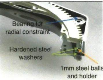
steel balls
and holder
Figure 3-6. Claw bearings detail. Note the two thrust washers made of wear-resistant thin steel stock, the ball container, and the ball bearings
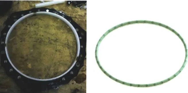
In the claw design there are two rotating rings attached to rubber bands, one of them must have a resistance in order to begin the stretching of the rubber bands, or they will just both spin without engaging the actual part. The functional requirements for such a device are essentially to act as a pure velocity dependent damper. Device based on static friction are not effective at meeting these requirements because stiction force causes friction to be highest when there is no movement, and then decreases to a constant as velocity increases. In order to make an actual damper, some type of fluid that could dissipate the energy was required. Last semester I designed a fluid damper ring that involved the dragging of metal balls through an thick oil by magnets placed on the frame as shown in figure 6. This worked in theory, but in practice the sealing was very difficult. I delicately turned two open faced Acetyl Polymer ring shaped pieces on the lathe in order to create the channel that the oil was going to fit in. However I failed to properly
consider the difficulty that sealing this device would entail and oil constantly leaked from the device.
A
Figure 3-7. Damper Detail. Showing the inside of the old damper design as well as a solid rendering of the new simpler design which uses a
required sealing, it constantly leaked oil. The new design was figured out based on applying the
design principle of simplicity. It was made by simply buying a plastic pipe and bending it into a
donut shape, and then sealing the two ends together with tape. All together this required less than
2% of the sealing area as the previous design and was much easier to manufacture, this change
demonstrated the principles of elegance and design for manufacture described earlier. However
even this design had problems due to the oil interfering with the tape seal. In the version of the claw that was actually finished, this damper has been replaced by a simple sliding frictional
design using a steel ring pulled towards the claw with magnets.
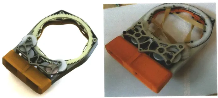
3.5 Modular Design
Since this is still a prototype, I was reluctant to combine too many different features into one single piece. By separating the features onto separate peaces, it allows for disassembly and
improvement of specific pieces in the future. In order to do this I consciously made the interfaces
between various components easy to change and improve in future versions of the claw. Since the aluminum frame element was the most complex and important part to make, I consciously avoided adding specific features such a hole to hold the motor to it. Pieces such as the gear-train
bearing plates, and the robotic arm attachment point are provided by intermediate rapid
prototype- producible pieces, and not the frame itself - so that if these should change only a new piece needs to remade, instead of machining the whole frame again. The design of these pieces can be seen in figure 3-8.
Figure 3-8. Modular assembly rendering. Showing the frame with the replaceable plastic items with specific features (Shown in green), including
the claw attachment piece, and the motor and gear train mounts.
This type of design allows for modularity and adaptation of the design to new
circumstances. For example if the Kuka robot gains a new type of claw mounting point - or if an entirely different robot is used, then an additional connector can simply be 3d - printed. This
greatly improves that utility of the core features of the design. This type of engineering is what
through systems is not as important of a facet of mechanical engineering as it once, it is still an
interesting area of design. In spite of perhaps common sense, I decided to redesign the entire gear
train for the motors. The reason for this choice is to make the whole package fit into a smaller
area while also attempting the challenge of building as efficient as possible of a gear train. Since
every instance where power is passed through one set of gears, over 10% of the energy in the
system is typically lost [8]. Because of this, the most efficient gear trains use spur gear with a
very large difference in relative sizes. Several possible types of power transmission were
investigated. Initially I thought the design of a friction based drive utilizing the large radius of
the central disk combined with the small but fast radius of the motors would be effective, but the
friction interaction proved complicated. Belts were also considered as they have an excellent
efficiency (Approaching 99% under good conditions) [8] but were not used for due to geometric
considerations.
The previous gear system used in the second design iteration involved four sets of spur
gears, with three of those inside the VS-Il servo. The total reduction was about 1:1000, for an
average of 1:5.6 per stage. The new gear train uses two motors to provide twice the power, with
each drive train having only three interacting elements and a total ratio of 1:776, for an average
of 1:9.2 gear reduction per stage. This improvement is mostly due to the fine pitch of the large
ring gear combined with the small 9 tooth spur driving it. Theoretically this new gear train
should be approximately 7% more efficient than the previous one on a ratio basis, due to the
more compact nature, but due to inexact manufacturing processes utilized in its construction it is
3.6.1 Multiple Motors
The second design iteration used only one motor - however I wanted to increase the power while also decreasing the physical bulk of the design. This would be very difficult to accomplish just by using a larger motor without either breaking my principle of symmetry, or the
shape and size requirements. I decided to look into different other options. There are definitely benefits to using several small motors as opposed to one motor including redundancy, form
factor, ease of power-transmission elements gearing (and the possibility of large reductions due to high ratio of big circle to really small circle), and the possibility of less strain on the gear train
due to multiple points of interaction. However they suffer from some significant issues involving efficiency and perhaps complexity. There has been little research (that I can find) on the actual engineering tradeoffs on this approach. The actual benefits of this implementation likely depend on the circumstances. In this case at least it allows for an increase in the power without a
concomitant increase in size, which was the design intent.
3.7 YouBot connector and Electronics
In order to connect the claw fixture to the youBot hand, and use the robot controller for its operation, a controller was developed to provide this interface. The motors needed to
communicate with the robot system so an arduino -based electrical system was designed in order to run the claw. This system provides for a robust method of accurately positioning the claw, as the details of the encoder control are handled by the arduino microprocessor, and the YouBot-arduino interface only involves low bandwidth general instructions.
kind of self-grabbing self-attaching connector. One particularly elegant way to do this is through magnetic connectors like the Apple Mag-safe power adaptor.[11] While this has not actually be designed or built, its construction would aid in the ease of attachment and detachment from the claw, and allow the robot to do this without human intervention.
This is accomplished using an off the shelf Arduino nano microprocessor. The Arduino is programmed in Arduino language which is based on C++ and the interface with the ROS running the youbot is provided through an USB cable and using several existing arduino-ROS
4.1 General Results
The claw fulfilled the primary goals of improved weight, performance and size. The new
claw is adequately able to attach the Table leg to the Lak table as shown in figure 4-1.
Figure 4-1. Attaching Leg. Figure showing the new claw attaching a Lak table leg to the table.
The claw was also adept at picking up additional objects, including smaller objects such as 9-volt
battery due to its smaller bulk. While there are components of the project that are unfinished, the
design works and hopefully will be improved in the near future.
4.2 Grasping characterization
While the previous design just happened to work, this is an unacceptable rational for
Figure 4-2. Showing the model of the interaction between the elastic encircling elements and the object being
gripped. Figure 2. Red arrow shows tension force, Blue shows normal force (On the bottle) and green shows the frictional forces, which combine to create the torque on the object.
The way to analysis this is to use equation 1: the Capstan equation [8] This equation makes a connection between the coefficient of friction, the contact arc, and the effective tension
Equation 1 = Th0Id e
(or torque) that the element provides. As the angle of contact increases, the maximum torque increases exponentially. This means that roughly once the bands are wrapped around sufficiently around the object, the system in fact becomes self-tightening, and will work until either the motor torque is over come, or the encircling bands break. The required angle for self-tightening can be estimated to be when Thold is >> than Tload In terms of rubber bands (p for rubber is
around 1), this condition is met around an angle of pi/2 degrees. This fact that it "just worked" in previous designs is due to the very high degree of forgiveness that the system provides due to the self-tightening behavior exhibited in the capstan equation.
However a more detailed analysis of the performance of different elastic elements and the coefficient of friction between the elements can be inferred from figure 4-2. This graph shows the combined torque factor (Tension inputted divided by tension Output) that increases
Torque applied to object at different encirclement paramaters mu =0 5 mu = 0 75 MU = 1 0 mu = 1 25 mu = 1 5 1 2 3 4 5 6
Relative Ring Rotation (radians)
Figure 4-3. Tension characterization graph - showing the amount of torque provided under different interactions between the elastic members and the object being grasped
This model provides an incredibly wide range of diameters, surface roughness's, number
of rubber bands and due to the self-tightening capstan effect of the rubber pulleys. Since the
coeeficient of friction between the objects depends on a diverse array of factors, including the
objects shape and surface properties, figure 4-3 shows us that for almost any combination of
these factors, a high degree of grasping torque can be provided due to the capstan effect 4W00 350-300 C 0 C 4) 20 E 2O S200, ~15,0 0' 0
The final prototype looks and behaves more robustly than the initial prototype, and it has
twice the power, while being lighter and better looking. The use of high quality engineering
materials, including Aluminum allows 7075 and Acetyl Copolymer plastic gives the device
improved performance characteristics than the previous design. The prototype claw was tested to
grasp and screw in the Lak table leg in four experiments. Each full grasping and operation took an average of around 30 seconds.
Table 4-1 Showing a comparison of the different prototypes
Parameter Protoype 1 Prototype 2 Final Prototype
Weight Unknown 360 grams 226 grams
Bounding Box 12x24x13 10x25x13 4x18x13 cm
Cost $100 (est) $300 (est) $460 (est)
Gear ratio unknown 1:800 1:439
4.4Discussion
Through designing this product, I learned many things not only about analysis of mechanical design, but also about different machining techniques. I also learned many things about design, FEA software and machining by the work done in this project.
4.4.1 Lessons Learned
" The claw concept can deliver on the desired function to screw in objects of different
sizes.
* The claw can deliver the required force and torque for grasping, ungrasping, and rotation of objects.
* Use proper fixtures while machining! I once was turning a complex piece, and it wasn't fixtured correctly, and then it caught on the tool and destroyed itself. * Think out Process plans for complex machining processes before beginning work
on them.
* Servo gear-trains are amazingly designed and efficient for machines that cost under ten dollars.
0 Complicated projects can cause all different kinds of problems that cascade into one
another in order to cause delay in the project. Organization is key in order to mitigate these problems.
4.4.2 Future Work
In the short term, the integration of the claw with the YouBot and extensive autonomous manipulation experiments are required so that a technical paper can be written to discuss the concept, problems, algorithms and challenges involving assembling furniture with Youbots.
things, will want to have access to human tools such as screw-drivers, wrenches, hex drivers, hand-drills, while ideally robots would not need to carry around multiple different claws in order
to use these tools, some device capable of continues spinning would be helpful for these tasks.
The other key aspect of this claw is its ability to handle very delicate objects, the same type of
design that uses the encirclement of objects by elastic elements could be used for all kinds of
Appendix A. Technical drawing of aluminum frame A Works Student on Academic Use On y 2.thu Ranishin 'A
3 %scrsz get(,'ScreenSize');
4 %Ligure('Position',[1 scrsz(4)/2 scrsz(3)/2 scrsz(4)/2])
5 - set(figure, 'color', 'white'); % sets the color to white
6 - hold on
7
8- xlabel('Relative Ring Rotation (radians)')
9 - ylabel('Torque Applied (non-dinensional)')
10 - title('Torque applied to object at differenL encirclement paramaters')
11 - h_xlabel - get(gca,'XLabel');
12 - set(h_xlabel,'FontSize',13);
13 - b__xlabel - get(gca, 'YLabeoli);
14 - set(b_xlabel,'FonLSize',13);
15 - c_xlabel get (gca, TiLe');
16 - set(c_xlabel,'FontSize',13); 17 - axis([O 2*pi 0 4001) 19 - mu = 0.5 20 - mul - 0.75 21 - mu2 - 1.0 22 - mu3 - 1.25 23 - mu4 e 1.5 24
25 - range " 1O:0.01:2*pi)
26 - c ! 4.*exp(mu*range)
27 - ci= 4.*exp(mul*range)
28 - c2=. 4.*exp(mu2*range)
29 - c3- 4.*exp(mu3*range)
30 - c4= 4.*exp(mu4*range)
31 - legend('nu 0.5','nu 0. 75', 'mu =1.0",'mu 1.25','mu 1.5')
32
33
34 - run1 - plot(range,c,'color', [0 1 0J,'LineWidLth',1.0)
35 - run2 = plot(range,cl,'color', [0 0.8 01,'LineWidth',1.0)
36 - run3 - plot(range,c2,'color', [0 0.6 0],'LineWidth',1.0)
37 - run4 - plot(range,c3,'color', [0 0.4 01,'LineWidth',1.0)
38 - runS m plot(range,c4,'coLor', [0 0.2 0),'LinoWidth',1.0)
39 %run6 plot(dataxdatay,'color', [0 0.2 01,'LineWidth',1.0)
40
41 - legend('mu -0.5','mu - 0.75','mu = 1.0','mu 1.25','mu 1.5')
42
43 %seL(hlegend,'FontSize',13);
44 %actualdata degrees [0 80 grams 300 700 100041
[1] Balaguer C. and M. Abderrahim. 2008. "Trends in Robotics and Automation in Construction", in Robotics and Automation in
Construction, Eds. by C. Balaguer and M. Abderrahim. Vienna, Austria: InTech Education and Publishing.
[2] Jones, J.L.; , "Robots at the tipping point: the road to iRobot Roomba," Robotics & Automation Magazine, IEEE , vol.13,
no.1, pp. 76- 78, March 2006 doi: 10.1 109/MRA.2006.1598056
URL: http://ieeexplore.ieee.org-/stamp/stamp.isp?tp=&arnumber=1598056&isnumber=336l1
[3] Heartland Robotics Vision 2012. Heartland Robotics. Accessed May 21 2012 at http://heartlandrobotics.com/vision.html. [3] Pictures from www.ikea.com and www.kuka.com Accessed December 2011
[4] from video "Elastic torque gripper" on http://www.voutube.com/watch?v=NgtBPiiaRJ8 Accessed May 24 2012 [5 ]Quotes on Simplicity. Accessed May 22 2012. http://www.inspireux.com/wp-content/uploads/49.gif
[6] THE IMPORTANCE OF SYMMETRY AND COMPLEXITY IN THE EVALUATION OF COMPLEXITY, INTEREST
AND PLEAS1NGNESS. DAY, HY Psychonomic Science, Vol 10(10), 1968, 339-340.
[7] A third industrial revolution. Accessed May 21 2012 at http://www.economist.com/node/21552901
[81Slocum, Alex. Precision Machine Design
[12] Apple Magnetic Adaptor, US Patent 7311526. Accessed on May 22 2012 at http://patfI.uspto.gov/nelacei/nph-Parser?Sect I =PTO2&Sect2=HITOFF&p 1&u
%2Enetahtml%2FPTO%2Fsearch-bool.html&r=1&f -G&l 50&col AND&d=PTXT&s1 7311526.PN.&OS=PN/7311526&RS=PN/7311526