Philipp Hass *, Falk K. Wittel and Peter Niemz
Generic failure mechanisms in adhesive bonds
Abstract: The failure of adhesive bondlines has beenstudied at the microscopic level via tensile tests. Stable crack propagation could be generated by means of samples with improved geometry, which made in situ observations possible. The interaction of cracks with adhesive bond-lines under various angles to the crack propagation was the focus of this study, as well as the respective loading situations for the adhesives urea formaldehyde (UF), polyurethane (PUR), and polyvinyl acetate (PVAc), which have distinctly different mechanical behaviors. It has been shown how adhesive properties influence the occur-rence of certain failure mechanisms and determine their appearance and order of magnitude. With the observed failure mechanisms, it becomes possible to predict the propagation path of a crack through the specimen.
Keywords: adhesive, bondline, failure mechanism,
spruce wood
*Corresponding author: Philipp Hass, Institute for Building Materials , ETH Zurich, Schafmattstrasse 6, CH-8093 Zurich , Switzerland , e-mail: [email protected]
Falk K. Wittel: Institute for Building Materials , ETH Zurich, CH-8093 Zurich , Switzerland
Peter Niemz: Institute for Building Materials , ETH Zurich, CH-8093 Zurich , Switzerland
Introduction
Cellular failure mechanisms in bulk wood have been the subject of many investigations in the past for various wood species, as well as failure in all anatomical directions, for single as well as mixed-mode loading (Borgin 1971 ; Bodner et al. 1997a,b ; Thuvander and Berglund 2000 ; Tschegg et al. 2001 ; Dill -Langer et al. 2002 ; Reiterer and Sinn 2002 ; Conrad et al. 2003 ; Koponen and Tukiainen 2006 ; Keunecke et al. 2007 ; Vasic and Stanzl -Tschegg 2007 ; Oliveira et al. 2009 ; Stanzl -Tschegg and Navi 2009 ). While studies on solid wood (SW) have been carried out on all scales of length, down to tests on single fibers (Eder et al. 2008 ), knowledge on failure mechanisms of adhe-sive bonds is based mainly on large samples such as the double cantilever beam (Dourado et al. 2010 ; Singh et al. 2010 ; Nicoli et al. 2012 ). Estimates on microscopic failure
mechanisms have resulted mainly from indirect observa-tions like fracture surface investigaobserva-tions (River et al. 1994 ; Simon and Valentin 2000, 2003 ), video image correlation of the sample surface (Niemz et al. 2007 ), or acoustic emis-sions during failure (Suzuki and Schniewind 1987 ).
These surveys focused primarily on fracture mechani-cal properties, ignoring the underlying generic failure mechanism of adhesive bonds. However, it is known that failure is initiated on a small scale by micro defects that interact and join to form cracks that grow and become relevant on a larger scale. Depending on the adhesive type, moisture induced stresses resulting from hindered swell-ing and shrinkage, as well as cracks that develop durswell-ing the curing of an adhesive, induce defects into the bonding (River 2003 ; Frihart 2009 ). However, failure mechanisms and crack evolution in adhesive bonds have not yet been studied for a constant climate. Investigations at the microscopic or mesoscopic scale are therefore essential to develop an understanding of the behavior and failure of wood adhesive connections that are of fundamental importance for modern wood constructions under various loading situations, made with different adhesive systems. In the present study, microscopic failure mechanisms in adhesive bonds, made of systems with differing elas-ticity and curing reactions, were studied. To this aim, the crack propagation (CP) and crack-bondline interaction were observed in situ under mode l loading. In addition to the effect of adhesive properties, the influence of the bondline (BL) orientation on the crack initiation direction was observed.
Material and methods
Sample material and preparation
For the current investigation, a necked sample shape, as used by Dill -Langer et al. (2002) , was preferred over other microtest setups known for SW under mode l (Fr ü hmann et al. 2003 ; Keunecke et al. 2007 ). To increase crack growth stability, the oak wood supports proposed by Dill -Langer et al. (2002) for load transfer into the test section were replaced by aluminum supports bonded by a polyurethane (PUR) adhesive (Figure 1 c). The specifi c characteristics as well as the recom-mended processing conditions of the adhesive system investigated on spruce [ Picea abies (L.) Karst] are summarized in Table 1 .
Wood beams with a length of 500 mm were bonded by applying the three adhesives, each along a third of the total length along the
longitudinal beam direction (Figure 1a). The variation of the wood properties in this direction is low and the two wooden pieces could be bonded simultaneously, which ensured constant press parame-ters for all samples. The applied pressure and the press time were determined for the respective adhesive with the highest requirements (bold print in Table 1). Each pair of adherends was derived from one beam, which had been divided in half, before both parts were bon-ded again. Aft er curing and acclimatization at 20 ° C and 65 % relative humidity (RH), the bonded beams were planed to cross-section di-mensions of 10 × 20 mm 2 (Figure 1b). CP through wood is most unsta-ble under a TR confi guration (i.e., load in tangential [T] and crack growth in radial [R] direction; Bodig and Jayne 1982 ; Gross and Seelig 2007 ). Therefore, this worst case situation was chosen for this inves-tigation to determine the infl uence of the BL. The angle between the load and BL was varied (0 ° , 45 ° , 60 ° , 75 ° , and 90 ° ). From each beam, fi ve sections of 7 mm length were taken from each adhesive region. The overlapping cross-sections of the samples were removed by a sledge microtome GSL 1 (WSL, Birmensdorf, Switzerland) to allow
Adhesive Description and application a
Amount (g m -2 ) b Open time (min) a Press time (min) a Pressure (MPa) a Solid
content ( % ) a MOE (MPa) c
PUR 1K-PUR for structural wood products 200 40 100 0.7 100 1190
PVAc Adhesive dispersion for universal application in timber industry (D3)
200 8 10 Minimum
0.25
50 – 52 530
UF Cold-setting adhesive powder (EN 12765 C3) containing hardener
200 20 480 Minimum
0.25
60 3000
Table 1 Adhesive systems, properties, and processing conditions.
a Manufacturers ’ declarations for 20 ° C. b Within range of manufacturers ’ recommendations. c Obtained from own compression tests on adhesive cubes for UF and tensile tests on adhesive films for PUR and PVAc, respectively.
PU UF PV R40 10 50 5 α 16 a b c d
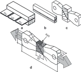
Figure 1 Sample preparation procedure: (a) bonding of beams with three different adhesives; (b) planing and aligning the BL; (c) joining of wood and aluminum supports; (d) finished specimen with dimensions (mm). Arrows indicate the load direction, and α indicates the angle between load direction and the BL, here 45 ° ; darker surfaces represent different preparation techniques: A: belt grinder, B: microtome.
for microscopic in situ observation (Figure 1d). In total, 225 samp-les with adhesive BLs were tested (3 adhesives × 3 beams × 5 angsamp-les × 5 repetitions). A radial crack initiation notch was introduced on one sample side either from pith to bark (in-radial, IR) or in the opposite direction (contra-radial, CR). As reference, 15 unbonded specimens from three diff erent beams were tested. The samples were loaded in a Deben Microtest microstage via alignment pins, which only allowed for rotation around their axis as the crack propagated. This way, the maximum load was always at the crack tip and momentum infl uen-ces were minimized. In situ observations were made with a stereo-mi-croscope at a frequency of 5 Hz at a loading rate of 0.1 mm min -1 . Note that imaging was triggered at a load of 10 N and that measured force-displacement curves were used for synchronization with the images.
Analysis
The acquired images were evaluated fi rst qualitatively, focusing on the diff erent adhesives. For each beam, a direct comparison between adhesives could be achieved for IR and CR crack growth, as well as between the adhesives themselves. This information was then used to fi nd diff erences between the BL-load angles. As such samples are too small to reliably measure fracture mechanical properties, the load-displacement data were considered only as an indicator.
Results and discussion
Solid wood
In Figure 2 I, the typical failure mechanisms for mode I loading in the T-direction are given along with the respec-tive load-displacement curve (Figure 2Ib).
At the beginning of all load-displacement curves, adjustment processes of the microstage dominate. Note that all images of different failure situations are aligned in the same way concerning the load direction. The cracks advanced rather straight through the samples. As visible in the load-displacement curve (Figure 2Ib), samples failed relatively abruptly, with a distinct precracking (Figure 2Ic) in the latewood (LW) zone, often with a parallel offset to
the main crack. Intercellular fracture could be observed in the LW, while intracellular fracture dominated in early-wood (EW). This supports the known failure mechanisms for solid spruce wood under the load situation applied in this article (Thuvander and Berglund 2000 ; Dill -Langer et al. 2002 ; Conrad et al. 2003 ). Because no influence of the crack initiation direction was observed for any of the bonded samples, this factor was disregarded in further discussion.
Bonded samples
Three distinct orientations were found to capture typical failure situations: BL parallel (0 ° ) and perpendicular (90 ° ) to the loading direction as well as angles in between (45 ° – 75 ° ). In the following, samples from identical beams are juxtaposed for each of these cases to highlight the dif-ferences between the adhesive systems. Existing BLs in the images are highlighted by brackets. Because PUR and polyvinyl acetate (PVAc) showed quite similar behaviors regarding the CP, often, only one representative sample is presented. Additionally, the influence of predamages at BLs and the observations of adhesive layer delamination are discussed before the quantitative subsumption of the results.
Load direction and BL at 0
°
The BL has different properties than the adjacent wood and hence can be compared with an additional growth ring border. Because this layer was orientated in the T-direc-tion, the final failure pattern showed features similar to those of SW: the crack could cross the BL in a more or less straight line (Figure 2II) or it could be deflected at the BL, leading to roll-shear failure along the BL or along a growth ring border, if it is adjacent to the BL (Figure 2III). This roll-shear failure is also typical for SW, if shifted precracks form ahead of the main crack, leading to failure in the EW zone along growth ring borders. For the three adhesives, CP and crack-BL interactions differed, as described in the following.
In urea formaldehyde (UF)-bonded samples, the brittle BL actually acted as an additional LW zone, where precracks originated, leading to preferred paths for the main crack (Figure 2IIa – c). Former studies (Hass et al. 2011) revealed a distinct crack pattern in the adhesive layer due to the restrained shrinkage in UF BLs during harden-ing. It can therefore be assumed that the relevant precrack in the BL emanated from the curing of the adhesive.
Load direction 60 40 20 a a d e c a b c d f e g g f b I II III b c a c Load (N) Displacement (mm) Displacement (mm) Load (N) Displacement (mm) Load (N) 0.2 20 40 60 UF PUR a d e b c f a d e b f c 0.4 0 0 0 20 40 60 80 0.5 1.0 1.5 0 0 0 0.2 0.4
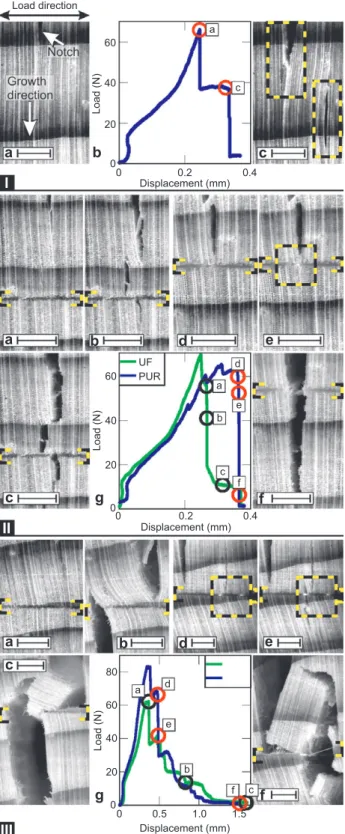
Figure 2 CP through spruce wood. All scales correspond to 1 mm. The plots show the load-displacement diagrams. (I ) SW with IR CP. Maximum loading (a) and postpeak behavior (c). (II) BL at 0 ° with CR CP through UF (a – c) and PUR (d – f) without deflection at the BL; the box in panel (e) shows stress whitening in adhesive layer. (III) BL at 0 ° with CR CP through UF (a – d) and IR CP through PUR (e – g) with deflection at the BL; boxes highlight stress whitening and adhesive fingers.
In PUR or PVAc BLs, precracks were not detectable because these systems are softer (see Table 1). In most cases, the crack stopped at the BL before penetrating it (Figure 2IId – f). In many cases, the BLs even stayed intact while the crack continued below it, either directly or via a precrack, which appeared in an LW zone across the BL, grew upwards into the BL and downwards through the sample (Figure 2IIId – f). Further in the failure pro-gress, the adhesive layer dissipated energy, which became visible via stress whitening, a common change in translucency of polymeric materials (Figures 2IIe and 2IIId – e).
If a precrack tangentially shifted with respect to the main crack at the BL, the coalescing of the cracks resulted in a roll-shear failure pattern. Here, again, the adhesives showed different reactions. In UF, the same behavior as for SW was observed: the EW next to the growth ring border or in the BL was sheared off with some fiber bridg-ing (Figure 2IIIa – c). In PUR, the failure path followed the BL, while distinct adhesive fingers formed (Figure 2IIId – f). However, the quantitative differences are small (Figure 2IIIg).
Load direction and BL at 45
° – 75 °
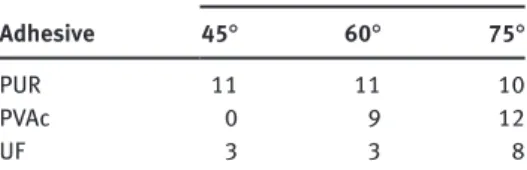
The influence of the BL grew with increasing angle b e-tween BL and load direction or decreasing angle bee-tween crack growth direction and BL. Consequently, the prob-ability of crack deflection at the BL increased for higher angles. Distinct differences between the adhesives could be observed here, as a critical angle seemed to exist at which a crack deflection at the BL became more probable or, in other terms, energetically more favorable than BL penetration. For PUR, most cracks had already deflected at the BL for load-BL angles of 45 ° , while for PVAc, the number of deflections increased for angles above 60 ° and only at 75 ° did at least half of the samples show a deflec-tion for UF (Table 2 ).
Adhesive
Number of samples with crack deflection at the BL
45 ° 60 ° 75 °
PUR 11 11 10
PVAc 0 9 12
UF 3 3 8
Table 2 Number of samples showing crack deflection at the BL as a function of adhesive system and angle between load direction and the BL (45 ° – 75 ° ).
As already observed for the 0 ° samples, UF BLs acted as crack starters, where precracks originated, enhancing the CP through the sample. In cases where no precracks could be observed, CP across the BL was so fast that the actual intersection of the BL and the crack could not be imaged. Only at angles larger than 75 ° were precracks also detectable in other regions of the BL other than the pure adhesive layer. If the crack was deflected at the BL, then the crack propagated parallel to the BL until it reached the next growth ring border or a crack in the BL (Figure 3 Ia – c), where the crack could cross into the other adher-end and further propagate radially through it. Of all the studied adhesive systems, UF had the highest modulus of elasticity (MOE) contrast compared with spruce, perpen-dicular to the grain. As a result, shear failure of tracheids was quite common, leading to crack deflection along the BL. To summarize, failure within UF-bonded samples was brittle, without a decelerating influence of the BL on the CP. Even though the crack deviated along the BL, it behaved similar to a crack deflected along a growth ring border, exhibiting basically identical microscopic failure mechanisms.
In PUR and PVAc BLs, the crack growth could be slowed down or even stopped by the BL, comparable with the situation at 0 ° . When deflected, the crack propagated parallel to the BL at least until the next growth ring border or until a defect in the BL was reached (Figure 3Id – f). In PUR, such defects appeared as stretched pores, and their extensions determined whether the crack crossed the BL into the other adherend. Even a continuation of the deflec-tion parallel to the BL – in the unnotched adherend or a recrossing of the crack into the notched adherend – could be observed. The crossing of the crack into the unnotched adherend was accompanied by the formation of precracks in both adherends around the BL, stress whitening in the BL, and the formation of an adhesive bridge. A more precise description of this behavior will be given later.
The growth ring borders were preferred zones for crack crossings from one adherend into the other for several reasons. First, differences in mechanical proper-ties lead to stress concentrations. In addition, residual stresses resulted from differential swelling of EW and LW during the absorption or desorption of water from the adhesive. The different reactions of different BLs towards moisture were recently discussed by Frihart (2009) , who showed the ability of adhesives to distribute residual stresses arising from the different swelling behaviors between wood and adhesives. Although the focus was on cured BLs, it seems reasonable to assume that these reactions already occurred during the bond formation, as the swollen wood was hindered from shrinking back
to its original dimensions after the adhesive had solidi-fied. The amount of water introduced depended on the solid content and the curing chemism (see Table 1 or, e.g., Dunky and Niemz 2002 ). The UF resin and PVAc intro-duced water into the system, while PUR withdrew some water from the wood for curing. It can be assumed that this led to low residual stresses for PUR and PVAc due to the small dimensional changes for PUR and the low MOE and yield stress of PVAc when compared with UF, which has a high MOE and additionally causes high moisture-induced dimensional changes of the wood substrate.
Rate effects could be observed for PVAc, where cracks propagating at high speeds in the regime above the criti-cal length for stable growth interacted with the BL. In this case, viscoelastic PVAc failed instantaneously. Slow, stable cracks, however, impeded and even stopped at the BL, as there was enough time for plastic stress release and crack tip blunting. The high deformability of the PVAc became visible in an observable relative movement of the two adherends, once the crack entered the BL. Although the final failure pattern suggests that cracks deviated only at angles of 60 ° or more, the in situ observations revealed that for 45 ° , cracks started to grow along the BL in com-bination with the development of stress whitening and elongation of the adhesive layer. However, with increas-ing load, the adhesive layer failed and the crack crossed straight into the other adherend without visible deviation in the final failure pattern.
Load direction and BL at 90
°
At an angle of 90 ° , a deflection of the crack along the BL proved most probable. However, it was also observed that cracks stayed within the wood for various reasons. One constellation was found when the R-direction of the adher-ends was not aligned completely perpendicular to the load direction. Here, the crack could leave its path along the BL and propagate through the wood in the R-direction (Figure 3IId). Another scenario was the crack deviation through an adherend adjacent to the BL. In these cases, the typical failure behavior for SW with unstable CP and precracks in the LW zones could not be observed. Appar-ently, the adhesive still had an effect at some distance from the actual BL. This zone of influence adds another region to the known BL composition and its extent; furthermore, its dependence on the BL properties should be addressed in future investigations.
As cracks take the path of least resistance, they changed from one adherend to the other following the energetically favorable way. Due to differing adhesive
a a e f g c b d f b d c e II b d a b e f UF PUR PVRc e c UF PUR Load (N) 0 0 0.2 0.4 0.6 Displacement (mm) 20 40 60 80 Load (N) 0 0 0.5 Displacement (mm) 1.0 1.5 20 40 60 80 I
Figure 3 (I) BL at 75 ° with IR CP through UF (a – c) and PUR (d – g); panels (a) and (f) show final stages of failure. Boxes highlight the deflected crack path until the crack crosses the BL at the growth ring border. (II) BL at 90 ° . (a – b) IR CP through UF (box: precrack in the BL causing the crack to cross); (d) CR propagating crack leaving PUR BL along the R-direction (box: start of deviation); (e – f) IR CP through PVAc (box: adhesive bridging). All scales correspond to 1 mm.
properties, the overall crack path along the adhesive inter-phase was different for the various adhesives.
The behavior of UF-bonded samples was similar to that of SW, as precracks mostly appeared in the BL next to LW zones ahead of the main crack (Figure 3IIa – b). Due to its high stiffness, the UF BL transferred stress directly between both adherends. This means that weak points at some distance from the BL could also form precracks, leading to a failure evolution through SW.
The more flexible PUR and PVAc BLs were also able to deform and dissipate energy. Therefore, precracks were rarely observed distant from the BL. Cracks in wood could be stabilized when they stayed close to the BL, resulting in stable CP even without crossing the BL, as was mentioned before. However, once a crack entered the zone between the wood-adhesive interphase and adhesive layer, the majority of cracks followed this interface. It was possible to allocate this failure position due to the formation of adhesive bridges, which seemed to consist mainly of the entire adhesive layer. For further CP, the growth ring borders and their alignment played an important role: (1) When they were alternating (LW zone of one adherend opposite an EW zone of the other), precracks appeared in the BL next to the EW zone because the low tensile strength of EW led to failure. The crack continued along the BL until it reached the next LW zone, where the precracking and side shifting were repeated (Figure 3IIe – f). (2) When the growth ring borders of both adherends faced each other, the adhesive was strained, as evidenced by stress whitening next to the LW zones. In the absence of relevant BL defects, the samples failed as in SW.
Additional observations
There are several sources for predamaging in the BL region. First, the BLs themselves are damaged as a result of their restrained curing (Hass et al. 2011 ), as described for UF above. Predamage may also originate from the bonding process, when rigid LW zones are pressed into soft EW zones (Figure 4 Ia); EW deformations and even fractures can be observed (Figure 4Ic – d). It is possible that
I II III b a c f e d a b c d e b a c d e f g h f
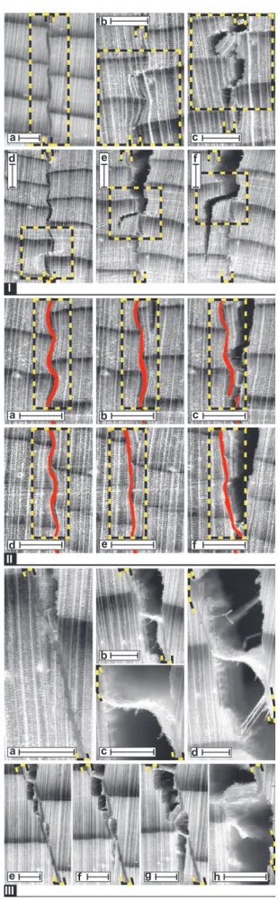
Figure 4 (I) Different formations of predamage: (a) Elastic deforma-tions without visible precracks in adherends and no influence on CP. (b – c) Predamage at LW-EW contact zones acting as precracks for the CP along the BL. (d – f) Predamage at LW-EW contact zones leading the crack away from the BL. Boxes highlight corresponding fracture zones. (II) BL deformations in UF (a – c) and PVAc (d – f) at dif-ferent loading stages. Boxes highlight corresponding positions. (III) Development of adhesive bridges and fingers in PUR (a – f) and PVAc (g – k). All scales correspond to 1 mm.
uneven sample surfaces prior to bonding (planing) led to pressure peaks, which forced the LW into the EW.
Small deformations (Figure 4Ia) did not change the crack path. High deformations or even fractures, however, functioned as precracks, which enhanced the CP (Figure 4Ib – c). They even could direct the crack deeper into the wood, causing the crack to leave the influence zone of the BL and cause instable crack growth through the wood of the adherend (Figure 4Id – f).
Deformations like elastic compression could even be desirable in case of increased failure strain because the compression had to be reversed before the tensile stresses arose. For PUR and PVAc, the adhesive layer even remained straight after failure, showing the high amount of plastic deformation of the adhesive layer (Figure 4IId – f). UF BLs, however, “ froze ” the wood cells in their compressed state. The stress was transferred directly across the BL and the cells were hindered from relieving the compression. The BL only slightly aligned perpendicular to the load direc-tion during stress and fell back to its compressed posidirec-tion after the crack passed (Figure 4IIa – c).
As mentioned previously, the rather flexible PUR and PVAc could also peel off, forming adhesive bridges and fingers. With their high failure strain, they were able to stabilize and slow down the CP (Figure 4III). These bridges consisted mainly of the adhesive layer, with additional thin adhesive fingers (for PUR, see Figure 4IIIa – d; for PVAc, see Figure 4IIIe – h), which connected the two adherends. For UF, the opposite was the case, as wood delaminated from the BL. The only possibility for the formation of stabilizing bridges was given by the wood itself via fiber bridging.
Quantitative estimates
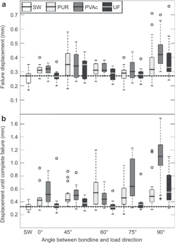
For technical reasons, tensile strength and failure dis-placement were chosen for comparison. Additionally, displacement until the applied load dropped below 8 N was taken as a criterion for complete failure. The tensile strength and failure strain depended primarily on the wood itself, mainly because they were reached before the crack interacted with the BL. Accordingly, values for the different adhesives and load angles were within the range of SW (Figure 5 a). The displacement until complete failure confirmed earlier observations; namely, the higher the angle is between BL and load direction, the higher the influence of the adhesive (Figure 5b). For angles < 60 ° , the differences between the three adhesives were not sig-nificant, but a trend was visible, with PVAc having the highest failure displacement, followed by PUR and UF.
0.7 SW PUR PVAc UF 0.6 0.5 0.4 0.3 Failure displacement (mm)
Displacement until complete failure (mm)
0.2 0.1 1.6 1.4 1.2 1.0 0.8 0.6 0.4 0.2 a b SW 0° 45° 60° 75° 90°
Angle between bondline and load direction
Figure 5 Failure displacement (a) and displacement until complete failure (b) for bonded spruce wood and SW under mode I (TR con-figuration) as a function of adhesive systems and angle between the BL and load direction, compared with SW.
At angles > 75 ° , the high flexibility of PVAc became more evident and the displacement order was the same as that for angles < 60 ° . Although the expected order in flexibil-ity was kept – PVAc, PUR, UF, and SW – the high differ-ences in the adhesives ’ MOE (Table 1) suggested a more pronounced differentiation.
Conclusions
Depending on adhesive properties and BL orientation, CP through a bonded sample can differ considerably from that of SW. Brittle UF BLs provide new crack starters begin-ning with a curing damage. The CP can be accelerated and shows the same unstable behavior as through SW. BLs of PUR and PVAc can slow down and stabilize the CP compared with SW by forming adhesive bridges between two adherends. They can moderate property differences between tissue types. The adhesive layer itself is able to
deform plastically, leading to blunting of the crack tip. Growth ring borders are always preferred positions for a crack to cross between adherends. With suitable adhe-sives, the failure path and also the duration of bonding until final failure can be increased by stable deflection of the crack along the interphase. CP is hindered most effec-tively when the crack is kept inside the zone of influence of the BL as long as possible. This is in contrast to the tra-ditional belief that the failure of a bonding should occur in the wood part, away from the BL (wood failure). Although this type of failure ensures the integrity of the BL, the posi-tive effects of stable CP along highly dissipaposi-tive adhesive layers are disregarded, as brittle wood failure is promoted.
The observations in this article are a good basis for future failure predictions. In future studies, the effects of precompactions on the failure process, as well as the
extent of the zone of influence of the BL for different adhesives, should be addressed. Additionally, the failure mechanisms of different wood species, including hard-woods, are still waiting for in-depth evaluation.
Acknowledgements : The authors acknowledge the sup
-port under SNF grant 200020_132662 ( “ Micro-Mec hanics of Bondline Failure ” ) and Dr. Holger G ä rtner from the WSL for help with microtome preparations and also thank the companies Purbond and Geistlich Ligamenta for provi-sion of the adhesives.
Received December 14, 2011 ; accepted August 10, 2012; previously published online September 4, 2012
References
Bodner, J., Schlag, M.G., Gr ü ll, G. (1997a) Fracture initiation and progress in wood specimens stressed in tension. Part I. Clear wood specimens stressed parallel to the grain. Holzforschung 51:479 – 484.
Bodner, J., Schlag, M.G., Gr ü ll, G. (1997b) Fracture initiation and progress in wood specimens stressed in tension. Part II. Compression wood specimens stressed parallel to the grain. Holzforschung 51:571 – 576.
Bodig, J., Jayne, B.A. Mechanics of Wood and Wood Composites. Van Nostrand Reinhold, Malabar, FL, 1982.
Borgin, K. (1971) The cohesive failure of wood studied with the scanning electron microscope. J. Microsc. Oxford 94(Pt 1):1 – 11. Conrad, M.P.C., Smith, G.D., Fernlund, G. (2003) Fracture of solid
wood: a review of structure and properties at different length scales. Wood Fiber Sci. 35:570 – 584.
Dill-Langer, G., L ü tze, S., Aicher, S. (2002) Microfracture in wood monitored by confocal laser scanning microscopy. Wood Sci. Technol. 36:487 – 499.
Dourado, N.M.M., de Moura, M.F.S.F., Morais, J.J.L., Silva, M.A.L. (2010) Estimate of resistance-curve in wood through the double cantilever beam test. Holzforschung 64:119 – 126. Dunky, M., Niemz, N. Holzwerkstoffe und Leime. Springer-Verlag,
Berlin, Germany, 2002.
Eder, M., Stanzl-Tschegg, S., Burgert, I. (2008) The fracture behaviour of single wood fibres is governed by geometrical constraints: in situ ESEM studies on three fibre types. Wood Sci. Technol. 42:679 – 689.
Frihart, C.R. (2009) Adhesive groups and how they relate to the durability of bonded wood. J. Adhes. Sci. Technol. 23:601 – 617. Fr ü hmann, K., Burgert, I., Stanzl-Tschegg, S.E., Tschegg, E.K.
(2003) Mode I fracture behaviour on the growth ring scale and cellular level of spruce ( Picea abies [L.] Karst.) and beech ( Fagus sylvatica L.) loaded in the TR crack propagation system. Holzforschung 57:653 – 660.
Gross, D., Seelig, T. Bruchmechanik. 4th edition. Springer Verlag, Berlin, Germany, 2007.
Hass, P., Wittel, F.K., Mendoza, M., Stampanoni, M., Herrmann, H.J., Niemz, P. (2011) Adhesive penetration in Beech wood: experiments. Wood Sci. Technol. 46:243 – 256.
Keunecke, D., Stanzl-Tschegg, S., Niemz, P. (2007) Fracture characterisation of yew ( Taxus baccata L.) and spruce ( Picea abies [L.] Karst.) in the radial-tangential and tangential-radial crack propagation system by a micro wedge splitting test. Holzforschung 61:
582 – 588.
Koponen, S., Tukiainen, P. (2006) Fracture behaviour and cutting of small wood specimens in RT-direction. In: Fracture of Nano and Engineering Materials and Structures. Proceedings of the 16th European Conference of Fracture, Alexandroupolis, Greece, July 3 – 7, 2006. Ed. Gdoutos, E.E. Springer, the Netherlands, pp. 1203 – 1204.
Nicoli, E., Dillard, D.A., Frazier, C.E., Zink-Sharp, A. (2012) Charac-terization of mixed-mode I/II fracture properties of adhesively bonded yellow-poplar by a dual actuator test frame instrument. Holzforschung 66:623 – 631.
Niemz, P., Wyss, M., Fuhr, M. (2007) Untersuchungen zum Versagensmechanismus in der Klebfuge bei Zugscherb-elastung. Holztechnologie 48:1 – 5.
Oliveira, J.M.Q., de Moura, M.F.S.F., Morais, J.J.L. (2009) Application of the end loaded split and single-leg bending tests to the mixed-mode fracture characterization of wood. Holzforschung 63:597 – 602.
Reiterer, A., Sinn, G. (2002) Fracture behaviour of modified spruce wood: a study using linear and non linear fracture mechanics. Holzforschung 56:191 – 198.
River, B.H. (2003) Fracture of adhesive-bonded wood joints. In: Handbook of Adhesive Technology. 2nd edition, Revised and Expanded. Eds. Pizzi, A., Mittal, K.L. Marcel Dekker, New York, NY, Chapter 15, covers pages 327–352.
River, B., Ebewele, R., Myers, G. (1994) Failure mechanisms in wood joints bonded with urea-formaldehyde adhesives. Eur. J. Wood Prod. 52:179 – 184.
Simon, F., Valentin, G. (2000) Damage and fracture of wood adhesive bonded joints under shear and opening loading. In: European Structural Integrity Society (Vol. 27) – Fracture of Polymers, Composites and Adhesives. Eds. Williams, J.G., Pavan, A. Elsevier Science Bv., Amsterdam, the Netherlands, pp. 285 – 296.
Simon, F., Valentin, G. (2003) Cohesive failure characterisation of wood adhesive joints loaded in shear. In: European Structural Integrity Society (Vol. 32) – Fracture of Polymers, Composites and Adhesives Il. Eds. Blackman, B.R.K., Pavan, A., Williams, J.G. Elsevier Science Bv., Amsterdam, the Netherlands, pp. 305 – 316.
Singh, H.K., Chakraborty, A., Frazier, C.E., Dillard, D.A. (2010) Mixed mode fracture testing of adhesively bonded wood specimens using a dual actuator load frame. Holzforschung 64:353 – 361.
Stanzl-Tschegg, S.E., Navi, P. (2009) Fracture behaviour of wood and its composites. A review COST Action E35 2004 – 2008: wood machining – micromechanics and fracture. Holzforschung 63:139 – 149.
Suzuki, M., Schniewind, A.P. (1987) Relationship between fracture toughness and acoustic emission during cleavage failure in adhesive joints. Wood Sci. Technol. 21:121 – 130.
Thuvander, F., Berglund, L.A. (2000) In situ observations of fracture mechanisms for radial cracks in wood. J. Mater. Sci. 35: 6277 – 6283.
Tschegg, E.K., Fr ü hmann, K., Stanzl-Tschegg, S.E. (2001) Damage and fracture mechanisms during mode I and III loading of wood. Holzforschung 55:525 – 533.
Vasic, S., Stanzl-Tschegg, S. (2007) Experimental and numerical investigation of wood fracture mechanisms at different humidity levels. Holzforschung 61:367 – 374.