DOI: 10.1007/s10922-005-9014-5
Automated Pattern-Based Service Deployment
in Programmable Networks
Daniela Brauckhoff,1,2 Matthias Bossardt,1and Bernhard Plattner1
Published online: 13 March 2006
This paper presents a flexible service deployment architecture for the automated, on-demand deployment of distributed services in programmable networks. The novelty of our approach is (a) the customization of the deployment protocol by utilizing modu-lar building blocks, namely navigation patterns, aggregation patterns, and capability functions, and (b) the definition of a corresponding service descriptor. A customizable deployment protocol has several important advantages: It supports a multitude of ser-vices, and it allows for an ad hoc optimization of the protocol according to the specific needs of a service and the current network conditions. Moreover, our architecture pro-vides an environment for studying new patterns which aim at reducing deployment latency and bandwidth for certain services. We demonstrate how the developed archi-tecture can be used to setup a virtual private network, and we present measurements conducted with our prototype in the PlanetLab test network. Furthermore, a comparison of a distributed pattern with a centralized pattern illustrates the performance trade-off for different deployment strategies.
KEY WORDS: service deployment; service description; on-demand service deploy-ment; resource discovery.
1. INTRODUCTION
In the last years, numerous distributed network services which can be deployed dynamically, such as firewalls, virtual private networks, video scaling, and load balancing have been proposed by the research community. Such services require the installation of service logic on multiple routers at specific locations within the network. For instance, a virtual private network requires the installation of an IPSec gateway on exactly one node within each of the VPN domains. Addition-ally, the node which is selected to run the IPSec gateway must provide resources such as bandwidth, CPU power, and memory space to operate the service. Current
1Computer Engineering and Networks Laboratory, (TIK), ETH Zurich, Zurich, Switzerland. 2To whom correspondence should be addressed at Computer Engineering and Networks Laboratory,
(TIK), ETH Zurich, Zurich, Switzerland; Email: [email protected]. 81
practice is to deploy distributed services manually. However, manual deployment is time consuming and error-prone. Moreover, since complexity increases with network size, manual deployment is not suited for large-scale networks. A better solution is to automate the service deployment process. The most challenging part in the service deployment process is the identification of nodes which provide the necessary resources to deploy a service. Several approaches target resource discovery in programmable networks. In [1], the formal description of a hierar-chical deployment mechanism based on the gather–compute–scatter algorithm is presented. This work concentrates on developing service deployment algorithms, but does not provide an implementation of a deployment protocol which applies the proposed algorithms. In [2], a network control software is introduced which accepts demands from applications to discover available processing resources. With this approach, each node periodically broadcasts information about its avail-able resources using the OSPF protocol.
In this paper, we present a service deployment architecture which applies on-demand resource discovery. That is, node resources are only queried when a service is about to be deployed within the network. We argue that in large networks which potentially support a broad range of services, continuous collection of node status data is inefficient. This is due to the fact that for a specific deployment operation (a) only a subset of all nodes needs to be queried, and (b) only a subset of all node status data is required. Moreover, collecting node status data on-demand guarantees that the collected data is always up-to-date. However, in order to keep service setup times short, on-demand resource discovery algorithms must be customized to the requirements of the service that is to be deployed. For instance, to deploy a VPN service only nodes within one of the domains to be connected by the VPN need to be queried. In contrast, for the deployment of a firewall nodes at the network border of the secured domain need to be queried.
Hence, we suggest a customizable service deployment protocol that is con-structed from exchangeable protocol building blocks, namely patterns. The proto-col is based on the concept of navigation patterns and aggregators introduced in [3]. We further modularize the protocol functionality by introducing a third build-ing block, called capability function. Moreover, we define a correspondbuild-ing service descriptor, and conduct measurements with a prototype of the service deployment architecture on the PlanetLab platform. This paper is organized as follows: Sec-tion 2 aims at familiarizing the reader with the concepts of pattern-based service deployment. In Section 3, we present a detailed description of our new approach to service deployment. The implemented service deployment prototype is presented in Section 4. Section 5 describes how our prototype can be applied to deploy a virtual private network. Section 6 presents an evaluation of our prototype based on measurements conducted in the PlanetLab [4] test environment. In Section 7, we draw our conclusions and give an outlook on future work.
2. PATTERN-BASED SERVICE DEPLOYMENT 2.1. Service Deployment Steps
Service deployment is an important phase of service management. We define service deployment as a process consisting of the actions necessary to set up services in computer networks. The deployment process aims at fulfilling the expectations of service users, while efficiently using network resources provided by the network manager.
In programmable networks, deployment and configuration of services can be split into two levels, which are [5]
• The network level where nodes that are able to run service components
are identified.
• The node level where service logic is installed and configured on nodes.
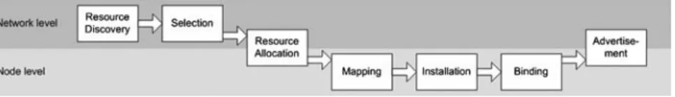
The service deployment process is initiated by the service provider using a service description that specifies the desired characteristics of the service. It ends when the service is successfully installed and configured in the network. Service deployment proceeds in seven subsequent steps assigned to the two levels as shown in Fig.1. The service deployment architecture proposed in this paper targets the network level. Hence, in the following list, the three node level steps are summarized in one item.
• In the resource discovery step, the network is explored to find nodes on
which service components can be installed and executed. Criteria for the evaluation of nodes are specified by the service provider and can be based on a Service Level Agreement (SLA) with the network user.
• In the selection step, relevant information gathered during the previous
step is analyzed. The result of this step is a selection of nodes to run service components.
• In the resource allocation step, network resources (e.g., link bandwidth)
and node resources (e.g., communication ports, memory, and CPU cycles) are allocated. Furthermore, node-level deployment is triggered on these nodes.
• In the next three steps (mapping, installation, and binding) node level
service deployment is performed. That is, service logic is selected and installed on the identified nodes.
• The advertisement step informs whether service deployment was
suc-cessful. If so, it terminates both node and network level deployment by returning information to access the deployed service for further manage-ment operations.
2.2. Patterns for Service Deployment
Patterns for network management are introduced in [6, 7] and applied to network monitoring. The authors introduce the concept of navigation patterns, which describe the flow of control during execution of a distributed operation. This allows the separation of the semantics of a particular management operation, implemented by aggregators, from the control of flow of the operation.
In [8], this pattern-based approach was extended to match the require-ments of service deployment. That is, in addition to the management operations implemented by the echo pattern introduced in [7], service deployment operations require two more phases: (a) triggering the installation of service components on specific nodes, and (b) returning the status of the deployment operation. The authors introduce and simulate navigation patterns and associated aggregators for different service classes. The classification of services with similar deployment requirements into service classes is introduced in [1].
Our approach takes upon the idea of composing service specific deployment protocols from reusable protocol building blocks, namely patterns. We introduce a new pattern class, called capability function, to further modularize the complex service deployment functionality. We define the following three pattern classes, and use them as building blocks to construct service class specific deployment protocols.
The navigation pattern class defines algorithms to visit a set of nodes from which deployment related information is to be collected. Navigation patterns are represented as finite-state-machines (FSM), where messages carrying a mobile state are sent among nodes to trigger state changes. On entering a new state, aggregation functions—defined by an associated aggregation pattern—are exe-cuted. An example for a navigation pattern is an algorithm that floods all nodes within a dedicated domain.
The capability function class defines the information to be collected from nodes. Capability functions evaluate the suitability of a node according to the specified node capabilities, and compute a score for each node. An example is a capability function that determines the current load of a visited node, and marks the node as suitable—a score of one is returned—in case the load is smaller than a specified maximum value.
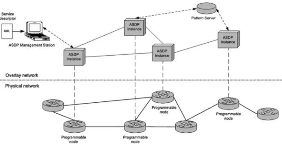
Fig. 2. Network view of the service deployment framework.
The aggregation pattern class defines algorithms to summarize the collected information. Aggregation patterns are executed when a new navigation pattern state is entered. Hence, they must define all aggregation functions that are specified in the FSM of the associated navigation pattern. Moreover, aggregation patterns combine the scores of different nodes generated by capability functions. Thus, the aggregation pattern must know how to interpret these scores. An example for an aggregation pattern is an algorithm that aggregates information in a way that only the node with the highest score is selected.
3. SYSTEM ARCHITECTURE 3.1. Network Infrastructure
In our view, a managed network consists of programmable and conventional nodes. We further assume that all programmable nodes are potential candidates for running service components of a distributed service (see Fig.2). An instance of the automated service deployment protocol daemon (ASDPD) runs ideally on all programmable nodes within the managed network. Moreover, we assume that all nodes that run an ASDPD instance participate in an overlay network, which allows for sending of messages between ASDPD instances. Therefore, the overlay network is required to determine for each ASDPD node: (i) all its programmable neighbor nodes; and (ii) the next hop towards a given network domain or multicast tree.
Each ASDPD instance is equipped with a set of default protocol building blocks. Additionally, the infrastructure supports the download of newly developed protocol blocks from a trusted pattern server. This simple mechanism makes the introduction of new deployment patterns convenient.
Fig . 3. Netw ork le v el service description format X ML schema.
On a separate host, usually controlled by the network manager, runs the ASDP management station. The management station provides the user interface, i.e. means for initiating a service deployment request, selecting nodes on which service components are to be deployed (e.g., if more than one suitable node was identified by the ASD protocol), and verifying the deployment result. Service requirements, such as deployment pattern names and target address ranges, are specified in a service descriptor. This XML document is provided to the management station on initiating a service deployment operation by the network manager.
3.2. Network Level Service Description
Network level service description is a fundamental part of an automated ser-vice deployment architecture, since it provides a generic format for specifying service deployment requests. We define a generic description format that provides all information required for network level service deployment. That is, for identi-fying a set of suitable nodes to deploy a service, and for initiating the installation of service components on a subset of all identified nodes. In contrast, information required for the installation of service components, such as service composition details, is specified in a separate node level service descriptor [9].
The generic description format (see Fig.3) is defined as an XML schema with five mandatory elements on the first level:
• Service name: identifies the service that is to be deployed;
• Navigation pattern name: identifies the navigation pattern to be used; • Aggregation pattern name: identifies the aggregation pattern to be used; • Navigation parameters: defines a parameter set to be passed to the
nav-igation pattern in use; for each target address (domain, multicast tree, or specific router) one parameter set can be defined;
• Aggregation parameters: defines a parameter set to be passed to the
aggre-gation pattern in use; for each group of nodes with the same characteristics (service component, configuration, etc.) one parameter set can be defined.
Navigation parameters and aggregation parameters are complex elements that have further sub-elements. A navigation parameter set has two sub-elements:
• Target address: defines the target (either a network domain, a multicast
tree, or a specific router) that has to be visited by the navigation pattern;
• Parameter list (optional): defines navigation pattern specific parameters
(such as timeout values) as a list of key and value pairs.
An aggregation parameter set has five sub-elements:
• Node group ID: identifies a group of nodes to which the same parameters
• Number of nodes: defines how many nodes of a certain node group are
required;
• Service component name: identifies the service component to be installed
on nodes of a certain node group;
• Configuration parameter list: defines configuration information for the
service component that is to be installed as a list of key and value pairs;
• Capability function: defines the node requirements for nodes of this node
group.
A capability function element has two sub-elements:
• Function name: identifies the capability function to be used for this node
group;
• Parameter list: defines capability function-specific parameters as a list of
key and value pairs.
Information specified in the service descriptor can be divided into
service-specific and instance-service-specific parameters. Service-service-specific parameters, such as
pattern names, are common for all instances of a distinct service. In contrast, instance-specific parameters, such as target addresses, change from one instance to another instance of the same service. Our network level service description model reflects this fact by applying the three-tier approach presented in Fig.4a.
Two different parties are involved in the service deployment process: the service developer who provides the service components for a distributed service, and the service provider who installs the service components within his network. Our approach allots that a service developer provides, along with the service
Fig. 4. Pattern-based service deployment architecture. (a) Three-tier service description model.
components, a service-specific description template. This template contains infor-mation that is shared between all instances of the developed service. Hence, at deployment time the service provider only has to add the instance-specific infor-mation to the provided template. We believe this approach eases the deployment of distributed services for service providers and consequently shortens service setup times.
3.3. Deployment Protocol Overview
The automated service deployment (ASD) protocol is designed to efficiently support the customization of deployment protocols. Hence, all service-specific protocol parts are placed in exchangeable building blocks, namely deployment patterns. This high degree of flexibility allows for adaptation of a protocol to the specific requirements of a multitude of services. For providing secure and reliable message exchanges between nodes, the ASD protocol relies on lower layer protocols. That is, TCP provides end-to-end reliability, and TLS/SSL is used for authentication and data integrity.
An overview of the ASD protocol structure is given in Fig.4b. The core
protocol defines the general protocol operation which is the same for all services.
This includes the ASD message format, as well as payload fields for the different message types. Details on the message format are given in [10]. In Section 2.2, we define three pattern classes which contain the service-specific protocol parts. These are aggregation patterns (AP), navigation patterns (NP), and capability
functions (CF). The interaction between the core protocol and each pattern class is
defined by an individual interface. A detailed description of the pattern interfaces is given in Section 4.1.
3.4. Deployment Protocol Operation
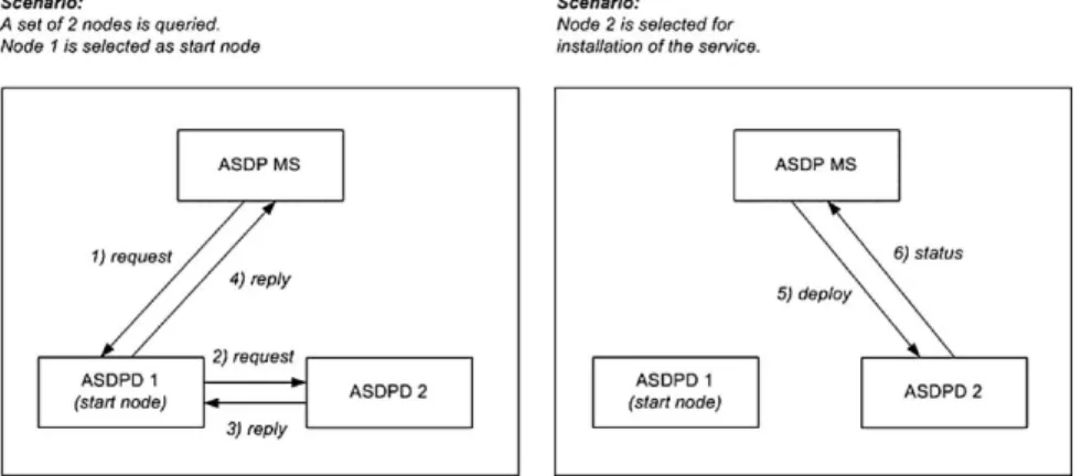
Network-level service deployment proceeds in four subsequent steps (see Fig.1): resource discovery, selection, resource allocation, and advertisement. We explain the protocol operation during these steps using a simplified scenario with only two participating nodes.
Protocol processing for the resource discovery and selection step is depicted in Fig.5a. A service deployment operation is initiated by a service provider via the user interface of the ASDP management station (ASDP MS). The ASDP MS opens a TLS connection and sends an initial request message (1) containing the service descriptor to the start node, which is explicitly specified in the deployment request.
The initial request message is then processed by the ASDP daemon running on the start node. In the resource discovery step, service-specific patterns are used
Fig. 5. Protocol operation in a simplified deployment scenario.
to process received messages. Therefore, on receipt of a request message control is passed to the patterns in the following order:
1. The capability function is executed to determine whether the visited node fulfills the service requirements. A score representing the node’s suitability is returned by the capability function.
2. The navigation pattern is executed to determine the actual state of the pattern’s finite-state-machine (FSM), and the corresponding aggregation function.
3. The aggregation pattern is executed. That is, the aggregation function determined in the previous step is executed in order to aggregate the obtained information.
4. The navigation pattern is executed again to determine whether other nodes have to be visited. The core protocol offers two possibilities to the navigation pattern; either a request or a reply message can be sent.
In our example, the navigation pattern decides to open a TLS connection and to forward the request message (2) to node 2, which processes the received request according to the given steps (I–IV). The navigation pattern instance on node 2 decides to send a reply message (3) on the open TLS connection in response, since no other node needs to be queried. On receiving a reply message, control is handed to the patterns in the same order (steps II–IV) as for request messages. The capability function is not started on receipt of a reply message, since the node capabilities have previously been evaluated on receipt of the request message. On receipt of the reply message, node 1 behaves accordingly and sends a reply message
(4) on the open TLS connection to the ASDP management station. At this point, the resource discovery step is finished and the result—the set of suitable nodes and their associated scores—is displayed on the management station. The selection of nodes to deploy the service components is done manually by the service provider via the user interface. In further work, however, we plan to specify a mapping algorithm which automates the node selection process.
Protocol processing for the resource allocation and advertisement step is depicted in Fig.5b. Resource allocation is initiated on the set of nodes which is selected by the service provider to run the service components. For the sake of simplicity, in our example, only node 2 is selected to run service components. The management station opens a TLS connection and sends a deploy message (5) directly to each selected node. On receipt of a deploy message, control is handed to the node level deployment protocol which installs the requested service components. A status message (6), sent on the opened TLS connection, informs the management station about the result of the deployment operation. Finally, the deployment result, returned in the status message, is displayed on the management station for verification through the service provider.
4. PROTOTYPE IMPLEMENTATION
We have implemented a prototype of the service deployment architecture in Java. The main goal of the implementation was to gain some experience with developing customized deployment protocols and to gather some initial data about the efficiency of different deployment patterns. This paper concentrates on describing the interfaces between the core protocol and the patterns, and present-ing three example patterns. For a more detailed description of the prototype, refer to [10].
4.1. Pattern Interfaces
The prototype provides each pattern class with a separate interface for ex-changing information with the core protocol: the navigation pattern interface, the aggregation pattern interface, and the capability function interface. In Fig.6, an overview of the implementation is presented. Parameters which are required for request messages, but not for reply messages are italicized. On receipt of a mes-sage (see Section 3.4) control is passed to the patterns in the following order: (1) capability function, (2) navigation pattern, (3) aggregation pattern, (4) navigation pattern (from left to right in Fig.6). Recall that the capability function is only executed on receipt of a request message.
All three pattern interfaces support the exchange of error messages with the core protocol. The localHost parameter which is passed to each pattern specifies
Fig . 6. Ov ervie w of the m odular protocol implementation.
the IP address of the local interface. This is required to identify the node which generated the error message. After its execution, each pattern returns an error list which is sent along with the next reply message towards the management station.
Parameters passed to (⇒) and returned (⇐) by the capability function are
⇒ parameterList—contains the capability function parameters (e.g., maximum
load) extracted from the received service descriptor;
⇐ score—specifies the node’s suitability as a short value.
Parameters passed to (⇒) and returned (⇐) by the navigation pattern during its first execution are
⇒ msList—contains the pattern-specific part of the received message, called
mobile states (these are used by the navigation pattern to determine the new distributed state according to its FSM);
⇐ aggregationFunction—specifies the name of the aggregation function that is
assigned to the new distributed pattern state.
Parameters passed to (⇒) and returned (⇐) by the aggregation pattern are
⇒ param—data structure which contains the following parameters: (a) the name
of the determined aggregation function, (b) the aggregation parameters extracted from the received service descriptor, (c) the scores returned by the previously executed capability functions, and (d) the list of already identified suitable nodes;
⇐ nodesList—contains the aggregated list of suitable nodes.
Parameters passed to (⇒) and returned (⇐) by the navigation pattern during its second execution are
⇒ msList—contains the pattern-specific part of the received message, called
mobile states;
⇒ peerHost—specifies the IP address of the host the message was received from; ⇒ navParam—specifies the navigation parameters extracted from the service
descriptor;
⇐ patternResult—specifies instructions about how the protocol should proceed
(e.g., send reply).
4.2. Deployment Patterns
We illustrate the interaction of the patterns with each other and with the core protocol by describing the implemented example patterns. Information among the three pattern classes is exchanged via the individual protocol interfaces with
the core protocol. In Section 2.2, we have identified the following inter-pattern dependencies:
• The aggregation pattern and the navigation pattern are closely related. That
is, all aggregation functions that are used by the FSM of the navigation pattern must be defined by the aggregation pattern.
• The aggregation pattern and the capability function must be designed to
match each other. That is, scores returned by the capability function must be interpreted by the aggregation pattern.
The ConstrainedRemoteEcho (CRE) navigation pattern we implemented is based on a pattern introduced in [8]. Instances of the CRE pattern communicate via the following pattern-specific messages, called mobile states: mlnit, mExplorer, mEcho, and mExplored. These messages trigger (a) state changes according to the pattern’s FSM, and (b) the execution of aggregation functions associated with the entered state. The CRE navigation pattern can be used to flood-dedicated remote domains. That is, the management station and the start node are not required to be part of a target domain. Instead, each node checks whether it resides within the target domain, and forwards the message to one node within the target network if necessary. We extended the original CRE pattern with a timeout mechanism to handle node failures. An initial timeout budget is specified as a pattern parameter in the service descriptor. The timeout mechanism is based on decreasing the timeout budget by a constant value on each visited node. Decreasing the timeout budget is necessary, since otherwise the timer would always expire first on the node which is closest to the management station, and information collected from nodes further down in the execution graph would be lost.
The FindBestNode (FBN) aggregation pattern we implemented is also based on a pattern described in [8] which matches the CRE navigation pattern. It aggregates collected information about visited nodes in a way that only one node—the one that best matches a given metric—is selected. The metric itself is defined by the capability function. The aggregation pattern simply takes the score returned by the capability functions as input. It defines three aggregation functions, onFirstExplorer, onEcho, and onSubExplorer, as specified by the FSM of the CRE navigation pattern. The FBN aggregation pattern maintains on each node a local list, in which it keeps the IP address of the node with the highest score discovered so far.
The LoadAverageNetwork (LAN) capability function we implemented eval-uates the network load of a visited node during the last 5 min. Additionally, it checks whether the visited node resides within a given network domain. There-fore, it requires three parameters to be specified in the service descriptor: (a) the maximum allowed load average, (b) the address of the desired domain, and (c) the corresponding address mask. On receipt of the first mExplorer message, the
capability function determines whether the node resides within the specified do-main. If this is not the case, a zero score is returned. Otherwise, the load average during the last 5 min is obtained, and the score is computed and returned by the capability function.
5. USE CASE: VPN DEPLOYMENT
In this section, we describe a sample scenario for the deployment of a virtual private network (VPN) using the automated service deployment protocol and the patterns introduced in the last section. We assume that a network manager wants to set up a VPN between network domains of different sizes. In general, each domain consists of several programmable nodes running an ASDP daemon. One node per domain is to be selected by the service deployment protocol to act as IPSec gateway for the VPN. A node acting as IPSec gateway is required to have sufficient processing resources to handle the encapsulation of IP packets from other hosts within its domain in a timely fashion.
In a traditional, manual deployment scenario, the network manager must know the identities of all nodes within the three domains. Using the automated service deployment architecture this knowledge is not required. The workload for the network manager is reduced to the following tasks: (i) specification of the service descriptor using the generic description format XML schema; (ii) confir-mation of the nodes identified by the ASD protocol to deploy a VPN endpoint; and (iii) verification of the deployment result. In fact, using the CRE pattern only one domain can be queried at a time. Thus, for each domain a single deployment operation must be started. However, the CRE pattern could easily be extended to be able to query multiple remote domains.
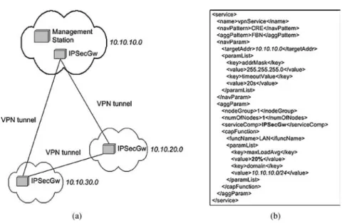
The network setup of the VPN and the service descriptor for one deploy-ment operation—for deploydeploy-ment of an IPSec gateway in domain 10.10.10.0—is depicted in Fig.7. The ASD protocol, applying the CRE navigation pattern, the FBN aggregation pattern, and the LAN capability function, automatically queries all nodes in the specified domain for the capabilities specified in the service descriptor. The aggregation parameter numOfNodes specifies that only one node is required to deploy the IPSecGW service component, and the capability pa-rameter maxLoadAvg specifies that this node is required to have a load average of less than 20%. After the ASD protocol has identified a suitable node in the specified domain, the network manager initiates the setup of the IPSec gateway by confirming the node selection. Subsequently, installation and configuration of the IPSec gateway through a node level deployment tool is triggered by the service deployment architecture. Finally, the result of the deployment is returned to the management station.
Fig. 7. Setup of a virtual private network using the ASD architecture. (a) Network setup of the VPN service. (b) Instance-specific service descriptor.
6. EXPERIMENTAL RESULTS 6.1. Overlay Generation on PlanetLab
PlanetLab is a globally distributed platform for developing and testing ser-vices under conditions as experienced in the real Internet. To conduct tests on PlanetLab an overlay topology (see Fig. 2) on which the service deployment architecture operates is required. Our approach is to construct a static overlay topology based on measured round-trip-times (RTTs) between PlanetLab nodes. Scriptroute [11] is a tool that can be used to measure RTTs between PlanetLab nodes running a Scriptroute server. The overlay topology is constructed according to the following algorithm: Node x is connected via a vertex to node y in the graph, if the measured RTT from node x to node y is smaller than a maximum RTT value which can be arbitrarily chosen.
6.2. Resource Discovery Measurements
We measured the discovery latency and the generated network traffic that is required for querying all European PlanetLab nodes with the implemented test patterns. Our measurements are conducted on the basis of the overlay topology generation mechanism described above. Hence, for all tests the same RTT mea-surement data was used. Furthermore, node planetlabl.inria.fr was selected as start
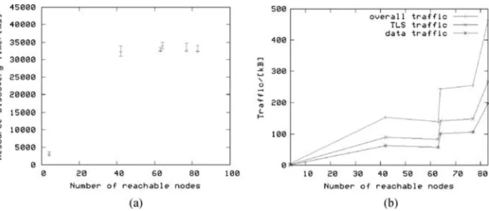
Fig. 8. Measurement results for resource discovery tests on PlanetLab. (a) Discovery latency vs. number of nodes. (b) Generated traffic vs. number of nodes.
node for all tests. The management station on which deployment operations are initiated is installed on a PlanetLab node at the ETH Zurich site. ASDP daemons are installed on all 83 European PlanetLab nodes. We used six different overlay network topologies with varying sizes (from 4 to 83 nodes) and varying aver-age vertices degrees (approximately from 1 to 50) for the discovery latency and network traffic measurements.
For measuring the discovery latency, we included a timer in the management station code, which is started when the initial request is sent. The timer is stopped when a reply from the start node is received. Hence, the measured time includes only the resource discovery latency, but not the time for the installation of service components. The initial timeout budget of the CRE pattern is set to 30 s, since we expect a deployment operation over a maximum of 83 nodes to be completed within this time in case node failures do not occur. Discovery latency measurement results are depicted in Fig.8a. For all measurements with more than four nodes, except one, resource discovery completed in between 30 and 41 s. When analyzing the measurement logs, we discovered that during all those deployment operations timeouts occurred. In a network with real Internet conditions like the PlanetLab test bed, this is not surprising. Hence, we reason that by decreasing the initial timeout budget, shorter discovery latencies can be achieved. Ideally, the timeout occurs after all correctly working nodes have sent their reply messages. For our measurements we used a static overlay network topology. Usage of a dynamic topology that takes node failures into account could further improve performance of the CRE navigation pattern, since timeouts would be less likely to occur.
For measuring the generated network traffic, we logged the size of each message that was sent on the ASDP daemons. We calculated the total generated traffic on all ASDP daemons. Moreover, we separately counted the number of bytes
used for TLS authentication messages. Traffic measurement results are depicted in Fig.8b. The total number of bytes sent during a deployment operation increases with the number of reachable nodes. For visiting the maximum of 83 nodes less than 500 kB of traffic are generated. TLS authentication traffic accounts for approximately 60% of the total generated traffic. That is, for each opened connection approximately 3 kB of TLS authentication traffic is sent. Using the CRE navigation pattern, on each opened TLS connection exactly one request and reply message pair is sent. Hence, the total generated traffic increases linearly with the average number of opened TLS connections.
6.3. Comparison of the CRE Pattern with a Centralized Pattern
The discovery latency and network traffic measurements with the distributed CRE navigation pattern presented in the last section clearly demonstrate the usabil-ity of our architecture. However, they do not show the performance improvement that can be achieved using our flexible service deployment architecture. There-fore, we conducted another test on PlanetLab which compares performance of the distributed CRE pattern with a centralized pattern.
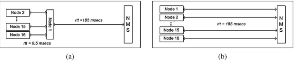
The test setup is the following: 16 nodes at one North American campus site are queried from a European network management station. For the distributed scenario, we use the deployment patterns described in Section 4.2. Moreover, we manually generate the following overlay structure: The network management station is connected to exactly 1 American node, and the 15 remaining PlanetLab nodes in the campus network are connected to this node (see Fig.9a). For the centralized scenario, the management station queries each of the 16 campus nodes individually (see Fig.9b). We implemented (a) a centralized navigation pattern which simply sends back a reply message to the manager, (b) a capability function which gets the node’s load, and (c) a dummy aggregation pattern. In the centralized scenario, aggregation of the gathered results is executed on the management station after all replies have been received. For each setup, we measure (a) the discovery latency, i.e., the time for a complete resource discovery including aggregation of the results, and (b) the weighted traffic, i.e., the overall traffic on each connection
Fig. 9. Comparison with centralized pattern. (a) Test setup for CRE pattern. (b) Test setup for centralized pattern.
Table I. Measurement Results for Tests with CRE and Centralized Pattern Latency (average, ms) Latency (deviation, ms) Weighted traffic (kB ms) CRE pattern 17,249.625 2162.90 3968.25 Centralized pattern 11,927.9375 1406.35 7400
weighted with the round-trip-time of the connection. Measurement results are summarized in TableI.
The measurement results show some very interesting effects. Obviously, there is a trade-off between discovery latency and generated traffic for the two patterns. One unexpected result is that the centralized pattern performs about 30% faster than the distributed pattern. There are two reasons for this behavior. First, in the centralized scenario, the 16 parallel overseas connections are opened si-multaneously not consecutively. Hence, the latency they impose has less influence on the overall discovery latency. Second, we observed that setting up TLS/SSL connections between highly loaded PlanetLab nodes imposes a high latency. In the distributed scenario, we have 15 of these costly connections. Nevertheless, the distributed pattern only generates about half as much weighted traffic as the centralized pattern. The strength of our pattern-based approach is that based on the given requirements (latency vs. traffic optimization), and the given network conditions (network load vs. node load) the appropriate pattern can be chosen and applied very easily.
7. CONCLUSIONS AND FUTURE WORK
In this paper, we presented a flexible service deployment architecture for the automated, on-demand deployment of distributed services in programmable networks. The goal of our approach is to support the customization of the deployment protocol to specific service requirements. We achieved this goal by developing (i) a modular protocol architecture which is based on three classes of exchangeable deployment patterns, and (ii) a three-tier service description model which uses XML as service description language. Our implementation of the service deployment architecture includes six example deployment patterns, two of each pattern class. We have shown how the implemented patterns can be applied in a concrete deployment scenario, i.e., for setting up a virtual private network. Furthermore, we tested our pattern-based deployment protocol in the PlanetLab network. Tests have shown that a resource discovery operation over 83 PlanetLab nodes completes in around 40 s, while generating less than 500 kB of traffic within the network. Moreover, we demonstrated how the protocol performance can be optimized for a certain scenario by applying different deployment strategies. Our
pattern-based architecture provides the necessary flexibility to easily customize deployment protocols to the given network and node conditions. Further work will be to investigate into dynamic approaches for generating the required overlay structure, and to extend the basic set of implemented deployment patterns.
REFERENCES
1. R. Haas, P. Droz, and B. Stiller, Distributed service deployment over programmable networks, in
DSOM 2001, Nancy, France, 2001.
2. R. Keller and B. Plattner, Self-configuring active services for programmable networks, in Pro-ceedings of the Fifth Annual International Working Conference on Active Networks (IWAN 2003), Kyoto, Japan, December 2003.
3. D. Oppenheimer, J. Albrecht, D. Patterson, and A. Vahdat, Scalable wide-area resource discovery,
UC Berkeley Technical Report UCB//CSD-04-13342004.
4. A. Bavier, M. Bowman, B. Chun, D. Culler, S. Karlin, S. Muir, L. Peterson, T. Roscoe, T. Spalink, and M. Wawrzoniak, Operating system support for planetary-scale services, in Proceedings of the
First Symposium on Network Systems Design and Implementation (NSDI), March 2004.
5. M. Bossardt, T. Egawa, H. Otsuki, and B. Plattner, Integrated service deployment for active networks, in Proceedings of the Fourth Annual International Working Conference on Active
Networks, IWAN, number 2546 in Lecture Notes in Computer Science, Zurich, Switzerland,
December 2003. Springer Verlag, Berlin.
6. K.-S. Lim and R. Stadler, Developing pattern-based management programs, in Proceedings of 4th IFIP/IEEE International Conference on Management of Multimedia Networks and Services (MMNS 2001), Chicago, USA, 2001.
7. K.-S. Lim and R. Stadler, A navigation pattern for scalable Internet management, in Proceedings of the IFIP/IEEE International Symposium on Integrated Network Management (IM’Ol), Seattle, USA, May 2001.
8. M. Bossardt, A. Muhlemann, R. Ziircher, and B. Plattner, Pattern based service deployment for active networks, in Proceedings of the Second International Workshop on Active Network
Technologies and Application (ANTA 2003), Osaka, Japan, May 2003.
9. M. Bossardt, R. Hoog Antink, A. Moser, and B. Plattner, Chameleon: Realizing automatic service composition for extensible active routers, in Proceedings of the Fifth Annual International Working
Conference on Active Networks (IWAN 2003), Kyoto, Japan, Lecture Notes in Computer Science,
Springer Verlag, Berlin, December 2003.
10. D. Brauckhoff, Patterns for service deployment in programmable networks, Master’s thesis, ETH Zurich, 2004.
11. N. Spring, D. Wetherall, and T. Anderson, Scriptroute: A public Internet measurement facility, in Proceedings of the USENEX Symposium on Internet Technologies and Systems (USITS), 2003.
Daniela Brauckhoff received a Master of Electrical Engineering from the
Technical University of Berlin in 2004. During her master thesis at the Swiss Federal Institute of Technology Zurich (ETH), she worked on pattern-based service deployment. Early in 2005, she started her PhD at ETH Zurich, where she is working on a European research project on distributed monitoring.
Matthias Bossardt received a Master of Electrical Engineering from the
the ABB Switzerland Research Prize. In 2000, he started his PhD at ETH Zurich. His main research interest is in the field of flexible network services, specifically their management and their application to network security.
Bernhard Plattner is a Professor of Computer Engineering at ETH Zurich,
where he leads the communication systems research group. His research currently focuses on applications of communication systems and higher layer protocols, and on new network architectures. Specifically, he has directed research on active networks, starting as early as 1996. He is also interested in new approaches for dynamic service creation and management, as well as practical aspects of information security.