HAL Id: hal-03077523
https://hal.archives-ouvertes.fr/hal-03077523
Submitted on 6 Jan 2021
HAL is a multi-disciplinary open access
archive for the deposit and dissemination of
sci-entific research documents, whether they are
pub-lished or not. The documents may come from
teaching and research institutions in France or
abroad, or from public or private research centers.
L’archive ouverte pluridisciplinaire HAL, est
destinée au dépôt et à la diffusion de documents
scientifiques de niveau recherche, publiés ou non,
émanant des établissements d’enseignement et de
recherche français ou étrangers, des laboratoires
publics ou privés.
To cite this version:
Stefan Kuczera, Axel Rüter, Kevin Roger, Ulf Olsson. Two Dimensional Oblique Molecular Packing
within a Model Peptide Ribbon Aggregate. ChemPhysChem, Wiley-VCH Verlag, 2020, 21 (14),
pp.1519-1523. �10.1002/cphc.201901126�. �hal-03077523�
12 13 14 15 16 17 18 19 20 21 22 23 24 25 26 27 28 29 30 31 32 33 34 35 36 37 38 39 40 41 42 43 44 45 46 47 48 49 50 51 52 53 54 55 56 57
diffraction investigation on a flow-aligned dispersion of these self-assembly structures. The two-dimensional wide-angle X-ray scattering pattern suggests that peptide pack in a two-dimen-sional oblique lattice, essentially identical to the crystalline packing of polyalanine, An(for n > 4). One side of the oblique
unit cell, corresponding to the anti-parallel β-sheet, is oriented along the ribbon’s axis. Together with recently published small angle X-ray scattering data of the same system, this work thus yields a detailed description of the self-assembled ribbon aggregates, down to the molecular length scale. Notably, our results highlight the importance of the crystalline peptide packing within its self-assembly aggregates, which is often neglected.
The self-assembly of peptide molecules into fibre-like structures has been studied for decades as it is key in the understanding of many neurodegenerative diseases such as Alzheimer’s or Parkinson’s.[1]
Also, a large array of peptide-based materials are promising for nanotechnologies and medical applications.[2]
Peptide aggregates are typically β-sheet rich and can have different shapes, such as long fibrils, ribbons or hollow nanotubes.[3–12]
While numerous studies have been reporting on different aggregate morphologies, there is limited knowledge about the internal aggregate structures, i. e. the local packing of the peptide molecules within the aggregates. Knowledge of the molecular packing within these aggregates is important for the understanding of these fascinating self-assemblies including the development of quantitative thermodynamic models.[13,14]
ordered, with two dimensional (2D) or three dimensional (3D)[18,19]
crystalline packing of the peptide molecules. The fact that the aggregates are crystalline is important. It means they essentially cannot solubilize other molecules forming mixed aggregates. Also, it explains why peptide fibrillar aggregates appear to be very rigid having long persistence lengths.[20–23]
In the case of 3D crystals, the self-assembly can be understood as a classical crystallization and precipitation from a supersatu-rated solution.[24]
When there is only 2D crystalline order, the aggregates typically involve a monolayer of peptide molecules with in-plane crystalline ordering. Crystalline monolayers have been reported for hollow nanotubes.[15,25–27]
and for ribbon-like aggregates.[16,17,27]
A crystalline bilayer structure has also been reported for peptide nanotubes.[4,5,25,28]
In the case of 2D crystalline order the thermodynamic state is less clear. In fact, it is still not known whether the observed self-assemblies correspond to an equilibrium state, character-ized by an equilibrium size distribution, like for surfactant micelles, or whether they rather are kinetically trapped precipitates. In the present communication we address the local crystalline packing of a model peptide, A10K (A = alanine, K =
lysine), which forms twisted ribbon aggregates. The structure of the aggregates has been characterized previously using small and wide-angle X-ray scattering in combination with electron microscopy[14,17]
Here, we use flow alignment of the ribbon aggregates to obtain an oriented diffraction pattern. Based on the oriented pattern, we suggest a 2D oblique packing where one site of the unit cell coincides with the β-sheet direction and is oriented parallel to the main axis of the aggregate.
A10K self-assembles in water into ribbon-like aggregates
composed of ca. 15 laminated β-sheets.[17]
At rest, a 5 wt% A10K
sample shows static birefringence when analyzed with polar-ized light (Figure 1a) indicating a nematic ordering of the ribbons. Figure 1b shows a series of images taken when flowing the sample through the capillary used for the X-ray experiments of radius 0.75 mm at different flow rates using polarized light to detect optical birefringence. The orientation of the analyzer and polarizer is shown in Figure 1c. Due to high shear forces associated with sample loading and peristaltic pumping, the peptide aggregates are broken into segments of shorter lengths as confirmed by DLS experiments (Figure S1 in SI). As a consequence the nematic ordering and birefringence is lost as seen in Figure 1b for the fluid at rest (flow rate 0.8 ml/min.). However, during flow, a characteristic birefringence pattern of alternating light and dark bands is observed, indicating an alignment of the ribbon aggregates in the flow direction. This
[a] Dr. S. Kuczera, Dr. A. Rüter, Prof. Dr. U. Olsson
Division of Physical Chemistry, Lund University, SE-22100 Lund, Sweden E-mail: stefan.kuczera@gu.se
[b] Dr. K. Roger
Laboratoire de Génie Chimique, Université de Toulouse, CNRS, Institut National Polytechnique de Toulouse, Université Paul Sabatier, 31030 Toulouse, France
[c] Dr. S. Kuczera
Present adress: Institute of Clinical Sciences, Sahlgrenska Academy, Gothenburg University, Gothenburg, SE-405 30, Sweden
Supporting information for this article is available on the WWW under https://doi.org/10.1002/cphc.201901126
© 2020 The Authors. Published by Wiley-VCH Verlag GmbH & Co. KGaA. This is an open access article under the terms of the Creative Commons Attribution Non-Commercial NoDerivs License, which permits use and distribution in any medium, provided the original work is properly cited, the use is non-commercial and no modifications or adaptations are made.
2 3 4 5 6 7 8 9 10 11 12 13 14 15 16 17 18 19 20 21 22 23 24 25 26 27 28 29 30 31 32 33 34 35 36 37 38 39 40 41 42 43 44 45 46 47 48 49 50 51 52 53 54 55 56 57
birefringent pattern disappears within a few seconds after cessation of flow. Restarting the flow, the birefringence pattern reappears, showing that the flow induced transition is rever-sible.
As shown in Figure 1b there is a transition from two bright bands for lower flow rates to three distinct bright bands for higher flow rates. This behaviour can be qualitatively described by the approach of Tordella,[29]
where retardation at each point in the circular capillary is assumed to be proportional to the local shear stress that varies linearly with the radial direction. For a Newtonian fluid this would correspond to a Poiseuille flow. By integrating over the thickness of the capillary at each normalized offset x ¼ x0
=R (see Figure 1c), the retardation �ðxÞ can be expressed as �ðxÞ ¼ C pffiffiffiffiffiffiffiffiffiffiffiffiffi1 x2þx 2 2log 1 þpffiffiffiffiffiffiffiffiffiffiffiffiffi1 x2 1 pffiffiffiffiffiffiffiffiffiffiffiffiffi1 x2 " # (1)
with C being a constant proportional to the flow rate. The normalized intensity I/I0under cross polarizers with I0being the
intensity of the incoming light is then given as
I=I0¼
1
2ð1 cos �Þ: (2)
Determining C quantitatively under our experimental con-ditions is difficult. However, approximating C to be in the range between 1 and 5 for the flow rates shown in Figure 1b, one obtains intensity profiles that exhibit a transition from two (normalized) intensity maxima to three intensity maxima at C = 3 (Figure 1c). Arguably, this model can only be seen as rough approximation, as, for example, a fully bright capillary as expected at C = 3 is not observed. As stated by Tordella,[29]
deviations from the model might be due non-linearities in the retardance-stress relation, or the lens effect of the capillary, or
both. For the X-ray experiments described in the following we concentrate on a single flow rate of 4.5 ml/min.
The 2D wide-angle X-ray pattern of the sample at rest (Figure 2a) shows three high intensity Debye-Scherer rings, typical for powder diffraction, corresponding to reflections observed in earlier work.[17]
The variation of intensity along each of the rings in angular direction cannot be related to an alignment of the rod-like aggregates in agreement with the lack of birefringence observed under polarized light under the same conditions. There is, however, an anisotropy related to the shape of the capillary that gives rise to increased intensities in the qydirection as compared to the qxdirection due to a shorter
path length through the fluid and thus less absorption. The pattern at a flow rate of 4.5 ml/min is similar to the one at rest (Figure 2b). This indicates that only a minor fraction of the ribbon aggregates are flow aligned, presumably near the capillary wall where the shear stress is the highest. However, when subtracting the pattern at rest from the pattern at 4.5 ml/ min, an anisotropic diffraction pattern is clearly observed (Figure 2c).
Based on the findings for the packing of the A6K tubular
aggregates[15,26] and the observation that we deal with a 2D
structure for the aggregate,[17] we suggest that the A 10K
peptides are packed in an oblique (2D monoclinic) lattice within the ribbon aggregates, as illustrated in Figure 3a. The corners of the unit cell are occupied by A10K peptides aligned
perpendic-ularly to the plane of the unit cell with either parallel or antiparallel orientation of the carboxyl end (lysine head). The direction of the β-sheet, i. e. the direction of the hydrogen bonding, is set to be along the edge a while the lamination distance of the β-sheets is set to be perpendicular to edge a. As the effective electron density for oppositely orientated peptides in the aggregate is too similar with respect to the scattering experiment parallel and antiparallel alignment cannot be distinguished in our measurements. However, based on previous findings we propose the orientation pattern as shown
Figure 1. (a) Photograph of an aqueous solution of A10K peptide in the preparation vial at a peptide concentration of 5 wt % under polarized light. (b) Series of
photographs of the flow capillary used for scattering experiment under polarized light at different flow rates (label in ml/min). Slight variations in the image brightness between different flow rates are due to different exposure settings of the camera. (c) Magnification of the photograph at a flow rate of 4.5 ml/min. Three bright bands indicating birefingence (and thus alignment) are clearly visible. Observe that the capillary is enclosed by a metal casing and only visible in the opening used for beam exposure. The extent of the capillary is indicated by the dashed lines. Directions of polarizer (p) and analyzer (a) as well as the flow direction are also shown. (d) Theoretical curves for the normalized intensity I/I0as function of the normalized offset x
0=R for different vaules of C, with C being
a constant proportional to the flow rate.
1520
12 13 14 15 16 17 18 19 20 21 22 23 24 25 26 27 28 29 30 31 32 33 34 35 36 37 38 39 40 41 42 43 44 45 46 47 48 49 50 51 52 53 54 55 56 57
in Figure 3a. Along edge a, the β-sheet direction, we choose an antiparallel arrangement, as has been found for the shorter analogue A6K.[15]Also polyalanine, An, which only differs by the
lysine group from the peptide studied here, naturally forms antiparallel β-sheets for n > 3.[30]
Both these two systems also show a very similar 1D diffraction pattern to the one observed here. Along edge b we do also propose an alternating orientation pattern as this maximizes the distance between the bulky and charged lysine heads. In Figure 3b a model of an aggregate with 15 laminated/stacked β-sheets build up from this model is shown. Figure 3c represents a top view of the lattice at the position indicated in Figure 3b.
In order to test the lattice model against the measured diffraction pattern a Miller index, hk, has to be assigned to each of the observed reflections. The largest spacing is found to be 5.3 Å and is assigned to the 01 reflection, representing the spacing between laminated β-sheets. This assignment is supported by a model for crystalline polyalanine suggested by Arnott et al.[31] where the repeat distance for β-sheet stacking
was also 5.3 Å. The middle ring corresponds to a spacing of 4.4 Å and is assigned with to 10. The outermost ring with a spacing of 3.7 Å is assigned with the 11 reflection. This set of assignments results in a primitive unit cell as shown in Figure 3a with the following parameters: a = 4.44 Å, b = 5.42 Å and γ = 100° as determined by least square regression. From this follows that the peptide-peptide distance within the β-sheet is about 4.44 Å, similar to the value of 4.7 Å often quoted for
β-sheets in other systems.[32]
As the aggregate consists of mainly alanine amino acids, where the side-group is the second smallest of all amino acid, a slightly smaller value compared to other systems is not unreasonable. In particular, we emphasize that the smaller value is not caused by a calibration error, as the same distance has been observed in previous work with well-calibrated setups[17]
for the same system. An overview of all assigned reflections and unit cell parameters is found in Table 1.
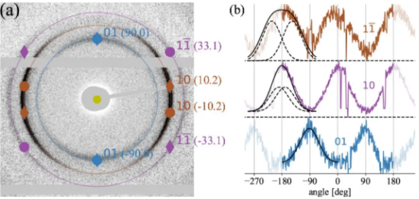
The positions of the three main reflections 01, 10 and 11 in the scattering pattern for an ideal lattice with the proposed unit cell are indicated in Figure 4a on top of the measured differ-ence pattern (circles). Please note that a (Figure 3a) is set parallel to qxin accordance with the alignment of the fibre axis
with the flow direction. Furthermore, one has to consider that
Figure 2. 2D wide-angle X-ray diffraction pattern at rest (a), during flow at 4.5 ml/min (b) (both background subtracted) and difference pattern (c). Flow/
capillary direction is indicated as well as the spacing for each of the rings
Figure 3. Model for the crystalline peptide aggregate. (a) Oblique unit cell (solid line) and part of the lattice (dashed line) are shown. Peptide positions and
proposed orientations are indicated. β-sheet direction is along edge “a”. (b) Peptide aggregate with 15 stacked β-sheets. (c) Top view of aggregate at highlighted unit cell.
Table 1. Table of assigned reflections and resulting unit cell parameters.
reflection q-value [Å 1] distance [Å]
01 1.18 5.3 10 1.44 4.4 11 1:69 3:7 parameter value a 4.44 Å b 5.42 Å γ 100°
2 3 4 5 6 7 8 9 10 11 12 13 14 15 16 17 18 19 20 21 22 23 24 25 26 27 28 29 30 31 32 33 34 35 36 37 38 39 40 41 42 43 44 45 46 47 48 49 50 51 52 53 54 55 56 57
there is a degree of freedom with respect to the rotation of the aggregate along the long (fibre) axis. Thus, scattering from a unit cell mirrored along side a has to be taken into account, represented by diamonds in Figure 4a. Consequently, one expects four peaks for the 10 and 11 rings. For the 01 ring the peaks from the regular and mirrored unit cell coincide and therefore only two peaks are expected.
The measured difference pattern essentially shows two maxima for each of the rings, as can be seen in the angular plots in Figure 4b. While this is expected for the innermost ring, the theoretical model predicts four peaks for the other two rings. However, the width of the flow-induced orientation distribution for the aggregates needs to be taken into account. As the two peaks for the 01 ring coincide, the width of the distribution can be extracted from this reflection. Fitting a Gaussian to the angular data as shown in Figure 4b results in an approximate width (FWHM) of 72°, which in theory is the same
for the other reflections. Consequently, the 11 reflections appear as one broader peak, as the expected separation between them is only 20°. In Figure 4b the peak is modelled as
the sum of two identical Gaussian functions with the same FWHM as for the 01 reflection and is in agreement with the experimental data. For the 20 reflection the angular distance between the two maxima is about 66°according to the model.
The peak can be modelled in the same fashion as for the 11 reflection giving rise to a plateau in the peak also found in the experimental data as shown in Figure 4b. There is a slight asymmetry with respect to the peak centre, probably caused by experimental imperfections.
The reflections 01, 10 and 11 are the reflections with the largest spacing expected from the model with the given unit cell parameters. The fourth largest spacing corresponds to the 11 reflection which is not observed, likely because of too low intensity. For the 02 reflection, the fifth largest spacing, a small peak is found in the 1D azimuthal projection of the 2D pattern. However, intensity is too weak for a 2D analysis for this reflection.
Overall, we conclude that the A10K peptides pack into an 2D
oblique unit cell in ribbon-like colloidal aggregates. One side of
the unit cell, the β-sheet direction, is parallel with the ribbon main axis. This is consistent with the rather general observation that the β-sheets are parallel with the fibril axis in β-sheet rich peptide fibrils (or similar aggregates).[32]
As discussed above, only a fraction of the aggregates align significantly when flowing at 4.5 ml/min, although the fraction is large enough to show an optical birefringence. Presumably this fraction is close to the capillary wall where the shear stress is expected to be highest. It shall further be noted that complementary SAXS measurements at a lower flow rate of 2.3 ml/min show a similar weak alignment pattern (see Fig-ure S2 in SI) as found for WAXS. Here, we have focused only on the 2D crystal structure and the unit cell orientation in the ribbons. However, it would also be interesting to study the partial alignment in more detail. The question concerns whether the observed alignment of the peptide aggregates is continuous or if there is a flow induced isotropic-to-nematic (phase) transition as has been discussed for e. g. semi-flexible wormlike micelles, with shear banding flow observed in Couette geometry.[33,34]
Experimental Section
A10K peptides were acquired from CPC Scientific, Inc. as
trifluor-oacetate (tfa) stabilized salts with a sample purity of 98 %. No further purification was performed. The freeze-dried peptide powder was dissolved in H2O to a final sample concentration of
5 wt %. The sample was stored for about a month at room temperature before the measurement.
The flow setup consisted of a closed loop of rubber tubing connected to a quartz capillary (1.5 mm diameter) and a peristaltic pump (ISMATEC REGLO Digital) to drive the fluid. Due to the high viscosity of the solution (zero-shear viscosity > 10 000 Pas) it was necessary to centrifuge the loading syringe that subsequently was used for filling the flowing loop.
Wide-angle X-ray diffraction (WAXD) measurements were per-formed at the P03 beamline[35,36] at the PETRA III storage ring at
DESY. An X-ray wavelength of 0.95 Å and a sample-to-detector distance of 98.1 mm were used. The detector was a Pilatus 300-k detector (Dectris) with a pixel size of 172 μm × 172 μm.
Figure 4. (a) Expected scattering pattern for oblique lattice (parameters given in text) for the main reflections on top of measured difference pattern from
Figure 2c. The angular position for each reflection is given in parenthesis (degrees). Circles represent reflections from the lattice shown in Figure 3a while diamonds represent reflections from the mirrored unitcell. (b) Angular intensities along reflection rings. Solid black lines are a Gaussian fit for 01 and the sum of two identical Gaussians with angular separation (dashed lines) for 21 and 20. Note that the angular range is periodically expanded for better visualization.
1522
12 13 14 15 16 17 18 19 20 21 22 23 24 25 26 27 28 29 30 31 32 33 34 35 36 37 38 39 40 41 42 43 44 45 46 47 48 49 50 51 52 53 54 55 56 57
Conflict of Interest
The authors declare no conflict of interest.
Keywords: aggregation · flow alignment · peptides · structure
elucidation · X-ray diffraction
[1] B. Caughey, P. T. Lansbury, Annu. Rev. Neurosci. 2003, 26, 267–298. [2] G. Wei, Z. Su, N. P. Reynolds, P. Arosio, I. W. Hamley, E. Gazit, R.
Mezzenga, Chem. Soc. Rev. 2017, 46, 4661–4708.
[3] H. Xu, Y. Wang, X. Ge, S. Han, S. Wang, P. Zhou, H. Shan, X. Zhao, J. R. Lu, Chem. Mater. 2010, 22, 5165–5173.
[4] S. Vauthey, S. Santoso, H. Gong, N. Watson, S. Zhang, Proc. Natl. Acad.
Sci. USA 2002, 99, 5355–5360.
[5] K. Lu, J. Jacob, P. Thiyagarajan, V. P. Conticello, D. G. Lynn, J. Am. Chem.
Soc. 2003, 125, 6391–6393.
[6] S. Bucak, C. Cenker, I. Nasir, U. Olsson, M. Zackrisson, Langmuir 2009, 25, 4262–4265.
[7] J. P. Schneider, D. J. Pochan, B. Ozbas, K. Rajagopal, L. Pakstis, J. Kretsinger, J. Am. Chem. Soc. 2002, 124, 15030–15037.
[8] A. Aggeli, M. Bell, N. Boden, J. N. Keen, P. F. Knowles, T. C. B. McLeish, M. Pitkeathly, S. E. Radford, Nature 1997, 386, 259–262.
[9] A. Aggeli, I. A. Nyrkova, M. Bell, R. Harding, L. Carrick, T. C. B. McLeish, A. N. Semenov, N. Boden, Proc. Natl. Acad. Sci. USA 2001, 98, 11857– 11862.
[10] H. Yokoi, T. Kinoshita, S. Zhang, Proc. Natl. Acad. Sci. USA 2005, 102, 8414–8419.
[11] S. Zhang, Nat. Biotechnol. 2003, 21, 1171–1178. [12] I. W. Hamley, Soft Matter 2011, 7, 4122–4138.
[13] I. A. Nyrkova, A. N. Semenov, A. Aggeli, N. Boden, Eur. Phys. J. B 2000,
17, 481–497.
[14] A. Rüter, S. Kuczera, D. J. Pochan, U. Olsson, Langmuir 2019, 35, 5802– 5808.
Akerfeldt, S. Linse, Soft Matter 2015, 11, 414–21.
[22] V. Castelletto, I. Hamley, C. Cenker, U. Olsson, J. Phys. Chem. B 2010, 114, 8002–8008.
[23] M. J. Krysmann, V. Castelletto, J. E. McKendrick, L. A. Clifton, I. W. Hamley, P. J. F. Harris, S. M. King, Langmuir 2008, 24, 8158–8162. [24] I. V. Markov, Crystal Growth for Beginners Fundamentals of Nucleation,
Crystal Growth and Epitaxy, World Scientific Publishing Co. Pte. Ltd.,
Singapore, 2nd edn., 2008.
[25] W. S. Childers, R. Ni, A. K. Mehta, D. G. Lynn, Curr. Opin. Chem. Biol. 2009,
13, 652–659.
[26] D. A. Middleton, J. Madine, V. Castelletto, I. W. Hamley, Angew. Chem.
Int. Ed. 2013, 52, 10537–10540; Angew. Chem. 2013, 125, 10731–10734.
[27] I. W. Hamley, A. Dehsorkhi, V. Castelletto, Chem. Commun. 2013, 49, 1850–1852.
[28] A. K. Mehta, K. Lu, W. S. Childers, Y. Liang, S. N. Dublin, J. Dong, J. P. Snyder, S. V. Pingali, P. Thiyagarajan, D. G. Lynn, J. Am. Chem. Soc. 2008,
130, 9829–9835.
[29] J. P. Tordella, J. Appl. Polym. Sci. 1963, 7, 215–229.
[30] T. Asakura, M. Okonogi, K. Horiguchi, A. Aoki, H. Saitô, D. P. Knight, M. P. Williamson, Angew. Chem. Int. Ed. 2012, 51, 1212–1215; Angew. Chem.
2012, 124, 1238–1241.
[31] S. Arnott, S. D. Dover, A. Elliott, J. Mol. Biol. 1967, 30, 201–208. [32] L. C. Serpell, Biochim Biophys Acta Mol Basis Dis 2000, 1502, 16–30 [33] U. Olsson, J. Börjesson, R. Angelico, A. Ceglie, G. Palazzo, Soft Matter
2010, 6, 1769–1777.
[34] G. Porte, J.-F. Berret, J. L. Harden, J. Phys. II 1997, 7, 459–472.
[35] C. Krywka, H. Neubauer, M. Priebe, T. Salditt, J. Keckes, A. Buffet, S. V. Roth, R. Doehrmann, M. Mueller, J. Appl. Crystallogr. 2012, 45, 85–92. [36] A. Buffet, A. Rothkirch, R. Döhrmann, V. Körstgens, M. M. Abul Kashem,
J. Perlich, G. Herzog, M. Schwartzkopf, R. Gehrke, P. Müller-Buschbaum, S. V. Roth, J. Synchrotron Radiat. 2012, 19, 647–653.
Manuscript received: November 25, 2019 Revised manuscript received: April 29, 2020 Version of record online: June 23, 2020