HAL Id: cea-01810083
https://hal-cea.archives-ouvertes.fr/cea-01810083
Submitted on 7 Jun 2018
HAL is a multi-disciplinary open access
archive for the deposit and dissemination of
sci-entific research documents, whether they are
pub-lished or not. The documents may come from
teaching and research institutions in France or
abroad, or from public or private research centers.
L’archive ouverte pluridisciplinaire HAL, est
destinée au dépôt et à la diffusion de documents
scientifiques de niveau recherche, publiés ou non,
émanant des établissements d’enseignement et de
recherche français ou étrangers, des laboratoires
publics ou privés.
Model-Driven Multi-Level Safety Analysis of Critical
Systems
Nataliya Yakymets, Matthieu Perin, Agnes Lanusse
To cite this version:
Nataliya Yakymets, Matthieu Perin, Agnes Lanusse. Model-Driven Multi-Level Safety Analysis of
Critical Systems. Systems Conference (SysCon), 2015 9th Annual IEEE International, Apr 2015,
Vancouver, Canada. �cea-01810083�
Model-Driven Multi-Level Safety Analysis of Critical
Systems
Nataliya Yakymets, Matthieu Perin, Agnes Lanusse
System and Software Engineering Department, CEA LISTGif-sur-Yvette 91191 France
Abstract—Model-driven engineering is a promising approach
used to develop and analyze complex systems from different domains. In this paper, we focus on the safety aspect and introduce a methodology and associated framework for model-driven safety analysis (SA) of large critical systems. The methodology is meant to cope with design complexity and reduce time of SA process. The framework, called Sophia, supports proposed methodology and includes facilities (i) to automatically perform various SA methods, (ii) to make semantic connections with formal SA tools, (iii) to represent SA results in the system modeling environment. We illustrate our approach using a case study from transport domain.
Keywords—model-driven engineering, UML, SysML, safety analysis
I. INTRODUCTION
Nowadays complex systems are mostly driven by less expensive and generally more abstract models. Such an abstraction allows analysis of system parts from the simulation of behavior to the prediction of likely failure modes. Existing model-driven engineering (MDE) frameworks, e.g. Eclipse Modeling Tool [1], integrate various analysis techniques supporting the engineering process within a common environment. Our research has been inspired by safety-critical applications. During last decades MDE approach has spread among safety experts for its capabilities to automate classical safety analysis (SA) methods and techniques [2][3][4][5][6][7]. Safety-critical systems are expected to satisfy a high level of dependability and, in particular, safety. Therefore standards [8][9][10] concerned with the development of such systems define a specific system life-cycle where system engineering is conducted in parallel with SA. This allows the concept, design and implementation of safety-critical systems to follow and respect the safety requirements. Each phase of SA implies application of specific methods and activities. Typical SA methods include hazard analysis [11], fault tree (FT) generation and analysis (FTA) [12], failure mode and effects analysis (FMEA) [13]. Although these well-established methods provide an efficient support for safety engineers, they could greatly benefit from a tighter coupling with system modeling environments.
This paper focuses on integration of SA techniques and standards into a MDE process and shows how system modeling can be coupled with SA tools in a seamless environment. We propose a methodology and associated framework for Model Based SA (MBSA) of hierarchical systems in the preliminary SA phase. The methodology
describes incremental analysis of complex hierarchical systems meant to reduce complexity explosion issues. This methodology has been implemented in the safety modeling framework called Sophia. It includes meta-models, profiles, model transformation and SA plug-ins, tools for formal verification and SA. The use of the proposed methodology and framework allows the safety engineer to start SA from the early phases of system development. This can significantly reduce time and cost constraints related to system life-cycle. We validate our methodology and framework by analyzing a case study from the transport domain which describes Train Detection System (TDS). Using this case study, we perform preliminary SA according to the proposed methodology.
The remainder of the paper is organized as follows. In section 2, we introduce our methodology (called Multi-level Safety Analysis or MLSA) which relies upon MBSA paradigm and then present the Sophia framework. In section 3, we illustrate the MSA methodology using the TDS case study and give some experimental results. Section 4 presents related works and discusses benefits and bottlenecks of the proposed methodology before concluding.
II. MULTI-LEVEL SAFETY ANALYSIS METHODOLOGY
A. MBSA principals and motivation
MBSA relies on the idea that SA activities follow the design process in a parallel flow by using the system architecture as a common basis. The design model reflects the overall system architecture and interactions between its components. This abstract view may be enriched with dysfunctional behavior of system components via dedicated annotations and profiles. If, in addition, one needs to use external SA tools, the enriched model can be automatically translated into formal languages and analyzed. The formalization necessary to preserve model properties is achieved by using MDE techniques to implement generic and sound transformation rules. The maturity of the MDE paradigm gave birth to the number of convenient frameworks, such as Eclipse Modeling Tool, capable to capture model information and to provide different dedicated analysis views. They offer facilities to customize models, perform validation according to meta-model conformance and/or domain specific rules, write transformation modules towards dedicated formal languages to permit further comprehensive analysis with formal tools. For example, the Papyrus [14] project within Eclipse Modeling Development Tools. Papyrus is an integrated modeling environment which supports UML2 and related
modeling languages such as SysML and MARTE. Papyrus provides diagram, table and text based editors for EMF modeling languages (e.g. UML2 or SysML). It offers an advanced support of UML profiles using a set of powerful customization mechanisms that enable users to define editors for Domain Specific Languages (DSL) based on the UML2 standard. The Sophia framework presented in this paper extends generic Papyrus MDE environment to safety domain. Sophia offers safety profiles and meta-models to enrich design models with safety-related artifacts and incorporates existing SA methods and tools into the uniform MBSA environment.
However, to be efficient and sound, MBSA approaches and tools require methodological support. This paper addresses issues related to the integration of formal approaches within a MBSA process. We propose a Multi-level Safety Analysis (MSA) methodology and associated framework to support the preliminary SA phase for hierarchical systems. MSA methodology tackles two important concerns: (i) how to produce formal SA models from design models; (ii) how to deal with system complexity.
B. Methodology overview
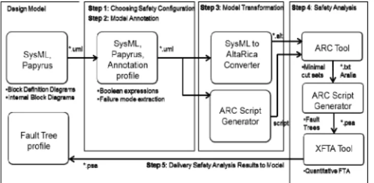
Fig. 1. The MSA methodology flow chart.
Generic MBSA flow described in the previous section may be quite sophisticated in the case of large hierarchical systems. Therefore we propose a flexible incremental MBSA approach meant to control the complexity of conducted analysis at the preliminary SA phase. This approach limits the depth of safety description of sub-systems depending on certain criteria defined across the analysis. MSA starts from the top down, whereas system failures are defined from the bottom up. The complexity of SA methods (which might be critical in the case of large systems) involved in this MSA flow is controlled by adjusting the SA depth.
Fig. 1 gives an overview of the MSA methodology. The following information is taken as input data: the SA recommendations taken from the IEC61508 [8] standard; the list of system hazards H and their criticality derived from the preliminary hazard analysis; the system architecture defined as a multi-level network of system components; the SA depth
depthSA or, in other words, the finest hierarchical level of
system architecture where SA is to be conducted; the set of
metrics M and their boundary values B defined in IEC61508 and used to evaluate a Safety Integrity Level (SIL) of a system and its components. As shows in Fig. 1 the MSA methodology includes several steps.
Step 1: Choosing Safety Configuration. A system is
analyzed by the safety engineer who defines the SA objectives, methods to be applied, safety evaluation metrics, as well as the finest architectural level sufficient to conduct SA (SA depth) in terms of time, cost, safety requirements, etc.
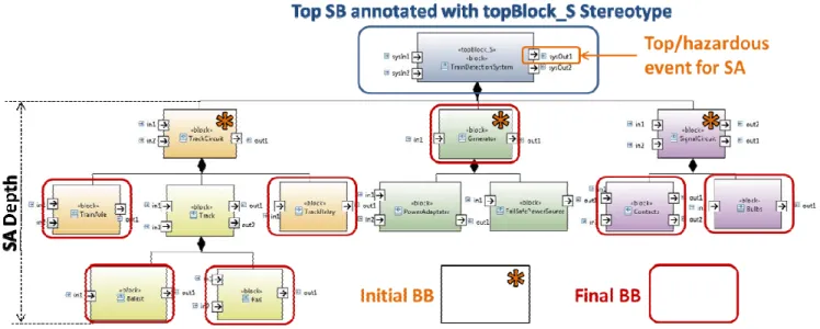
Fig. 2. The Multi-level Safety Analysis.
Step 2: Model Annotation. The system architecture is
expanded till the selected depthSA (as shown in Fig. 2) and components are annotated with the possible failure behavior represented as a set of failure modes. While defining failure modes of the system components, information on the possible hazards H is derived from the hazard analysis. Failure modes are introduced by either Boolean expressions (like, for example, in the HiP-HOPS [15] tool) or state machines. At the higher levels, the failure behavior of complex components is represented as a composition of failure modes defined for the components of the Finest SA Level (bounded by depthSA). In other words, system failures are described from the bottom up that guaranties the coherence of system failure behavior at different architectural levels.
Step 3: Model Transformation. This step is optional and
should be applied if SA flow related to the SA method chosen at Step 1 requires analysis of annotated model with the external tools. In this case, the failure states and events related to the failure modes are automatically extracted, and the model is converted into a formal language like AltaRica [16], SMV, etc. This model can be further analyzed using various SA methods such as FTA, FMEA, etc. recommended in IEC61508.
Step 4: Safety Analysis. SA starts from the granularity of
the top-level representation of a system as shown in Fig. 2. To assess system safety, we define a set of metrics M={m0,…mn}, as well as their boundary values B={bm0,…bmn}. These values are used as stop criteria during SA: if values of safety metrics estimated for a given component satisfy the stop criteria then SA is not conducted for this component; otherwise, a component is expanded for further SA. Such an iterative process continues until the granularity of the selected depthSA is reached for all components. If the results of SA reveal that some components overcome a required level of safety (measured in SIL or other metrics M defined during Step 1),
any of those components might be further analyzed using the same MSA methodology until the finest level of system hierarchy is reached. In this case, depthSA is updated and new information on component failure modes should be added into the model if needed. Such a selective fine-grained analysis can be a preliminary step for different methods dedicated to improve safety of large systems, for example SIL decomposition techniques, optimization algorithms, etc.
Step 5: Delivering SA Results to Model. To describe
system failures and then to derive the obtained SA results back into the modeling environment, we exploit the UML extension mechanism based on profiles. The use of UML profiles allows separation of different SA aspects related to various SA methods (FTA, FMEA, etc.) and types (qualitative and quantitative analysis). The principle of separation of concerns is widely used in engineering, including MDE, to address the ever growing complexity of system design.
The MSA methodology provides a possibility to control the granularity of SA through the system assessment process. The flexibility in choosing the sufficient scale of SA enables the safety engineer (i) to keep a desired level of precision during the SA process, (ii) to manage a complexity of SA methods applied, (iii) to reduce time required for SA. In addition, the model is annotated with failure behavior gradually and SA can be conducted even if not all the levels of system hierarchy have been annotated. The flexible SA depth and partial annotation are convenient while performing SA on large systems since they allow fast detection of safety-critical parts of a system with further focus on them in the early phases of development.
C. Sophia Framework
Sophia is a tool suite integrated within the Papyrus UML/SysML modeler. It supports MSA methodology and provides various MBSA services including FTA [17], FMEA [18], hazard analysis [7], requirement engineering, etc. In order to illustrate MSA methodology, hereafter we focus on the FTA method since it is often performed on large systems and enables global top-down SA. The standards [8][10]refer to FTA as a recommended technique for the preliminary SA phase of system life-cycle. FTA falls in two categories: qualitative and quantitative. The qualitative FTA aims to find all the minimal combinations of basic events (called minimal cut sets) resulting in the hazardous (or top) event. The quantitative FTA is used in probabilistic computation to assess the probability of the top event and minimal cut sets, to conduct sensibility and importance analysis, etc.
Fig. 3 shows the MSA flow and tool chain associated with the Sophia FTA module. The design model is obtained from a SysML description done with the Papyrus modeler. The design model should provide information on the overall functional architecture of a system. The SysML design model is analyzed by the safety engineer who defines depthSA, a set of safety evaluation metrics M to be assessed across FTA and their boundary values B. Then the model components are annotated with possible failure behavior via dedicated UML profile.
Fig. 3. Safety modeling flow for FTA.
Once the annotation has been done, the model is converted into AltaRica, a formal data flow language convenient to describe hierarchically structured safety-critical systems, for further FTA with formal tools such as ARC [19] and XFTA [20]. Sophia uses the ARC tool to compute FTs from the model described in AltaRica language and run qualitative FTA. ARC is an AltaRica compiler which uses constraints satisfaction techniques to compute sequences of events, minimal cut-sets, etc. Sophia automatically generates the ARC commands to compute minimal cut sets and to build FTs in the Open-PSA [21] format. Open-PSA format is the XML specific format that has been developed to describe and analyze large FTs. The quantitative FTA is conducted with the XFTA tool. XFTA performs various reliability analysis based on the probabilistic data associated with basic events of the FT including calculation of the probability of top event and minimal cut sets of the FT, sensitivity and importance analysis, SIL analysis, etc. In order to make results obtained from SA more representative, we display FTs in Sophia environment using dedicated FT profile based on the Open-PSA semantics.
To illustrate the proposed MSA methodology and Sophia framework as clearly as possible, we consider the example of a Train Detection System (TDS) and go through the safety modeling flow associated with our approach in the next section.
III. CASE STUDY
The MSA methodology described in the previous sections is validated by analyzing a Train Detection System (TDS) that has been studied in [22]. To reduce a probability of collision between trains, the track is split into sections and two trains must not occupy the same section of track at the same time. To ensure this, a TDS is installed on each section.
The system shown in Fig. 4 describes a situation when there is no train in the section. In this case generator G1 excites Relay core, which in turn attracts the Contacts, so that Signal Circuit for Green light is closed. Thus, Green light is on and Red light is off. When train arrives, the Track Circuit is short-cut through the Train Axle. Therefore, the Relay is not excited and Red light is on while Green light is off.
In this example, we consider a hazardous event: the Green
light turned on where a train is present. In other words, this
will be a top event of the tree.
A. Step 1: Choosing Safety Configuration
The design model of TDS was described in SysML. The architecture of TDS is represented in BDDs (Block Definition Diagrams) and IBDs (Internal Block Diagrams). The former shows hierarchical Block (type) organization (Fig. 6) while the latter describes interconnections between blocks. The TDS model includes four hierarchical levels, thirteen blocks, fourteen parts, two system input and output flow ports. We carry out SA at the three top levels of TDS architecture; consequently, the SA depth is three (depthSA = 3).
In this experiment, we choose FTA as a SA method and the probability of failure P as a safety metric to illustrate MSA methodology m=P, m є M. However, there is no restriction on the other SA methods recommended in IEC61508 or number and type of safety metrics. We assume that the boundary value of P used as a stop criterion for MSA should not exceed 4e-03 (b = 4e-03). In other words, if the probability of failure for a component is less than 4e-03 this component will be exempt from further SA.
B. Step2: Model Annotation
During this step, the SysML design model of TDS is annotated with failure behavior. While defining possible failures of TDS components, we take into account information on hazards H obtained from the hazard analysis with respect to IEC61508. The failure behavior is represented as a set of Boolean expressions showing how deviations in the block's outputs can be caused by internal failures (given as failure modes) of the block or possible deviations in the block's inputs. Only blocks of the finest architectural level (called basic blocks or BB) defined by depthSA are annotated with those expressions. Fig. 5 shows an example of such an annotation for the Contacts BB which belongs to the SignalCircuit block. The output deviation for the output out2 of the Contacts block is the following:
(in1 AND in2) AND (NOT Contacts_Failure_to_close AND NOT Contacts_Failure_InternalFailure) (1)
It means that the output out1 does not propagate failure behavior if (i) there are no failures Contacts_Failure_ to_close,
Contacts_Failure_InternalFailure of the block Contacts and
(ii) information on both the input flow port in1 and in2 is correct.
Fig. 5. Model annotation with failure behavior.
The annotation of TDS model is done by using a mechanism of UML profiles implemented in Papyrus. Sophia framework contains the annotation profile enabling to stereotype the output ports of BBs with deviation expressions. During the model translation process, the failure states and events related to BBs are automatically extracted from these expressions. Fig. 7 shows two stereotypes used to annotate input and output flow ports of BBs with information related to FTA. Deviation_expression property is used to enter deviation expressions; deviation_type defines a type of possible deviation including Absent, Omission, Commission and Error; fault_tree_computation shows if a corresponding FT must be generated for the given output. The latter property enables the safety engineer to analyze only a part of system architecture which might significantly shorten time and cost of FTA.
C. Step3: Model Transformation
At this step, the annotated SysML model of TDS is translated into a formal AltaRica model for further FTA conducted with the formal tools related to AltaRica. Although structures of SysML and AltaRica models (see [16] for semantic details) are indeed different, they have certain coherence: blocks and parts of SysML correspond roughly to nodes and sub-nodes of AltaRica. Thus SysML blocks can be translated into AltaRica nodes, and SysML parts can be translated into AltaRica instances of nodes. The latter are described within AltaRica nodes using tag sub. Interactions specified by SysML flow ports and connectors are also translated into AltaRica. Flow ports are represented as Boolean flow variables defined in the nodes. These variables can be set to true if information propagated via this port is correct, or to
false in the case of failure. Assertions are used to model the
connectors linking the ports. The assertions of variables related to flow ports help to realize failure propagation mechanism. TABLE I. lists the rules used for transformation of SysML model into AltaRica.
Fig. 6. The architecture of the Train Detection System described with SysML BDD.
Fig. 7. Port annotation stereotypes.
MSA methodology distinguishes two types of blocks constituting system architecture: BBs, the blocks of the finest level of system architecture defined by depthSA, and the sub-system blocks (SBs) combining BBs into higher level components. Thus, BB cannot be included into the hierarchy of another BB. They are used to model the internal failures of system components. SBs link BBs to their environment (other components, system environment) and help to propagate failures to the output chosen for FTA (and associated with the top event via annotation profile).
TABLE I. TRANSFORMATION RULES
Concept SysML AltaRica Description Component
type
System Block Node main System under analysis Component
/Prototype Block Part Field:sub Node components System Flow variable /Type /Direction FlowPort /Type /Direction Field: Flow /bool,integer, float,domain /In , Out System ports Connection of components
Connector Assertion Connection between components Output deviation expression Stereotyped FlowPort
Failure states and events, output
assertions
Component failure behavior
Fig. 8 shows the SysML/AltaRica transformation of BB Contacts. BB Contacts is translated into the node Contacts
starting with node and finishing with edon keywords. Input flow ports (in1 and in2) and output flow ports (out1 and out2) of Contacts are translated into four Boolean variables listed after keyword flow. Failure behavior detailed in the previous step (Fig. 5) as deviation Boolean expressions is described using failure states (defined by keyword state and initialized by keyword init) and events (defined by keyword event). Switching between states is defined with transitions (keyword
trans). Deviations of out1 and out2 are added as assertions
linking inputs in1 and in2, failure modes Contacts_failure_to_open, Contacts_failure_to_close, Contacts_InternalFailure and outputs out1 and out2.
Fig. 8. AltaRica node for the BB contacts.
Fig. 9 shows the transformation details of SB SignalCircuit. Parts of SignalCircuit are given as instances of corresponding nodes (one from node Contacts, and two from node Bulbs) indicated by keyword sub. Connectors are translated via
assertions (defined by keyword assert) linking input and output flows of SignalCircuit node and its sub-nodes.
Fig. 9. SysML IBD model of the block SignalCircuit and its translation into AltaRica.
In AltaRica a declaration of architecture should be made from the bottom up. Consequently, BB's must be declared first and then followed by SBs of the higher hierarchical levels until reaching the top SB. Sophia provides a simple algorithm to find the order of declaration of blocks in AltaRica model. Starting from BBs, Sophia searches for paths to the top SB and compiles the results (partials orders) into a global order of declaration (non-unique solution).
D. Step4: Safety Analysis
We validate MSA methodology described in the previous sections by applying FTA method implemented in Sophia (Fig. 3) to TDS. Sophia framework uses integrated ARC engine and ARC script generator to compute minimal cut sets of component failures violating a given top event. Trees obtained with FT generator are then analyzed by the integrated XFTA engine. Although in the present study, we compute the probability of occurrence of FT top event P (or probability of failure of TDS or its components), XFTA can produce other computations and provide a rich set of safety metrics. FT generation includes several steps. First, we obtain all possible minimal combinations of component failures violating a given top event. The list of minimal cut sets computed for TDS includes the following data:
trackcircuit.track.rightRail.Rail failure occurs trackcircuit.track.LocalBalast.Balast failure occurs trackcircuit.track.leftRail.Rail failure occurs trackcircuit.trainaxle.TrainAxle failure occurs trackcircuit.trainrelay.TrackRelay failure occurs TrackCircuitPowerSource.Generator failure occurs sysIn1. isAbsent
SignalCircuitPowerSource.Generator failure occurs sysIn2. isAbsent
signalcircuit.contacts.Contacts failure to open occurs signalcircuit.green.Bulbs failure occurs
signalcircuit.contacts.Contacts InternalFailure occurs
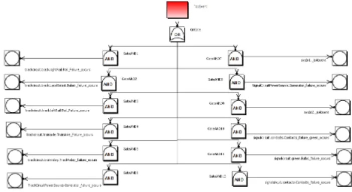
Second, we group these combinations, called minimal cut sets, in a tree structure as follows: (i) the events from each minimal cut set are considered as basic and grouped using AND gate; (ii) all the AND gates are then connected to the OR gate which, in turn, is linked to the top event.
Fig. 10. Automatically generated fault tree.
Fig. 10 shows the FT generated for TDS for the top event when "the Green light turned on where a train is present". Once FT has been built, we carry out a quantitative analysis to estimate safety metrics M. The probability of failure P is assessed from the statistical failure rates of appropriate BBs and compared with its boundary value b = 4e-03. If P ≤b then the appropriate block is not analyzed: its probability of failure is propagated and used (if needed) to assess other safety-critical component at finer levels of TDS architecture.
TABLE II. lists the quantitative FTA results obtained by following MSA methodology. Since depthSA = 3, we analyze three top architectural levels of TDS and run three iterations of MSA process.
Iteration 1. Starting from the top level of TDS architecture,
we estimate the probability of failure for the TrackCircuit (PTC=8e-02), SignalCircuit (PSC=5e-03) and Generator (PG==2e-03) blocks. We find that PTC and PSC are higher than chosen stop criterion boundary value of 4e-03, consequently, only TrackCircuit and SignalCircuit should be analyzed at the finer architectural levels. The further analysis of Generator can be omitted since its probability of failure is 2e-03 which is lower than the stop criterion.
TABLE II. FAULT TREE ANALYSIS:QUANTITATIVE RESULTS.
MSA Iteration Quant. FTA
Stop criterion: P ≤ 4e-03 P Stop #1 Block TrackCircuit 8e-02 × SignalSircuit 5e-03 × Generator 2e-03 9 #2 TrackCircuit.track 8e-02 × TrackCircuit.trainaxle 7e-05 9 TrackCircuit.trainrelay 4e-04 9 SignalSircuit.contacts 4.9e-03 × SignalSircuit.Bulbs 1e-04 9 Generator (2e-03) 9 #3 TrackCircuit.track.rightRail 3e-06 9 TrackCircuit.track.leftRail 3e-06 9 TrackCircuit.track.Balast 8e-02 × TrackCircuit.trainaxle (7e-05) 9 TrackCircuit.trainrelay (4e-04) 9 SignalSircuit.contacts (4.9e-03) × SignalSircuit.Bulbs (1e-04) 9 Generator (2e-03) 9
Iteration 2. TrackCircuit and SignalCircuit blocks are
TrainAxle, TrackRelay, and Bulbs. The Contacts block is not considered (the value of P is indicated as (P) in TABLE II. during this iteration because the value of PG has been propagated from the previous one. As shown in TABLE II. the probability of failure of Track and Contacts blocks do not satisfy stop criterion. However the Contacts block is BB, so the exploration stops for this branch and this block is marked as
non-conform to the stop criterion.
Iteration 3. The block Track is expanded and the analysis
is run again for the RightRail, LeftRail and Balast blocks. Block Balast is detected as the only non-conform block under Track SB but the analysis stops since we have reached the finest level of TDS architecture defined by SA depth.
The results given in TABLE II. show that MSA provides a convenient mechanism to identify safety-critical components (or blocks non-conform to stop criteria) and then focus on them to get more elaborated analysis results. Consequently, the use of the MSA methodology helps to manage system complexity at different architectural levels.
E. Step5: Propagation of Safety Analysis Results
To deliver the results obtained through the MSA process back to the SysML model context, we adopt UML profiles implemented in Papyrus. In UML, profiles extend and customize general language concepts. The use of several profiles specialized on particular aspects of SA gives an efficient facility to display or hide information in the SysML model. An important advantage of profiles is that they allow reuse of widely available UML/SysML means when displaying SA results in MDE environment. In the case of FTA, we extend a concept of the UML class and develop a profile which enables to display FTs (together with FTA results) in a graphical form as shown in Fig. 10. FTs may consist of basic, house and top events organized with AND and OR gates. The automatically generated FTs can be also represented in Open-PSA format, the XML specific format developed for describing complex FTs. Such FTs are displayed in the Sophia environment with the standard XML editor.
F. Scalability
The complexity of algorithm suggested in the scope of the MSA methodology is strongly linked to the number of levels in the system hierarchy and to the scalability of the formal verification tools. In the given case study we used ARC to generate minimal cut sets. If the number of potential failure modes increases, the risk of combinatorial explosion is higher. The TDS case study has demonstrated that the possibility to adjust the SA depth by partitioning SysML system architecture from the top down is a flexible instrument to control the number of failure modes and to decrease the risk of combinatorial explosion.
IV. RELATED WORKS AND DISCUSSION
In our research we focus on the preliminary phase of SA flow. One of the goals at this phase is to evaluate system architecture with respect to the list of possible hazards obtained from the hazard analysis. The system architecture can be evaluated using such methods as FTA [12], FMEA [13], event
tree analysis, etc. FTA and FMEA are complementary methods aiming to analyze propagation of faults through the system. FMEA is an inductive bottom up method used to analyze a system from component level up till system level. FTA, a deductive top-down method, does the opposite by defining a state on system level and verifying what can cause this on component level. Several methodologies and related tools have been developed to automate these classical SA methods. They can be summarized in three main steps: 1) description of failure behavior and its introduction in the system model; 2) safety analysis; 3) generation of results. However, they mostly lack two aspects:
• the elaborated process to bridge two domains: MDE and SA;
• the possibility to manage a complexity of SA methods applied to systems with multi-level hierarchy.
The methodology based on fault injection is introduced in [23] and further elaborated in [24][25][26]. According to this methodology, each component of the nominal system model is extended with a set of possible failure modes and then the extended system architecture is analyzed. The tools based on fault injection methodology (for example, FSAP/NuSMV [27]) translate an extended model into a state machine and then use formal verification algorithms to compute minimal cut sets and construct FTs or FMEA tables. In the case of complex systems, however, the application of this methodology may result in combinatorial explosion when the number of failure modes in state machines grows. Another group of methods exploit decision tables [22] to describe system failures. They are quite efficient for small and middle range systems but may require sophisticated tables for the systems with complex multi-level hierarchy. The methodology based on failure logic modeling uses Boolean expressions associated with the system components to model the possible propagation of failures through the system architecture. For example, the HiP-HOPS tool [15] generates FT and FMEA tables from system models (Matlab or EAST-ADL) enriched with output deviation specifications.
Although existing tools automate some steps of SA flow, their capabilities are limited in the case of complex systems. First, they lack convenient representation of the input system models. For example, SAML [28], FSAP / NuSMV or ARC tools use formal symbolic languages such as SMV, SAML or AltaRica to describe a system. This might require certain efforts from the SA engineer to formulate and enter the model in these formats. Second, they lack a convenient representation of SA results. In HiP-HOPS, for instance, safety annotations can be entered through a profile of the EAST-ADL extension of Papyrus, but there are no elaborated mechanisms to show the results of conducted SA in the MDE environment.
The analysis of literature shows that certain efforts have already been put into investigation of possible ways of SA application through the MDE process based on UML/SysML. For example, [1] describes a methodology based on SysML models for generating (semi-) automatically FMEA and FTA artefacts. In [3] the authors propose to incorporate FMEA flow into the functional design using SysML. Generation of static FTs from Maude specifications obtained from SysML models
is described in [4]. [29] introduces the SysML profile designed for modelling the safety-related concerns of a system and the supporting tools. Similar studies are also undertaken with DSLs such as AADL [5] or EAST-ADL [6]. Those approaches give a solid methodological support for MBSA by coupling MDA and SA, however, they do not provide mechanisms to manage a complexity of SA methods applied to systems with multi-level hierarchy. The MSA methodology proposed in this paper also uses SysML language and profiles to generate safety-related artefacts. In addition, MSA offers an incremental algorithm which helps to deal with hierarchical system gradually at several levels of architecture hierarchy.
V. CONCLUSION
In this paper, we introduce the MSA methodology and associated framework called Sophia that provide a support for SA engineers by bridging SA and MDE domains. The methodology describes incremental selective top-down analysis of hierarchical systems. This enables (i) a quick search of system components which are highly critical to safety requirements and (ii) further detailed analysis of those components. These characteristics make the MSA methodology suitable for the analysis of complex systems.
The Sophia framework adopts MSA approach. Sophia is an alternative to such SA tools as HiP-HOPS, Saml, FSAP/NuSMV. As opposed to these tools, it supports a common system model for system and safety engineers by using UML profile mechanisms in Papyrus. This allows integration of all information necessary to SA in the same system model, as well as customization of an interface to show different SA results within one uniform environment and reuse this information for further reliability studies.
The analysis of case study made with Sophia experimentally proved the ability of MSA to deal with multi-level system architectures and to manage the complexity of SA by focusing on safety-critical components.
REFERENCES [1] Eclipse modeling tool web page: eclipse.org/
[2] F. Mhenni, Nga Nguyen ; J.-Y. Choley, “Automatic fault tree generation from SysML system models,” IEEE/ASME International Conference on Advanced Intelligent Mechatronics (AIM), 2014, pp.715-720.
[3] P. David, V. Idasiak, F. Kratz, Reliability study of complex physical systems using sysml, Reliability Engineering & System Safety 95 (4) (2010) pp. 431 - 450.
[4] J. Xiang, K. Yanoo, Y. Maeno, K. Tadano, Automatic synthesis of static fault trees from system models, in: Proc. of the 5th International Conference on Secure Software Integration and Reliability Improvement (SSIRI), 2011, pp. 127-136.
[5] P. Feiler, D. Gluch, Model-Based Engineering with AADL: AnIntroduction to the SAE Architecture Analysis & Design Language,1st Edition, P.Ed Heg USA, 2012.
[6] P. Cuenot, D. Chen, S. Gerard, H. Lonn, M.-O. Reiser, D. Servat, R. Kolagari, M. Torngren, M. Weber, Towards improving dependability of automotive systems by using the east-adl architecture description language, in: R. Lemos, C. Gacek, A. Romanovsky (Eds.), Architecting Dependable Systems IV, Vol. 4615 of LNCS, Springer Berlin Heidelberg, 2007, pp. 39-65.
[7] D. Cancila, F. Terrier, F. Belmonte, H. Dubois, H. Espinoza, S. Gerard, A. Cucurru, Sophia: a modeling language for modelbased safety engineering, in: Proc. of the 2nd International Workshop On Model Based Architecting And Construction Of Embedded Systems, Denver, Colorado, USA, 2009, pp. 11-26.
[8] IEC 61508, Functional Safety of Electrical / Electronic/ Programmable Electronic Safety-related Systems, International Electrotechnical Commission (2000).
[9] ARP-4754, Certi_cation Considerations for Highly-Integrated Or Complex Aircraft Systems., Aerospace Recommended Practice (ARP) by Society of Automotive Engineers (SAE) (1996).
[10] ARP-4761, Guidelines and Methods for Conducting the Safety Assessment Process on Civil Airborne Systems and Equipment, Aerospace Recommended Practice (ARP) by Society of Automotive Engineers (SAE) (1996).
[11] IEC 61882, Hazard and operability studies(HAZOP studies) - Application guide, International Electrotechnical Commission (2001). [12] M. Stamatelatos, W. Vesely, J. Dugan, J. Fragola, J. M. III, J. Railsback,
Fault Tree Handbook with Aerospace Applications, NASA, 2002. [13] IEC 60812, Analysis techniques for system reliability – Procedure for
failure mode and effects analysis (FMEA), International Electrotechnical Commission (2006).
[14] Papyrus tool web page: eclipse.org/papyrus/
[15] M. Walker, L. Bottaci, Y. Papadopoulos, Compositional temporal fault tree analysis, in: F. Saglietti, N. Oster (Eds.), Computer Safety, Reliability, and Security, Vol. 4680 of LNCS, Springer Berlin Heidelberg, 2007, pp. 106-119.
[16] A. Arnold, A. Griffault, G. Point, A. Rauzy, The altarica language and its semantics, Fundamenta Informaticae 34 (2000) 109-124.
[17] N. Yakymets, S. Dhouib, H. Jaber, A. Lanusse, Model-driven safety assessment of robotic systems, in: Proc. of International Conference on Intelligent Robots and Systems (IROS), IEEE, 2013, pp. 1137-1142. [18] N.Yakymets, Y. Munoz Julho, A. Lanusse, « Sophia framework for
model-based safety analysis », Proc. of the 19th Congrès de Maîtrise des Risques et Sureté de Fonctionnement, Dijon, 2014, p. 71.
[19] ARC web page is altarica.labri.fr/forge/projects/arc/wiki [20] XFTA web page is lix.polytechnique.fr/~rauzy/xfta/xfta.htm [21] Open-PSA format web page is available at open-psa.org
[22] J. D. Andrews, J. J. Henry, A computerized fault tree construction methodology, Proc. of the Institution of Mechanical Engineers, Part E: Journal of Process Mechanical Engineering 211 (3), 1997, pp. 171-183. [23] O. Lisagor, J. A. McDermid, Towards a practicable process for
automated safety analysis, in: Proc. of the 24th International System Safety Conference (ISSC), 2006.
[24] M. Bozzano, et al., Esacs: an integrated methodology for design and safety analysis of complex systems, in: Proc. of the European Conference on Safety and Reliability (ESREL), 2003, maastricht, Netherlands.
[25] F. Ortmeier, W. Reif, G. Schellhorn, Deductive causeconsequence analysis (dcca), in: Proc of the 16th IFAC World Congres, 2005, pp. 1434-1434, czech Republic.
[26] A. Joshi, M. Heimdahl, Behavioral fault modeling for modelbased safety analysis, in: Proc. of the 10th IEEE High Assurance Systems Engineering Symposium, 2007, pp. 199-208.
[27] M. Bozzano, A. Villafiorita, The fsap/nusmv-sa safety analysis platform, International Journal on Software Tools for Technology Transfer 9, 2007, pp. 5-24.
[28] M. Gudemann, F. Ortmeier, A framework for qualitative and quantitative formal model-based safety analysis, Proc. of the 12th IEEE International Symposium on High-Assurance Systems Engineering (HASE), 2010, pp. 132-141.
[29] Geoffrey Biggs, Takeshi Sakamoto, Tetsuo Kotoku. A profile and tool for modelling safety information with design information in SysML. Software and System Modeling, Springer Berlin Heidelberg, 2014.
![Fig. 1 gives an overview of the MSA methodology. The following information is taken as input data: the SA recommendations taken from the IEC61508 [8] standard; the list of system hazards H and their criticality derived from the preliminary hazard analy](https://thumb-eu.123doks.com/thumbv2/123doknet/12919967.373260/3.918.71.388.438.716/overview-methodology-following-information-recommendations-standard-criticality-preliminary.webp)