Force delivery from a transpalatal arch for the correction of
unilateral first molar cross-bite
Peter Gollner*, Hans-Peter Bantleon**, and Bengt Ingervall*
'Department of Orthodontics, University of Bern, Switzerland, and "Department of Orthodontics, University of Vienna, Austria
SUMMARY The forces and moments delivered by prefabricated transpalatal arches of the makes Unitek, GAC, and Ormco were studied in laboratory experiments. The Unitek and GAC arches were made of steel, and the Ormco arch of beta-titanium alloy (TMA). Three types of activation were investigated: for bilateral expansion in a statically indeterminate system and for unilateral expansion in a statically determinate system with and without torque activation. In addition to the arch design, composition, and mode of activation, the influence of arch size and degree of activation were studied. It was found that activation for unilateral expansion with the inclusion of torque in the statically determinate system produced forces and moments suitable for the correction of a unilateral cross-bite.
Introduction
A unilateral lingual cross-bite of the upper first molar may be corrected by expansion with a transpalatal arch. In order to achieve a unilat-eral effect, the palatal arch should allow buccal movement of the molar in cross-bite while the contralateral molar ideally remains stationary. Such an ideal solution is not achievable solely by the use of a palatal arch, but would be approximated by the buccal tipping of the crown of the tooth in cross-bite against the buccal root torque of the contralateral molar. An expansive, horizontal force from the palatal arch would more rapidly effect the buccal crown tipping than the root movement of the anchor-age tooth. The force system implies a horizontal, expansive force which unavoidably acts on both teeth, and a moment for the buccal root torque of the anchorage tooth. Such a force system can be achieved in a statically indeterminate or in a statically determinate system.
In the statically indeterminate system, the palatal arch is inserted in the bracket or lingual sheath of both molars. A bracket is used with the recently described rectangular palatal arch (Burstone and Manhartsberger, 1988; Burstone, 1989), while a sheath is used with the Goshgarian type of palatal arch. Both types of attachment are characterized by a precise fit of the archwire in the attachment allowing no
rotation of the wire. In the statically indetermin-ate system, a difference in the moment-to-force ratio, i.e. an unequal amount of torque activa-tion, at the two sides will result in asymmetric tooth movement. The disadvantage of the static-ally indeterminate system is that it is very difficult to set up and that it can only be calibrated at the beginning of the treatment. When the teeth start to move the moments will change with unforeseen consequences.
The statically determinate system is much easier to calibrate. In principle, this system acts as a cantilever as the wire is only inserted in one attachment and on the other side is tied to the attachment with a ligature wire (single point contact). In the case of the unilateral cross-bite, the arch would only be inserted in the attach-ment of the anchorage tooth and would be tied to the attachment of the tooth in cross-bite. In practice, for the correction of a unilateral cross-bite, a statically determinate system would be simulated if the end of the rectangular wire on the side of the cross-bite was rounded off so that the wire could rotate in the attachment (theoret-ically no moment could develop). The same would be achieved by the Goshgarian arch if the wire on the side of the cross-bite was only single instead of the normal folded end. With this arrangement, the tooth in cross-bite could tip buccally while a moment and a force would be attained at the anchorage tooth. The
disadvant-412 P. GOLLNER ET AL. age of the described statically determinate
system is that vertical forces will develop to bal-ance the moment acting on the anchorage tooth. These forces will be extrusive of the tooth in cross-bite and intrusive of the anchorage tooth (Fig. 1).
The vertical distance between the attachment of the palatal arch and the assumed centre of resistance of a first molar is around 8 mm (Baldini, 1981). Bodily movement of a first molar, therefore, requires a moment-to-force ratio of 8. A larger ratio would be needed for buccal root torque. The correction of a unilat-eral cross-bite with a transpalatal arch in a statically determinate system would thus need a horizontal force and on the anchorage tooth a moment with a moment-to-force ratio of at least 8. When activating the arch for the hori-zontal force, it has to be realized that the torque will produce an additional expansive force when the arch is inserted in the attachments (Burstone and Koenig, 1981; Baldini and Luder, 1982).
The aims of the present investigation were, in laboratory experiments, to measure and com-pare the forces and moments delivered by three makes of prefabricated transpalatal arches when activated for bilateral expansion in a statically indeterminate system, and for unilateral expan-sion in a statically determinate system. After activation for unilateral expansion, the forces and moments achieved with and without torque activation were studied.
Materials and methods
Determination of the shapes and sizes of the arches
In order to determine the sizes of the palatal arches, the height of the palatal vault, and the
Figure 1 Forces and moments in a statically determinate system for the correction of a unilateral cross-bite.
distance between the upper first molars were measured on dental casts. The casts were made from alginate impressions of 35 children (17 boys and 18 girls), aged 6 years, 8 months to 15 years, 11 months (median age 10 years, 6 months) with a unilateral cross-bite of the upper first molar that was to be corrected with a transpalatal arch. The distance between the molars was measured across the palate and along the palatal surface to the next 0.5 mm with a flexible plastic ruler. The point of meas-urement on the molars corresponded to the location of the mesial end of a tube for the insertion of a palatal arch. The value measured was reduced by 4 mm to allow for a 1-2-mm distance between the palate and the archwire in clinical use. On the basis of the distribution of the distance between the right and left molars, it was decided that three sizes of palatal arch would meet the need in the vast majority of cases. The three intermolar distances were 39, 45, and 51 mm.
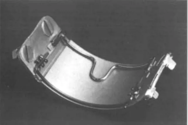
The maximum height of the palatal vault was measured on the casts with the method and with the special sliding calipers of Lundstrom (1948). The mean palatal height was calculated for the children with small, average, and large intermolar distances, respectively. Three stylized palatal curvatures were then determined and used to construct three metal templates (Fig. 2) onto which palatal tubes and attachments were welded parallel to each other at the small (size 1), average (size 2), and large (size 3) distances, respectively.
Types of arches
Prefabricated transpalatal arches of the makes Unitek (Unitek Corporation, Monrovia, California), GAC (GAC International Inc., Central Islip, New York), and Ormco (Sybron Corporation, Glendora, California) were studied in the experiments. The Unitek and GAC arches were round and made of steel with a diameter of 0.036 inch (0.91 mm). At the ends, the wire was bent back on itself, which made the combined cross-section rectangular to fit in the prefabricated (Unitek Corporation) rectan-gular tubes for the attachment of the arch. The Ormco arch was of beta-titanium alloy (TM A), it was square with a cross-section of 0.032 x 0.032 inches (0.8 x 0.8 mm) and was tied with a ligature in a Siamese Edgewise bracket (Ormco Corporation). The Unitek and GAC
Figure 2 Template and arches used in the study.
arches had a loop in the middle, while the Ormco arch was straight.
Mode of activation
Three types of activation were evaluated: 1. Bilateral, symmetrical expansion.
2. Attempted unilateral expansion. For this mode of action the bent-back part at one end of the arch on the Unitek and GAC arches was removed. The square Ormco arch wire was ground round on one side. This was done to allow the archwire to rotate in the tube or bracket on that side. This side will, henceforth, be called the alpha side. 3. Attempted unilateral expansion through the
torque effect (torque activation). The arch-wire was modified at one end as for unilateral expansion and, in addition, bent to a 10-mm vertical difference on the modified side between the tube or bracket and the end of the arch when the other end was inserted in the contralateral tube or bracket. With this activation, a torque effect on the non-modified side was achieved; this side will be called the beta side.
The activation for bilateral expansion and for torque activation was made with an increase of the arch width of 2, 3, and 4 mm, and for the steel arches also of 5 mm. With the mode for unilateral expansion, activation was made only to 2 mm arch width increase.
Measuring system •
The horizontal and vertical forces and the moments delivered by the activated arches and
by continuous deactivation were measured with the computer-based strain-gauge system of Bantleon (Droschl and Bantleon, 1991). In this measuring machine, the two ends of the arch were inserted into the palatal tubes (or brackets) fastened to the two movable clutches of the device. The clutches are sensored by strain-gauges which measure the forces and moments exerted on the clutches. The distance between the clutches could automatically be increased in steps of 0.5 mm by continuous recording by the computer of the forces and moments delivered. Measuring procedure
1. After having been formed on the template, the archwire was checked for passive state by insertion in the two attachments at the tem-plate alternately on the two sides. Thereafter, the intermolar width of the arch was increased 2-5 mm by pulling forces at the two ends.
2. The distance between the clutches of the measuring machine was adjusted to the inter-attachment width of the template and then increased by 2, 3, 4, and 5 mm, respectively. 3. The archwire was inserted into the clutches
and checked for passive state (maximum 10 g horizontal and/or vertical force). If the arch-wire was not passive, it was removed and adjusted by hand until passive.
4. The archwire was removed, after which the distance between the clutches was reduced to the inter-attachment width of the template and the archwire reinserted. The forces and moments were recorded in the initial active state and then during continuous deactiva-tion (automatically steered by the measuring machine).
This procedure was repeated twice for the same arch from step two. Each was thus meas-ured three times. The values from the first recording were not used in the analysis because this recording was equivalent to a trial activa-tion which changes the force properties of the metal. The values from the second and third recordings were averaged.
For the recording with torque activation after step 3 above, one end of the arch was adjusted to be at a 10 mm vertical distance from the clutch before the insertion in the attachment. This is equivalent to a 19-degree torque activa-tion for the small arch size and to 17 degrees for the largest.
414 P. GOLLNER ET AL.
Results
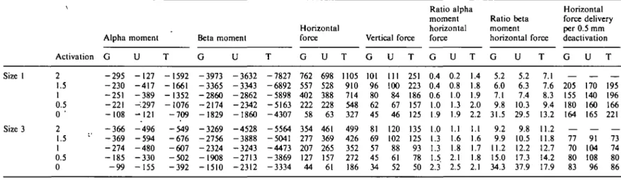
Comparison of the forces and moments produced by the different modes of use and makes of arches The results of the measurements of the mechan-ical properties of the medium size of the three makes of arches with the three different modes of activation are given in Table 1.
With bilateral expansion, all three arches (G, U, and T) delivered small alpha and beta moments (Table 1). The moments with unilat-eral expansion were, especially for the steel arches, greater than with bilateral expansion. With the steel arches, the direction of the alpha and beta moments also differed. The torque activation did not markedly change the alpha moments of the steel arches compared with those during unilateral expansion, but caused an increase of the TMA arch alpha moments. Whereas the alpha moments of the steel arches after unilateral and torque activation were posit-ive, these moments were negative for the TMA arch. For all three types of arch, the torque activation gave rise to a considerable increase of the beta moments compared with those pro-duced by the other types of activation. The beta moments after torque activation had a consist-ent direction and were almost idconsist-entical for the two steel arches, but about twice as large for the TMA arch.
The horizontal forces were somewhat lower after bi- than after unilateral expansion, but similar for the three types of arches. The torque activation gave rise to greater horizontal forces than the other two types of activation, especially for the TMA arch. The greatest horizontal forces after torque activation were recorded for the TMA arch while the steel arches differed only moderately, with the lowest forces for the GAC arch (Table 1, Fig. 3). The horizontal force delivery during deactivation was remarkably constant and similar for all three types of arches. Because of the smaller horizontal forces after bilateral activation, the force delivery was lowest for this type of activation, but only moderately larger for torque than for bilateral activation (Table 1).
The vertical forces were generally small during bi- and unilateral expansion. Torque activation increased the vertical forces, especi-ally those from the TMA arch. Torque activa-tion thus resulted in greater vertical forces from the TMA arch than those from the steel arches, which were of the same magnitude (Table 1).
The alpha moment to horizontal force ratios were small for all three types of activation. The beta moment to horizontal force ratios were likewise small after bi- and unilateral expansion, but increased considerably for all three types of arches after torque activation (Table 1). Influence of the arch size on the mechanical properties after torque activation
The mechanical properties of the small and large sizes of arches after torque activation are given in Table 2.
The alpha moments delivered by the steel arches varied with the arch size. The size 1 steel arches delivered small negative alpha moments. The size 3 steel arches also delivered negative, but somewhat larger moments. The size 2 steel arches delivered fairly large positive moments. The alpha moments from the TMA arch were consistently negative and decreased with increasing arch size (Table 2).
The beta moments of the steel arches were very similar for the size 1 and size 2 arches and between the two arches. The beta moments of the size 3 Unitek arch were somewhat larger than those of the two smaller sizes while the opposite was true for the GAC arch. The beta moments of the TMA arch were likewise very similar for sizes 1 and 2, but smaller for the size 3 arch. The moments from the TMA arch were for all arch sizes greater than those from the steel arches (Table 2).
The horizontal forces from all three arches decreased with increasing size. The forces were for all three arch sizes similar in magnitude for the two steel arches and smaller than from the TMA arch (Table 2). The horizontal force deliv-ery during deactivation was for all sizes similar between the three arch types and decreased with increasing arch size.
The vertical forces were for all arch sizes greater for the TMA arch than for the two steel arches. For the TMA arch and less regularly for the GAC arch, these forces decreased with increasing arch size. The vertical forces from the Unitek arch were similar in magnitude for the arch sizes 1 and 3, but smaller for size 2 (Table 2, Fig. 4).
The alpha moment-to-force ratios were small for all three types and sizes of arches and did not vary much between the types or sizes of the arches (Table 2). The beta moment-to-force ratios were substantially larger than the alpha
Table 1 Moments (in g mm) and forces (in g), as well as moment-to-force ratios and horizontal force/deflection rates for the GAC (G), Unitek (U),
and TMA (T) arches of size 2 (deactivation every 0.5 mm).
Horizontal
Ratio alpha " Ratio beta force delivery moment moment per 0.5 mm Alpha moment Beta moment Horizontal force Vertical force horizontal force horizontal force deactivation
Bilateral expansion Unilateral expansion Torque activation Activation 2 1.5 1 0.5 0 2 1.5 1 0.5 0 2 1.5 1 0.5 0 G -145 -116 -137 -255 - 2 8 4 1019 340 138 31 -8 1635 931 215 -139 -179 U 5 -113 - 1 4 2 -112 -143 2170 1491 948 702 345 1924 1433 887 500 76 T 113 -145 -94 -37 25 -369 -412 -285 -185 -175 -1136 -1333 -1260 -1136 -1054 G -597 - 2 7 0 -68 -65 -51 -1126 -627 - 2 8 0 -96 -33 -4274 -3641 -3041 -2547 -2122 U 93 146 191 197 160 -1547 -1078 - 6 3 0 -271 -74 -4158 -3606 -3093 -2532 -1989 T 31 161 199 142 96 -632 -135 -89 68 93 -7805 -7119 -6463 -5762 -5077 G 321 222 134 54 -27 386 250 135 44 -8 599 453 302 179 75 U 262 195 121 59 -14 448 335 222 125 20 636 528 407 289 153 T 269 171 91 17 -34 329 234 150 79 -7 817 700 602 490 359 G 13 8 1 1 1 4 8 5 2 1 69 69 72 67 55 U -4 -2 -3 -5 -5 -19 -15 2 -16 -12 54 50 50 49 41 T -9 -4 -4 -2 -2 25 14 5 3 1 213 197 177 157 137 G 0.5 0.5 1.0 4.7 10.5 2.6 1.4 1.0 0.7 1.0 2.7 2.1 0.7 0.8 2.4 U 0.0 0.6 1.2 1.9 10.2 4.8 4.5 4.3 5.6 17.3 3.0 2.7 2.2 1.7 0.5 T 0.4 0.9 1.0 2.2 0.7 1.1 1.8 1.9 2.3 2.5 1.4 1.9 2.1 2.3 2.9 G 1.9 1.2 0.5 1.2 1.9 2.9 2.5 2.1 2.2 4.1 7.1 8.0 10.1 14.2 28.3 U 0.4 0.7 1.6 3.3 11.4 3.5 3.2 2.8 2.2 3.7 6.5 6.8 7.6 8.8 3.0 T 0.1 0.9 2.2 8.4 2.8 1.9 0.6 0.6 0.9 13.3 9.6 10.2 10.7 11.8 14.1 G 99 88 80 81 — 136 115 91 52 146 151 123 104 U 67 74 62 73 — 113 113 103 105 108 121 118 136 T 98 80 74 51 — 95 84 71 86 117 98 112 131 n m O m r < m ps •< •n o s H >
I
>
r po O X416 P . GOLLNER ET AL. Force ( g ) 600T BILATERAL 2 600 T 1 0.5 0 Activation ( m m ) UNILATERAL
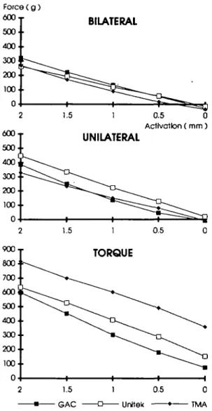
Figure 3 Horizontal forces delivered by the size 2 arches
of the three makes with the three different modes of activation.
moment-to-force ratios and for all three types of arches generally increased with increasing arch size. The beta moment-to-force ratios were as a rule somewhat larger for the TMA arch than for the steel arches.
Influence of increased horizontal activation on the horizontal force delivery
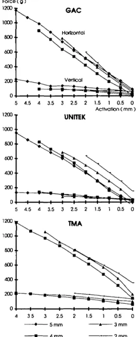
The relationship between the horizontal forces measured and the degree of horizontal activa-tion after constant (10 mm) torque activaactiva-tion is shown in Fig. 5. The horizontal force delivery increased linearly up to 5 mm horizontal
activa-tion, which was the largest activation tested. With 4 mm activation, the GAC, Unitek, and TMA arches delivered approximately 890, 830, and 1190 g horizontal force, respectively. With 3 mm activation the corresponding values were 790, 690, and 1060 g, respectively.
Constancy of clinical activation
In this study the archwires were checked to assure passivity in the deactivated state before the measurements began (see point 3, measuring procedure). This is, of course, not possible in clinical practice. In order to evaluate the size of the variation when wires are activated without access to the control possibilities of the measur-ing machine, 10 wires were activated by hand and measured. This test was done with 10 Unitek wires, five of which were activated by examiner A and five by examiner B. Two milli-meters horizontal activation combined with
10 mm vertical difference (torque activation) was examined. Before mounting the archwire in the machine, the degree of activation was checked by the examiner by means of a ruler in order to obtain the best possible accuracy. The horizontal forces from the 10 arches after 2 mm activation varied from 479 to 742 g (median 637 g) and the vertical forces from 58 to 174 g (median 152 g). The alpha moment to horizontal force ratios and beta moment to horizontal force ratios delivered by the 10 arches are shown in Fig. 6.
Discussion
The comparison of the three modes of activation of the size 2 arch (Table 1) showed that the prerequisites for a unilateral effect were achieved with the GAC and TMA arches. These arches delivered a moment-to-force ratio of 8 or more on the beta (anchorage) side on torque activa-tion. All arches had a low alpha moment-to-force ratio on torque activation. During unilat-eral expansion and after torque activation, fairly large alpha moments were delivered. These moments are undesirable and must be a result of friction between the archwire and the attach-ment. Therefore, great care should be taken during the adjustment of this side of the arch in order to keep the friction as low as possible. The increase of the horizontal forces at the same degree of activation when the archwire was activated for torque (compare unilateral
Table 2 Moments (in g mm) and forces (in g), as well as moment-to-force ratios and horizontal force/deflection rates for the GAC (G), Unitek (U),
and TM A (T) arches of sizes 1 and 3 by torque activation (deactivation every 0.5 i
73 O m D en r < m 73 >< 73 O s 73 Size 1 Size 3 Activation 2 1.5 1 0.5 0 ' 2 1.5 " 1 0.5 0 Alpha G - 2 9 5 - 2 3 0 - 2 5 1 - 2 2 1 - 1 0 8 - 3 6 6 - 3 6 9 - 2 7 4 - 1 8 5 - 9 9 moment U - 1 2 7 - 4 1 7 - 3 8 9 -:297 - 1 2 1 - 4 9 6 - 5 9 4 - 4 8 0 - 3 3 0 - 1 5 5 T - 1 5 9 2 - 1 6 6 1 - 1 3 5 2 - 1 0 7 6 - 7 0 9 - 5 4 9 - 6 7 6 - 6 0 7 - 5 0 2 - 3 9 2 Beta moment G - 3 9 7 3 - 3 3 6 5 - 2 8 6 0 - 2 1 7 4 - 1 8 2 9 - 3 2 6 9 - 2 7 5 6 - 2 3 2 4 - 1 9 0 8 - 1 5 1 0 U - 3 6 3 2 - 3 3 4 3 - 2 8 6 2 - 2 3 4 2 - 1 8 6 0 - 4 5 2 8 - 3 8 8 8 - 3 2 4 3 - 2 7 1 3 - 2 3 1 2 T - 7 8 2 7 - 6 8 9 2 - 5 8 9 8 - 5 1 6 3 - 4 3 0 7 - 5 5 6 4 - 5 0 4 1 - 4 4 7 3 - 3 8 6 9 - 3 3 3 4 Horizontal force G 762 557 402 222 58 354 277 207 127 44 U 698 528 388 228 63 461 369 265 157 61 T 1105 910 714 548 327 499 426 352 272 186 Vertical force G 101 96 80 62 45 81 69 57 45 34 U HI 100 84 67 46 120 102 88 61 52 T 251 223 186 157 125 135 125 93 78 50 Ratio alpha moment horizontal force G 0.4 0.4 0.6 1.0 1.9 1.0 1.3 1.3 1.5 2.3 U 0.2 0.8 1.0 1.3 1.9 1.1 1.6 1.8 2.1 2.5 1 T 1.4 1.8 1.9 2.0 2.2 1.1 1.6 1.7 1.8 2.1 Ratio beta moment horizontal G 5.2 6.0 7.1 9.8 31.5 9.2 9.9 11.2 15.0 34.3 U 5.2 6.3 7.4 10.3 29.5 9.8 10.5 12.2 17.3 37.9 force T 7.1 7.6 8.3 9.4 13.2 11.2 11.8 12.7 14.2 17.9 Horizontal force: delivery per 0.5 mm deactivation G 205 155 180 164 77 70 80 83 U 170 140 160 165 91 104 108 96 T 195 1% 166 221 73 74 80 86 c r 73 o X
418 P. GOLLNER ET AL.
Force (g) 250
Force ( g )
SIZE 1
Figure 4 Vertical forces delivered by sizes 1-3 of the three
makes of arches after torque activation.
and torque activation) illustrates the additional horizontal force that results from the torque. It was found in a separate measurement that with the size 2 arch the torque activation without horizontal activation gave rise to a horizontal force equivalent to 1 mm horizontal activation by the TMA arch and to 0.4 mm by the steel arches. That the unilateral expansive effect is
£\XJ • 000- 800- 600- 400-200' 0-. GAC " \ X Horizontal — • — _ ^ Vertical ^ » O ^ k i i i i—i T 7 T= =t= :^l 5 4.5 4 3.5 3 2.5 2 1.5 1 0.5 0 Activation ( m m ) UNITEK 5 4.5 4 3.5 3 Z5 2 1.5 1 0.5 0 TMA 2 m m Figure 5 Horizontal and vertical forces at different degrees of horizontal activation of the size 2 arches of the different makes after torque activation.
obtained at the cost of vertical forces is clearly evident from the table. Because of the large beta moments delivered by the TMA arch, the vertical forces were largest for this arch. The extrusive force acting on the tooth in cross-bite will increase the buccal crown tipping of this
M/F 2 0T 1 6 ' • 12. • 1 0.5 0 Activation ( m m )
Figure 6 Moment-to-force ratios delivered by 10 size 2 Unitek arches when activated for torque and 2 mm expan-sion by two examiners.
tooth. The reason is that the point of force application is palatal to the centre of resistance of the tooth. An outward tipping moment there-fore arises. This is a favourable effect for the correction of the cross-bite. Likewise, the intrus-ive force on the anchorage tooth will result in an additional buccal root torque of this tooth.
The horizontal forces delivered after bi- and unilateral activation were of the same magni-tude for all three types of arch. Theoretically, the TMA arch should have produced lower forces than the steel arches because the modulus of elasticity of beta-titanium is only 42 per cent of that of steel (Burstone, 1981). The explana-tion is the loop incorporated in the middle of the steel arches, which increases the length of the wire by approximately 10 mm. In practice, therefore, the straight TMA arch and the looped steel arches of the smallest arch size deliver the same horizontal force at the same degree of activation. With the size 2 and 3 arches, the steel arches deliver by calculation 4 and 8 per cent more force, respectively, than the TMA arch. The reason is that with the larger arches the relative increase of the arch length by the loop is smaller because the loop is of the same size for all arches. The greater beta moments and vertical forces after torque activation delivered by the TMA arch than by the steel arches can also be explained by the smaller effective length of the TMA arch. In addition, the loop of the steel arches not only increases the length of the arch, but also gives the wire
flexibility in the horizontal dimension. Therefore, less torque activation should be used with the TMA arch to achieve a similar force system as with the steel arches. Separate meas-urements showed that with the size 2 arch 5 mm torque activation produced similar moments and forces to 10 mm activation with the steel arches.
The size of the arch had a marked influence on the forces and moments delivered. Much greater horizontal forces were delivered by the smallest than by the largest arch size (Table 2). The smaller horizontal forces delivered by the size 3 arch favourably influenced the beta moment-to-force ratio. With this arch size, all three makes of arches demonstrated desirable beta moment-to-force ratios. This was in con-trast to the size 1 arch, where none of the arches with the larger degrees of activation had a beta moment-to-force ratio in the desired range. The clinical implication is that small arch sizes should be less activated horizontally.
An increase of the horizontal activation up to 5 mm resulted in a linear increase of the horizontal force delivery. There was no sign of a permanent set of the archwires. While the degree of torque activation was kept constant, the beta moment-to-force ratio decreased with increasing horizontal activation. All of the size 2 arches had a beta moment-to-force ratio below the desirable range with horizontal activation above 2 mm (not shown in the results). Activation of more than 2 mm thus seems to be counterproductive. The question of how much horizontal force is biologically favourable or acceptable is beyond the scope of this investi-gation. Expansive forces from a palatal arch have been shown to produce not only tooth movement but also widening of the palatal suture (Harberson and Myers, 1978; Bell and LeCompte, 1981; Frank and Engel, 1982). Although the horizontal forces delivered by the arches seem high, greater forces are certainly used during rapid maxillary expansion (Chaconas and Caputo, 1982).
The fact that the activation of the arches as carried out under clinical conditions produced fairly uniform results is encouraging. This shows that, with care, it is possible to approximate the standardization of the forces and moments that can be achieved in laboratory experiments.
The study has shown that the use of a trans-palatal arch for the correction of a unilateral
420 P. GOLLNER ET AL. cross-bite meets the requirements that can be
theoretically formulated for a statically deter-minate system. A study of the effects obtainable in clinical use is under way. One of the interes-ting questions is the effect of the vertical forces. It is not known to what extent these are bal-anced by the forces from occlusion or if the vertical effects are equilibrated during the ver-tical growth of the face.
Address for correspondence Dr P. Gollner
Klinik fur Kieferorthopadie Freiburgstrasse 7
CH-3010 Bern Switzerland
References
Baldini G 1981 Apparative Messung der durch die Torquebiegungen am Palatinalbogen entstehenden Drehmomente und der durch die Torqueapplikation ent-stehenden expansiven Kraft. Informationen aus Orthodontic und Kieferorthop5die 3: 11-22
Baldini G, Luder H U 1982 Influence of arch shape on the transverse effects of transpalatal arches of the Goshgarian type during application of buccal root torque. American Journal of Orthodontics 81: 202-208
Bell R A, LeCompte E J 1981 The effects of maxillary expansion using a quadhelix appliance during the decidu-ous and mixed dentitions. American Journal of Orthodontics 79: 152-161
Burstone C J 1981 Variable-modulus orthodontics. American Journal of Orthodontics 80: 1-16
Burstone C J 1989 Precision lingual arches. Active applica-tions. Journal of Clinical Orthodontics 23: 101-109 Burstone C J, Koenig H A 1981 Precision adjustment of
the transpalatal lingual arch: Computer arch form prede-termined. American Journal of Orthodontics 79: 115-133 Burstone C J, Manhartsberger C 1988 Precision lingual arches. Passive applications. Journal of Clinical Orthodontics 22: 444-451
Chaconas S R, Caputo A A 1982 Observation of orthopedic force distribution produced by maxillary orthodontic appliances. American Journal of Orthodontics 82: 492-501
Droschl H, Bantleon H P 1991 Klinische Relevanz der Materialforschung und Mechanik. Symposion der Deutschen Gesellschaft fur Kieferorthopadie: Bad Homburg, 1989. Urban and Vogel, MQnchen
Frank S W, Engel G A 1982 The effects of maxillary quad-helix appliance expansion on cephalometric measure-ments in growing orthodontic patients. American Journal of Orthodontics 81: 378-389
Harberson V A, Myers D R 1978 Midpalatal suture opening during functional posterior cross-bite correction. American Journal of Orthodontics 74: 310-313 Lundstrom A 1948 Tooth size and occlusion in twins.