Publisher’s version / Version de l'éditeur:
Vous avez des questions? Nous pouvons vous aider. Pour communiquer directement avec un auteur, consultez la
première page de la revue dans laquelle son article a été publié afin de trouver ses coordonnées. Si vous n’arrivez pas à les repérer, communiquez avec nous à [email protected].
Questions? Contact the NRC Publications Archive team at
[email protected]. If you wish to email the authors directly, please see the first page of the publication for their contact information.
https://publications-cnrc.canada.ca/fra/droits
L’accès à ce site Web et l’utilisation de son contenu sont assujettis aux conditions présentées dans le site LISEZ CES CONDITIONS ATTENTIVEMENT AVANT D’UTILISER CE SITE WEB.
Internal Report (National Research Council of Canada. Division of Building Research), 1960-07-01
READ THESE TERMS AND CONDITIONS CAREFULLY BEFORE USING THIS WEBSITE.
https://nrc-publications.canada.ca/eng/copyright
NRC Publications Archive Record / Notice des Archives des publications du CNRC : https://nrc-publications.canada.ca/eng/view/object/?id=a4c0fb75-c80e-4ce2-bc6a-6e384d9589fa https://publications-cnrc.canada.ca/fra/voir/objet/?id=a4c0fb75-c80e-4ce2-bc6a-6e384d9589fa
NRC Publications Archive
Archives des publications du CNRC
For the publisher’s version, please access the DOI link below./ Pour consulter la version de l’éditeur, utilisez le lien DOI ci-dessous.
https://doi.org/10.4224/20338192
Access and use of this website and the material on it are subject to the Terms and Conditions set forth at
Air infiltration, surface temperature and condensation studies on two aluminum windows
NATIONAL RESEARCH COUNCIL CANADA
DIVISION OF BUILDING RESEARCH
AIR INFILTRATION, SURFACE TEMPERATURE9AND
CONDENSATION STUDIES ON TWO ALUMINUM WINDOWS by
E&S& Nowak and A&Go Wilson
Internal Report
No& 199
of the
Division of Building Research
OTTAWA July 1960
PREFACE
The Division is privileged to receive the co-operation of manufacturers in studying and reporting upon the performance of proprietary bUilding components when the information to be
gained is being sought for research purposes. A study of the
performance of window units is being carried out which of necessity
involves the examination of a variety of window designs. The
manufacturer in the case now reported offered samples of particular
ゥョエ・イ・ウセ since they had been designed to provide somewhat more
resistance to heat flow through the metal frames than is customary. These studies are continuing.
The authors are both mechanical engineers,
Mr.
Wilsonbeing Head of the Building Services Section of the Division;
Mr.
Nowak, formerly a Research Officer of that section is atpresent taking post-graduate studies at IUrdue University in the United States.
Ottawa
I II III
IV
V TABLE OF CONTENTSDesc+iption of Windows and Test Installation Air Infiltration Tests
Temperature Measurements Condensation Tests
Summary and Conclusions
Page 1 2 3 10 11
AIR infiltrationセ SURFACE teセセeratureセand
CONDENSATION STUDIES ON TWO ALUMINUM WINDOWS
by
This report covers laboratory measurements of
temperaturep condensation and air infiltration on manufactureris
demonstration samples of an aluminum double double-hung window and an aluminum casement window intended for residential or
commercial bUildingsc The frames of both consisted of two
aluminum sections separated by a wood spacer to eliminate
continuous metal paths from inside to outsideo The sash of the
casement window was Similarly 」ッョウエイオ」エ・、セ but with a
hard-board spacer. Special consideration is given to the adequacy
of these "thermal breaksll in terms of metal and glass surface エ・ュー・イ。エオイ・ウセ
I. DESCRIPTION OF WINDOWS AND TEST INSTALLATION
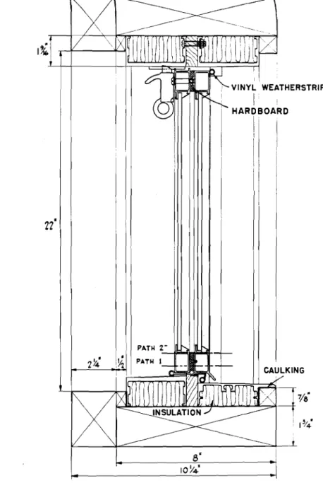
The details of the two windows used in this study are given
in Figs. 1 and 2. The window frames of both consisted of two
aluminum sections separated by a 9/16=in. thick wood spacer.
The casement sash of the casement window consisted of two aluminum
sections separated by a QOTセゥョN thick hard=board spacer. The
spacers served as "thermal breaks"o
During all of the tests the windows were contained in a
Tセ by8=ft. insulated wood-frame wall panel installed in the
Building Services cold room. Details of the wall panel are
given in Fig.
3.
The details at the head and sills of the twowindows as installed in the wall panel are given in Figse 1 and 2,
Figure
4
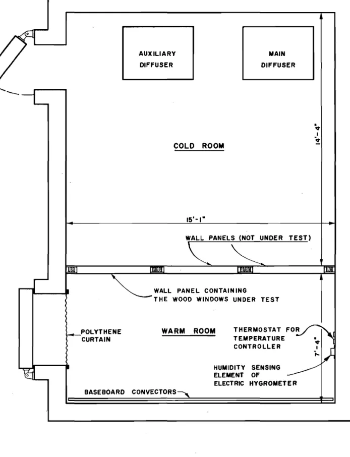
shows the wall panel with respect to the testequipment in the, cold room. The wall panel formed part of
the partition which divided the cold room into large and small
compartments. In this report the large and small compartments
are termed cold room and warm room9 respectively< During the
temperature measurement and condensation tests9 temperature
and humidity conditions intended to simulate those found Lnsi.de
and outside of buildings were provided in the warm and cold イッッュウセ
respectively. .
The necessary cooling in the cold room was provided by
evaporation coils and the electric reheat elements. Air was circulated over the cOils and the reheaters by a fano . The air temperature variation at any point in the cold room did not
exceed ±Oc25 F degrees The ヲャッッイセエッM」・ゥャゥョァ air temperature
gradient did not exceed 1 degree, These conditions were ュ。ゥョセ
tained by the use of a modulating temperature controller which
regulated the electrical input into the reheaters with the refrigeration system operating continuouslyo
The cold room air moved in a downward direction over
the outer surfaces of the two windowsc The air velocity was
not uniform and was approximately 6 and
4
mph over the outersurfaces of the double 、ッオ「ャ・セィオョァ and casement キゥョ、ッキセ イ・ウー・」エゥカ・ャケセ
The warm room was heated by the gravity baseboard
convectors located approximately
9
ino from the floor o Theelectrical input to the convectors was regulated by a
temperature controller o The air temperature at a level of
Tセ ft from the floor in the centre of the warm room was ュ。ゥョセ
tained at 700F to within
±
1 degreeoA humidifying and a dehumidifying system operated by an electric hygrometer of the contact meter type maintained
the desired relative humidities in the room o Wet and dry
bulb temperatures were observed to within *0025 F degrees with an aspirating psychrometer at a point in the room near the
thermostat locationo The humidities9 determined from the
observations of wet and dry bulb temperatures9 were maintained
within
±
1 per cent oII AIR INFILTRATION TESTS
These tests were carried out to determine the over=all
air leakage characteristics of the two windows. The procedure
followed was to seal one side of the window into an air=tight compartment and either introduce or withdraw air at a rate such as to maintain a given pressure difference across the window o
The air conditions on both sides of the window were maintained
at approximately 72°F and 50 per cent relative humidity0
A calibrated variable area flowmeter measured the air
flow to or from the compartment to within 0.13 cfme The
pressure difference across the window was measured with a Betz micromanometer having a sensitivity of 0 0001 ino of water o
The air flow to or from the compartment was in excess of the air flow through the window by the amount of extraneous
セ 3 =
results reported here have been corrected for this. In
addition the results obtained under test conditions have been converted to air flow rates which would occur with air at a
standard density of 00075 pcf and an air temperature of 70oFo
The conversions obtained by test9 are based on the flow equations
for the window 0
The air leakage characteristics for the two windows are
given in Figo 5. The differences between the air flows obtained
with inside pressure greater than outside and the air flows obtained with inside pressure less than outside were small and
in most cases were within the limits of error. In view of エィゥウセ
a best line was drawn through the test results.
The air infiltration rates for the double double-hung and casement windows at a pressure difference equivalent to the dynamic head of a 25,-mph wind (0.301 ina of water) are 1.2
and 0 06 cfm per foot of sash 」イ。」ォセイ・ウー・」エゥカ・ャケN The Aluminum
Window Manufacturers Association in their specifications suggest a maximum air infiltration rate for double double-hung and
casement windows of 0.5 afm per foot of sash crack at a pressure difference corresponding to a 25-mph wind.
III TEMPERATURE MEASUREMENTS
The temperatures of the interior and exterior window
surfaces were measured at various inside-outside air temperature
differences. All of the temperatures were measured with B.S. NoD
30 gauge thermocouples in conjunction with a sensitive electronic indicator.
A vertical string of thermocouples installed in the centre of the warm room measured the variation in air temperature from
the ceiling to the flooro A second string of thermocouples
measured the variation in air temperature in the cold room o
The thermocouples used in the measurement of air temperatures were unshielded.
The interior and exterior aluminum surfaces were ゥョセ
strumented with thermocouples as shown in Figa 6(a)0 The twisted
soldered part formed the thermojunction and approximately ャセ
ina of the lead Wires were embedded in horizontal shallow slotsc
ilie thermocouples were held in direct contact with the aluminum surfaces by an adhesiveo
The interior and exterior glass surfaces were instrumented
wi th butrt-wel de d thermocouples shown in Fig. 6,(b). These
4
-a bl-ack pl-astic t-ape -and -att-ached to the exterior gl-ass
surfaces with cellulose tape. Cellulose tape was used because
of its better adherence at low temperatures.
During the first series of cold room tests the de-humidification system was operated continuously to minimize
surface condensation. The warm room relative humidity was
lowered from approximately 50 to 10 per cent in the course
of this test. There was no condensation on the interior
aluminum and glass surfaces during these temperature ュ・。ウオイ・セ
ments, although it occurred on the aluminum surfaces between the panes and on the inside surface of the outer pane at
the first cold room temperature of 20oP,
Tables 1 and 2 give the results of the temperature
measurements. lli.ere are appreciable differences between
the inside surface temperatures of the aluminum at the top
and bottom of the windows. These differences are particularly
notable for the frame of the double double-hung window and the sash of the casement window.
There was no significant variation in inside or outside air temperature over the height of the windows and the surface-to-surface thermal conductances of the components of both the frames and sash were the same at top and bottom. hッキ・カ・セ
there are other factors affecting the inside surface temperatures that might contribute to the differences observed between
top and bottom surfaces. One of these is relative resistance
to heat exchange at inside and outside surfaces which depends on the amount of exposed surface and the "film coefficientlt
,
this in turn depends on the orientation of the surfaces, their emissivities and the air velocity.
A second factor that would be expected to affect the inside surface temperature is lateral heat exchange between
the frame or sash and the surrounding construction. This
will depend on the thermal properties of the surrounding 」ッョセ
struction and on the location, relative to this construction9
of the thermal break in the frame or sash. In double windows
a peculiar lateral heat exchange condition is created if the frames or sash are exposed to the air space where convective action may lead to substantially lower air temperatures at
the bottom than at the top. Previous studies on a double wood
window 2 ft high with a 3/4-in. air space showed air temperature
differences between the top and bottom of the air space of 18v
27 and 43°P at cold room temperatures of 20, 0 and -30op. This
indicates that the lateral heat exchange between the sash or frame and the air space may be different at the bottom than at the top.
5
-TABLE 1
TEMPERATURE MEASUREMENTS ON CASEMENT WINDOW
THERMOCOUPLE LOCATION TEMPERATURE (OF)
Cold Room 38 20 0 -30
Interior Aluminum Surfaces
Window frame at centre of head 59 52 46 38
Window frame at mid height 58 52 44 34
Window frame at centre of sill 57 49 41 30
Centre of sash at top 56 48 4-1 30
Centre of sash at bottom 52 41 30 14
Exterior Aluminum Surfaces
Window frame at centre of head 42 26 9 -17
Window frame at mid height 42 25 8 -19
Glass Surfaces
Inside surface of inner pane at centre 60 53 47 39
Outside surface of outer pane at centre 43 27 11 -14
Warm Room Air Temperature
Distance from the floor (in. )
94
-
70 70 72 74-
70 70 71 54-
70 70 71 35-
69 68 69 15-
67 65 65 7-
66 64 626
-TABLE 2
TEMPERATURE MEASUREMENTS ON DOUBLE
DOUBLE-HUNG WINDOW
THERMOCOUPLE LOCATION TEMPERATURE (OF)
Cold Room
38
20
0
-30
Interior Aluminum Surfaces
Window frame at head
62
58
54
47
Window frame at mid height
59
53
46
36
Window frame at sill
53
43
32
17
Exterior Aluminum Surfaces
Window frame at head
43
29
14
-14
Glass Surfaces
Inside of inner panes at centre
60
54
48
40
Outside of outer panes at centre
41
25
8
-19
Warm Room Air Temperature Distance from the floor (in. )
94
-
70
70
72
74
-
70
70
71
54
-
70
70
71
35
-
69
68
69
15
-
67
65
65
.•7
-
66
64
62
7
-Attempts are sometimes made to predict inside surface
temperatures on the basis of simple heat flow theory. These
calculations ignore lateral heat exchange. Thus a comparison
of measured surface temperature and calculated temperatures may give some indication of the extent to which lateral heat exchange has affected surface temperatures.
Table
3
gives the results of such calculations, aswell as measured values of the inside surface temperatures for
purposes of comparison. It was assumed that the exposed surfaces
of the aluminum were at a uniform temperature and that the
surfaces of the aluminum in contact with the thermal breaks
were isothermal and at the same temperature. In these
cal-culations account was taken of the amount of'inside and ッオエセ
side exposed surface by increasing the appropriate film
coefficient in proportion to the ratio of exposed surface area to the cross-sectional area of the thermal break.
Inside film coefficients of 0.74, 0.37 and 0.91 Btu
per (sq ft) (hr)
(OF)
were taken for horizontal, downward andupward heat flow, respectively, with one exception. This was
for the horizontal surface of the sill of the casement window where the value of 0.74 for a vertical surface was used? since
the sill was swept by air moving down the vertical glass
sur-face.
An
outside film coefficient of3.3
was assumed basedon a surface emissivity of 0.05 and a wind velocity of
7t
mphQConductivities of 0.8 and 1.4 Btu per (hr) (sg ft)
(OF
per in,)were assumed for the wood and masonite spacers, respectivelyo All of these coefficients are based on data in the 1958 ASHAE
Guide. The conductivity of aluminum is about 1400 and for purpose
of calculation its thermal resistance is negligible. Both
windows were located at levels where the air temperature was
approximately 70°F and this value was used in the calculations0
The calculated surface temperatures at the head and sill for the frames of both windows given in Table 3 are in remarkable agreement with measured values, both as to absolute temperature and differences between top and bottom? even though lateral heat exchange between the frames and the air space was
ignored. It might be expected that the effect of lateral
heat exchange on the surface temperatures of the casement frame would be slight since it is not closely associated with the air
space. However, an appreciable area of the frame of the double
hung window is exposed directly to the window air space. Furthermore, more of the inside frame is exposed to the air space at the bottom than at the top, due to the position of the thermal break relative to the saSh, which would accentuate
TABLE 3
PREnICTED SURFACE tセセeratures BASED ON UNIFORM SURFACE tetィセeratures
I
DOUBLE DOUBLE-HUNG WINDOW CASEMENT WINDOW CASEMENT SASHFRAME
FRAME
loUTSIDE
tスセmj_ehaM TTcasured values Predicted Values Measured Values Predicted Values Measured Predicted
TURE of Temperature of Tempera tu re of Temperature of Temperature Values Values
(OF) at"the at the at the at the at the at the
Mid Mid Mid Mid
Top Ht Bot Top Ht Bot Top Ht Bot Top Ht Bot Top Bot Top Bot
38 62 59 53 59 50 53 59
58-
57 58 57 57 56 52 50 4920 58 53 43 53 39 43 52 52 49 51 49 50 48 41 38 38
0 54 46 32 46 27 32 46 44 41 44 41 42 41 30 25 25
-30 47 36 17 35 10 15 38 34 30 32 29 30 30 14 6 5
TABLE 4
PREDICTED SURFACE TEMPERATURES BASED- ON- ONE DIMENSIONAL HEAT FLOW
CASEMENT SASH bUTSIDE TEMPERATURE (OF)
Predicted Temperatures (OF) Measured Temperatures (OF) for Path 1 at the
Path 1 Path 2 Top Bottom
38 59 47 56 52
i
20 52 34 48 41 0 45I
20 41 30 -30 5 2 30 14 IセMM
I
r-·-" " J9
-The good agreement obtained for calculated and measured values of frame temperatures was perhaps partly fortuitous. Comparison of calculated and measured surface temperatures for the casement sash indicates very poor agreement, both
in absolute values and temperature differences. Calculated
values are much lower and temperature differences between top
and bottom less than were measured. The reasons for this are
not apparent. For example9 the conductivity of thermal break
would have to be approximately 0.25, instead of 1.4 as assumed, to provide reasonable agreement with the average of temperatures
measured top and bottomo One possible factor is the thermal
connection between sash and frame through the hinges at the
bottom and the latch at the topo However, this would not explain
the differences in measured surface temperatures at top and
bottom. It seems probable that lateral heat exchange to the
air space is more important in this connection than is suggested by the results of the calculations for the frame of the double
double-hung window.
Another method which is commonly employed in the calculation of surface temperature assumes one-dimensional
heat flow through the various paths, that ゥウセョッ heat flow
between adjacent paths. Thus surface temperatures can be
calculated for each of the paths. It is evident from Figs o
1 and 2 that the paths of heat flow through the head and sill
of the frames of the two windows are highly complex. Therefore
no attempt was made to calculate surface temperatures for the
various paths through the frames of the two windows. On the
other hand there are two distinct paths of heat flow through
the sections of the casement sash. Table 4 gives the calculated
values of temperature for the two paths, along with the values of temperature which were measured at the top and bottom of the
casement sasho
In actual fact there is heat flow between the adjacent
paths and, since aluminum has a high thermal conductance, the
inside surface temperature of the sash will be essentially uniform. It would be expected that this uniform temperature would be
closer to the temperature predicted for path 2 than for path ャセ .
but this is not the case,
The foregoing comparison of calculated and measured surface temperatures indicates the need for a more thorough study of
the thermal performance of metal window sash and frames, ゥョ」ッイセ
porating thermal breakso The studies should be designed so that
the relative effects of the various factors influencing the surface
temperatures can be determined" In this connection electrical
models using conducting paper or other suitable membrane material might have some application, particularly in studying the ゥューッイエセ
10
-IV CONDENSATION TESTS
It was stated previously, in connection with the
temperatures given in Tables 1 and 2, that there were appreciable variations in surface temperatures from top to bottom of the
frames of both windows. As a result of these variations, 」ッョセ
densation will first occur·on the lower portions of the windowso For example, based on measured surface temperatures condensation will occur on the sill of the double double-hung window at an
inside relative humidity of 24 per cent and on the head at an
inside relative humidity of 57 per cent with an outside temperature
of OOF.
The factors affecting window surface temperatures have
already been discussedo Ideally the resistance of the frame or
sash to heat flow should be such that the frame or sash surface temperatures are not less than the inside surface temperatures
of the glass o In the case of the test windows, glass temperatures
were only measured at the mid height. However, it can be seen
from Tables land 2 that the glass temperature exceeded the temperature at the mid height of the frames by about two and
five degrees at outside temperatures of 38 and セSPッfN Therefore
condensation will occur on the frames at slightly lower relative
humidities than on the glass. For example, at an outside
temperature of OOF condensation will appear on the frame of the double doub le- hung wi.ndow up to the mid height at a humidity of 42 per cent while it will appear on the glass up to the mid height at a humidity of 45 per cent,
In the case of the casement, sash temperatures were only
measured at the top and bottom. However, if as an approximation
the averages of the values of temperatures that were measured at the top and bottom are taken as the temperature at the mid height of the sash it becomes evident from Table 1 that the temperatures. at the mid height of the sash were probably substantially lower
than the glass temperature. For example, at an outside temperature
of OOF the temperature at the mid height of the sash is about
eleven degrees lower than the glass temperature at the same levele Therefore condensation may appear on the sash up to the mid
height at an inside humidity as low as 29 per cent while it will only occur on the glass up to the mid height at an inside humidity of
44 per cent.
This was generally borne out by observations of the extent of condensation on the interior surfaces of the double double-hung and casement windows under different sets of warm
room セ cold room conditions. Observations were made with one
level of relative humidity in the warm room at cold room
11
-room at cold -room temperatures of 0 and -20oF. The lower values
of relative humidity were chosen so as to just cause condensation to form on the interior window surfaces.
Tables 5 and 6 give the test conditions and extent of
condensation on the interior surfaces of the two windows.
Con-densation on the glass surfaces always appeared first at the
bottom and occurred in uniform bands. Condensation always
occurred on the frame of the double hung window and on the sash of the casement window before appearing on the corresponding glass
surfaces. However, it appeared on the glass surface of the
casement window before it appeared on the frame. Temperature
measurements indicated that glass and frame temperatures of the casement window were approximately equal at mid height during the condensation tests"
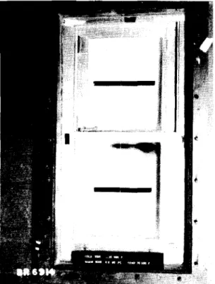
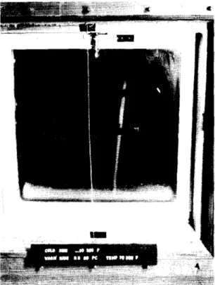
Figures
7
and 8 are photographs which show the extentof condensation on the inside surfaces of the outer panes of
the double double hung and casement windowso It is evident that
a considerable amount of frost had accumulated on the outer panes of the double double-hung window during the course of the
con-densation tests.
On
the other handg there was littleff anyfrost accumulation on the outer pane of the casement window. Measurements of air pressure differences across the
partition (Figo 4) indicated that the casement window was located
at a level where inflow of air from the cold room to the warm room occurred while the double double-hung window was in a region
where outflow of air from the warm to the cold room occurredo
The pressure differences were set up as a result of the differences
in density of the cold room and warm room air. The flow of air
from the warm room to the air space of the double double-hung
window had a ィオュゥセゥョァ effect on the spaceg while the flow of
air from the cold room to the air space of the casement window had a dehumidifying effect on the space.
The direction of air flow in an actual installation will depend on the location of the window with respect to the building
neutral zone (ioeo the level at which inside pressure equals ッオGエセ
12
-TABLE 5
CONDENSATION ON INTERIOR SURFACES OF DOUBLE DOUBLE-HUNG WINDOW
COLD ROOM HUMIDITY IN EXTENT OF CONDENSATION
J
TEMPERATURE WARM ROOM
(OF) dRH Dew pt (OF) Frame Inside Surface
1°
of Inner Panes
_.
20 46 48.5 Moisture on l-h- inoc:
sill
0 30 37.5 Ice on sill 2 in.
0 380 5 44.5 Moisture on sill Bottom half
and extending
!
way up sides-20 20 27.5 Frost on sill
--20 30 37.5 Ice and frost on Bottom half
sill, moisture
extending
!
way13
-TABLE 6
CONDENSATION ON INTERIOR SURFACES OF CASEMENT WINDOW
COLD ROOM
TEMPERATURE WARJ:.'I ROOK EXTElT':r Oiil JOlTJJEITSA'I'ICil"
(OF)
;bI-lli
Dew Pt (OF) Frame Sash Inside Surfaceof Inner Pane
20
46
48.5
none All over ャセM ino0
30
37.5
none Bottom 2 inahalf
0
3805
44.5
none All over Bottom half-20
20
27.5
none Frost on Iino
"2
bottom half
-20
30
37.5
Ice Ice and Bottom halfon frost on
sill bottom of
14
-v
SUMMARY AND CONCLUSION1) The air infiltration rates for the double double-hung
and casement windows were 10 2 and 0,6 cfm per foot of sash crack,
respectivelY1 at a pressure difference eqUivalent to the velocity
head of a 25-mph wind. This can be compared to the maximum
allowable air infiltration rate for these types of windows of 00 5
cfm per foot of sash crack given in the Specificiation of the Aluminum Window Manufacturers Association.
2) There were substantial vertical variations in the
surface temperatures of the frame of the double double hung window
and the sash of the casement window. There were smaller vertical
variations in the surface temperatures of the frame of the casement
window. It is not clear to what extent the frame and sash
tempera-ture variations were due to differences in the amount of inside and outside exposed surface area as compared to lateral heat exchange with surrounding construction, particularly the window air spaceo A more comprehensive study of the relative effects of lateral heat exchange, the ratio of inside and outside exposed areas and the location of the thermal breaks is suggested.
3) As a criterion of the thermal performance for metal frames or sash it is suggested that the inside surface temperature of
the metal should at no point be lower than the minimum surface temperature of the inner pane.
4) The 9Jl6-in. wood spacer as used in the frames of both windows resulted in inside frame surface temperatures equal to
or slightly lower than the corresponding glass surface temperatures0
In terms of the criterion suggested in Noo3 above, 'the "thermal
breaklt provided by the 9/16-in. wood spacer might be regarded as
borderline0 The 1/4-in. hard-board spacer in the sash of the
casement window resulted in inside sash surface temperatures
substantially less than the corresponding glass surface temperatures and might therefore be regarded as inadequate as a "thermal break"o
In view of these results it would appear that many of the "thermal
breaklt arrangements presently being used in'metal windows are
HEAD SILL 8'I,' WEATHERSTRIP I III '" "
.
.," I I VINYL⦅Nセ
t--" ·1 Z'4' I'l' .• • I ·-I.I_----_=---..::!....- ..-{•
ICAL! (llIC... I. HORIZONTAL SECTION o VERTICAL SECTION FIGURE I7/8"
セ セ MセMMMMMMMMMMMMMセセセZMMMMMMMMMMMMMMMセ
IJ/
iI I
I I jMセ
セMM
A.-"-___ '
I-<L-.J ....do- セ!
'0/ - セ セ I :
"'t
!
(.i Il I I I+
セ
I.
• I I I I 1 I ! I I I/
!
1 : I I I I JI-_--LJ- NlMjMMMェセ!
1 N⦅j⦅ャ「セセ[Zj[[[[[ャ[エZZ]]]]]]]]]]]]]]]]]V[ャ[[[[[[[ャ[[[[[[[ャ[[[[[[[j[[[Ql⦅ャMMMj I I I I I I1/----:---,
iセ 22' I , VINYL WEATHERSTRIP I HARDBOARD Ii !I
I i 8' IOY4'FIGURE
2
DETAILS
OF THE
CASEMENT
WINDOW
SECTION A-A 2". 8" FRAMING---<-t
Iii' PLYWOOD
'14' MASONITE----!F-"'l 2 INCH "FIBRE GLAS"
BATT INSULATION.
r-f>
A I ! I IV
...
セ»>
19" '..
.;;: CD..,
; . ' , .'. セ..
I .... Gl .. ..'..: '. : '. .' 23-1/4' "....J::...
...
:::\1
- ,".セZZZ セ .::' .::\:.... 49- 3/4' セaWALL PANEL WITH MASONITE REMOVED
FIGURE 3
AUXILIARY DIFFUSER COLD ROOM MAIN DIFFUSER •
•
I..
lt1
-•
;--POLYTHENE CURTAINWALL PANELS (NOT UNDER TEST)
セセ
WARM ROOM THERMOSTAT foセゥG|A
TEMPERATURE • CONTROLLER セI HUMIDITY SENSING セ ELEMENT OF »-> ELECTRIC HYGROMET E R BASEBOARD CONVECTORS,
FIGURE 4
PLAN OF COLD ROOM
4-DOUBLE DOUBLE HUNG WINDOW CASEMENT WINDOW LEGEND 0-0
.-.
0·2 0-4 0-6o-s
1-0 1-2 1-4 1-6r-a
2-0 AIR INFILTRATION RATE C_F.M_ PER FOOT OF SASH PERIMETERen セ o c 0-300 z セ en en o 0:: o <X 0-200 セ o z セ 0:: セ u, u, 0-100 c セ 0:: セ en en セ 0:: Q. u, o 0-400 z
i
0 - 5 00 __MNNセMMNセ
- -NLNNMセMMMイMMMMイMMMMイMMNNNNNMMNNL
0:: セ t-<X セFIGURE
5
AIR
INFILTRATION
CHARACTERISTICS
FOR THE CASEMENT AND DOUBLE
(COPPER) (CONSTANTAN) I It セ 8" 2·
FIGURE 6A
SURFACE THERMOCOUPLE FOR
.ALUM
INUM
FRAME
(COPPER) (CONSTANTAN) I I---
1-FIGURE 6 B
SURFACE THERMOCOUPLE FOR INNER AND
OUTER PANE
FIGURE 1 FROST ACCUMULATION ON INSIDE SURFACE OF THE OUTER PANE