HAL Id: tel-02918119
https://tel.archives-ouvertes.fr/tel-02918119
Submitted on 20 Aug 2020
HAL is a multi-disciplinary open access
archive for the deposit and dissemination of sci-entific research documents, whether they are pub-lished or not. The documents may come from teaching and research institutions in France or abroad, or from public or private research centers.
L’archive ouverte pluridisciplinaire HAL, est destinée au dépôt et à la diffusion de documents scientifiques de niveau recherche, publiés ou non, émanant des établissements d’enseignement et de recherche français ou étrangers, des laboratoires publics ou privés.
of multiple probes trajectories for pre-operative
planning of percutaneous thermoablation interventions
Amir Jaberzadeh
To cite this version:
Amir Jaberzadeh. Simulation of heat transfer and automatic optimization of multiple probes trajec-tories for pre-operative planning of percutaneous thermoablation interventions. Automatic Control Engineering. Université de Strasbourg, 2015. English. �NNT : 2015STRAD003�. �tel-02918119�
UNIVERSITÉ DE STRASBOURG
Ecole doctoraleTHÈSE DE DOCTORAT
présentée par :Amir Jaberzadeh
soutenue le : 13 Février 2015pour obtenir le grade de :
Docteur de l’université de Strasbourg
Mention: Informatique
Simulation de transfert de chaleur et
l'optimisation automatique des probes
trajectoires multiple de la planification
pré-opératoire pour les interventions
percutanées thermique
THÈSE dirigée par :
Mme. Essert Caroline HDR, Université de Strasbourg
RAPPORTEURS :
M. Warfield Simon Thorne Griscom Chair de Radiology,Ecole de médecine d'Harvard
M. Jannin Pierre Directeur de Recherche, Université de Rennes 1
AUTRES MEMBRES DU JURY :
M. Collet Pierre Professeur, Université de Strasbourg
Acknowledgements
I would like to express my special thanks to Dr. Caroline Essert for her support, encouragement and patience during my PhD pursuit. I would like to thank her for guiding my research and for al-lowing me to grow as a research scientist. Her advice and experience during my research as well as on my career have been priceless.
Besides my advisor, I would like to thank my jury members Dr. Simon Warfield and Dr. Pierre Jannin for their precious time reading my thesis. I should also appreciate other members of the jury Prof. Pierre Collet and Prof. Afshin Gangi for their time and constructive comments on my defense. This research work could not be performed without validation of patient data. Hence, I would like to thank Dr. Elena Kaye and all other people collaborating with this research in Memorial Sloan Kettering Cancer Center for the data collection and other medical consultations.
I would like to extend my appreciation to my friends in Computer Graphics and Geometry labor-atory (IGG) who motivated me during tough times. Finally, I would like to thank my family who has always been supporting me throughout my life with their faith and love.
Abstract
Context
Today, several minimally invasive techniques allow surgeons to perform tumor ablation proce-dures without opening the patient. Cryosurgery (also called cryoablation or cryotherapy) is one of these techniques. It has been introduced to treat prostate cancers in the early 1960s and works by decompressing very rapidly a gas (usually argon) through a needle-like probe. As the argon flows through the needle, a ball of ice crystals forms around the tip of the probe, thus immediately leading to cellular death of the surrounding tissues. Depending on the tumor location and size, multiple cry-oprobes with different types can be employed.
For the surgeons, estimating pre-operatively the final results and planning the surgery in advance in a complicated anatomical environment is very challenging. Over- or under-ablation may result in complications during the treatment. Therefore, an ablation planning system plays an important role in tumor ablation procedures, as it provides a dry run to guide the surgeons. In most planning appli-cations, the ablation zones are typically described as simplified non-realistic ellipsoids around the cryoprobes tips and due to the presence of cooling blood vessels in the vicinity of the needles the necrosis volume size may be over-estimated and the tumor incompletely ablated. To overcome the-se issues, numerical simulations bathe-sed on bioheat equation are propothe-sed to allow for an accurate estimation of the ablation zone to incorporate heat-sink effects of large blood vessels.
Another big challenge is the feasibility of multiple needles placement satisfying some constraints like avoiding anatomical and vital organs, or the translation of some technical surgery rules like minimal trajectory length, tangency to organs while penetrating their surface and marginal tumor ablation volume. Given the lack of a planning tool addressing all these conditions and the crucial need for such a planner, in this thesis we focused on software-assisted cryosurgery planning aiming at supporting the physician by utilizing a more realistic prediction of the ablation zones, and propos-ing a needle placement setup with a risk close to minimum for the patient and an optimal coverage of the tumor by the iceball in an acceptable time for a use in the operation room.
Simulation
Among different proposed methods for the interpretation of thermal propagation in living tissues, one of the most widely used methods called Modified Penne’s bio-heat transfer equation was select-ed. In order to keep the genericity of our planning tool for combined cryosurgery and hyperthermia, the effective heat capacity method was used to numerically solve the phase change problem with multiple moving boundaries.
which can be applied to frozen, partially frozen and unfrozen tissue regions, was created. In this equation, the tissues were treated for freezing or thawing with multiple needles over a temperature range, and the influence of blood perfusion and metabolic heat generation has been taken into ac-count for the unfrozen and undamaged region. For the discretization purposes we have used an ex-plicit backward differentiation method.
We used several visualization methods including 2D slices, 3D meshes and volume rendering to overlay the ablation zone onto the anatomical images. In order to estimate the accuracy of our ap-proximation method, the computed ablation zone was overlaid on its corresponding segmented re-gion of intra-operative images for cases of one and two needles. To show the heat sink effect of large vessels on the deformation of iceballs we compared the ablation zone with simplified ellipsoid iceballs proposed by the manufacturers in complex vascular situations, extracted from experimental data sets. Hausdorff distance, Dice coefficient and Boolean volume overlap were used for compari-son purposes.
Our contribution for this part includes considering an estimation of large vessels heat sink effect in computation of ablation zone which has not previously been taken into account in cryosurgery planning. An interactive framework was developed to manually change several needles positions and orientations and visualize their computed ablation zone for surgical assistance or training pur-poses. Finally, since it is one of the long-term goals of our planning tool, the simulation of heat propagation was designed to be solved for different surgical thermo-ablation routines.
Multiple trajectory planning
The multi-objective nature of tumor ablation planning problem can be can be classified under Non-deterministic Polynomial (NP) problems in terms of computation. A simplified problem of optimizing full tumor coverage was translated into a problem of minimal coverage by several ellip-soids or simulated bioheat isotherms of multiple needles.
A number of constraints were applied to this problem. These constraints could be represented as solution space avoiding vital structures or tangency to the liver capsule. They were satisfied in a preprocessing step creating an approximately safe insertion zone over the skin. Other constraints such as needles crossing avoidance and full tumor coverage could be computed at each iteration of optimization process. These constraints are highly non-linear and therefore were resolved by devel-oping appropriate optimization methods and penalty functions.
Next, several objective functions were introduced in our planning tool in order to minimize the volume of damaged healthy tissue, and maximize the distance of multiple needle trajectories to ves-sels and vital organs. For scalarization of this multiple objective function, a weighted sum criterion was applied and each objective function was normalized beforehand to a value between 0 and 1.
Different optimization methods suitable for this type of problem were experimented, from de-terministic to stochastic and derivative free to model based. Speed, accuracy and robustness of some of these methods were compared in a search domain with different complexities. Other characteris-tics of methods like sensitivity to initial parameters were also analyzed. For validation purposes a comparison was done with a synthetic ground truth, and the results were compared with the results
obtained using a Monte-Carlo sampling method. Moreover they were compared with intra-operative images of a patient for the case of two needles.
Our contribution in this part includes the development of an automatic planning tool for cryosur-gery, optimizing multiple needles with full degree of freedom for needle placements while avoiding obstructive and vital organs, a generic tool which accepts new surgical and anatomical constraints based on the organ being operated, integrating simulation and planning steps for tackling a real cry-osurgery planning problem and two phase optimization approach to combine simplified ellipsoids and bioheat simulation for obtaining fast planning results.
Conclusion and future works
In this PhD thesis, a planning tool for multiple needle cryosurgery was developed integrating the bioheat simulations for defect region computation in the optimization process. Non-linear con-straints were resolved using a one-time preprocessing step and introducing several penalty func-tions. A two-phase optimization process was used which shows more accurate result in acceptable computational time applicable in the operation room. The effect of vessels on deformation of ice-balls demonstrated the important role of vessels in iceball formation and tumor recurrence if under-estimated.
Using parallel processing algorithms could be proposed in the future for faster and finer compu-tation of bioheat equation while keeping numerical solution more stable to the input parameters. Introducing deformable needles to our planning tool would also increase the range of applicability and produce more realistic results.
Keywords
Résumé
Contexte
Différentes techniques de chirurgie mini-invasive permettent aujourd’hui d’effectuer les procé-dures d'ablation de tumeurs. La cryochirurgie (également appelée cryoablation ou cryothérapie) est une de ces techniques. Elle a été mise en place au début des années 1960 pour traiter les cancers de la prostate. Elle fonctionne grâce à une technique de décompression très rapide du gaz (générale-ment de l'argon) à l’extrémité d’une sonde en forme d'aiguille. Lorsque l'argon s’écoule à travers l'aiguille, une boule de cristaux de glace se forme autour du bout de la sonde, ce qui conduit immé-diatement à la mort cellulaire des tissus environnants. Selon l'emplacement de la tumeur et la taille de la tumeur, plusieurs aiguilles, éventuellement de types différents, peuvent être utilisées simulta-nément afin de couvrir la totalité de la tumeur.
La planification préopératoire de ce type d’intervention est très difficile pour le chirurgien, qui doit se représenter mentalement la disposition finale des aiguilles par rapport à la position des struc-tures anatomiques environnantes, ainsi que la forme finale du glaçon formé autour des pointes des aiguilles, afin de choisir une stratégie de placement dans un environnement anatomique complexe. Une sur-ablation ou une sous-ablation peuvent entraîner des complications au cours du traitement. De même, un mauvais placement peut également entraîner des complications, notamment des hé-morragies. Ainsi, le système de planification d'ablation joue un rôle important dans les procédures d'ablation de la tumeur car il fournit une simulation virtuelle pour guider les chirurgiens.
Dans la plupart des applications de planification existantes les zones d'ablation sont typiquement décrites comme des ellipsoïdes simples non réalistes autour des aiguilles. Pourtant, en raison de la présence de vaisseaux sanguins dans le voisinage des aiguilles pouvant provoquer un effet de ré-chauffement, le volume de nécrose peut être déformé, sa taille peut être diminuée, et la tumeur peut n’être que partiellement soumise à une ablation. Pour remédier à ces problèmes, des simulations numériques basées sur l'équation de transfert de chaleur ont été utilisées pour permettre une estima-tion précise de la zone d'ablaestima-tion intégrant les effets de dissipaestima-tion de chaleur des gros vaisseaux sanguins.
Un autre grand défi est l’automatisation du choix de placement tridimensionnel de plusieurs ai-guilles simultanément, qui adoptent les contraintes habituelles sur des aiai-guilles individuelles (par exemple des règles de sécurité comme l’évitement des organes vitaux et les éléments anatomiques, des règles techniques comme la longueur maximale d’aiguille limitant la longueur de la trajectoire, ou encore des règles relatives à la cautérisation), ainsi que des contraintes supplémentaires liées à l’interaction entre les différentes aiguilles (non intersection, interaction des effets).
crucial d'une telle planification, dans cette thèse nous nous sommes concentrés sur la planification préopératoire automatisée de la cryochirurgie, avec deux objectifs principaux : 1) assister le chirur-gien grâce à une prédiction plus réaliste des zones d'ablation et 2) proposer automatiquement un placement d'aiguille avec un risque minimal pour le patient et une couverture optimale de la tumeur par la boule de glace, dans un délai acceptable pour une utilisation en salle d'opération.
Simulation
Afin de modéliser la propagation thermique dans les tissus vivants, l'une des méthodes les plus couramment utilisées, l'équation de transfert de chaleur de Pennes, a été choisie. Afin de garder la généricité de notre outil de planification pour la cryochirurgie combinée et l'hyperthermie, la mé-thode efficace de la capacité thermique est utilisée pour résoudre numériquement le problème de changement de phase avec des frontières mobiles multiples. Sur la base de cette solution qui satis-fait automatiquement les conditions de changement de phase, une équation unifiée, qui peut être appliquée aux régions de tissus gelées, partiellement gelées et non-gelées est crée. Dans cette équa-tion les tissus sont traités pour le gel ou le dégel avec plusieurs aiguilles sur une gamme de tempéra-ture, et les influences de la perfusion sanguine et de la production de chaleur métabolique ont été prises en compte pour la région non-gelée. Pour la discrétisation nous avons utilisé une méthode de différenciation arrière explicite.
Nous avons utilisé plusieurs méthodes de visualisation, y compris les tranches 2D, les mailles 3D et le rendu volumique pour superposer la zone d'ablation sur les images anatomiques. Afin de vali-der la méthode d'approximation, la zone d'ablation calculée a été superposée sur sa région segmen-tée correspondante sur des images post-opératoires, dans des cas d’ablation à une et deux aiguilles. Afin de montrer l'effet de dissipation de chaleur des vaisseaux sur la déformation des boules de glace, nous avons comparé la zone d'ablation avec les boules de glace ellipsoïdales simplifiées indi-quées par les fabricants, dans les situations vasculaires complexes extraites de 10 ensembles de données réelles. Distance de Hausdorff, coefficient de Dice et chevauchement de volume booléen ont été utilisés pour la comparaison.
Notre contribution pour cette partie comprend l’étude de l’effet dissipateur de chaleur des gros vaisseaux dans le calcul de la zone d'ablation qui n'a encore jamais été pris en compte dans un con-texte de planification de cryochirurgie dans la littérature. Un cadre interactif a été conçu pour modi-fier manuellement les positions et les orientations de plusieurs aiguilles et pour visualiser la zone d'ablation calculée, à des fins d'assistance ou de formation chirurgicale. Enfin, de façon à prendre en compte la simulation de différents types de thermo-ablation et de conserver l’aspect générique de l’outil de planification, nous avons utilisé des approches gérant aussi bien les ablations par hypo- (cryoablation) que par hyperthermie (radiofréquence).
Planification de trajectoire multiple
Le problème de planification automatique d'ablation de tumeur est un problème multi-objectif, qui consiste à trouver le meilleur compromis satisfaisant au mieux les multiples contraintes qui s’appliquent. C’est un problème compliqué, dans lequel la nature multi-objectif du problème est
difficile à résoudre, mais également chaque contrainte séparément peut être complexe. En particu-lier, le recouvrement de la totalité de la tumeur par un volume de glace minimal est mathématique-ment proche de problèmes classiques de couverture minimale d’un objet avec plusieurs autres formes géométriques, ici des ellipsoïdes (version simplifiée) ou des surfaces isothermes simulées par l’équation de transfert de chaleur depuis les aiguilles. Ce problème de recouvrement peut être classé dans les problèmes polynomiaux non-déterministes en termes de calcul.
Un certain nombre de contraintes a été appliqué à ce problème. Ces contraintes représentent : 1) la création d’une zone délimitant les points d’insertion possible, permettant par exemple d’éviter différents organes tels que les os et la moelle épinière, les gros vaisseaux, ou permettant de ne pas entrer de façon trop tangente par rapport à la surface du foie : ces contraintes sont satisfaites dans une étape de pré-traitement créant une “zone d’insertion”, projection sur la peau des trajectoires faisables; 2) la minimisation de valeurs numériques représentant par exemple des règles de non intersection des aiguilles, ou la couverture complète de la tumeur : ces valeurs doivent être calculées à chaque itération d’un processus d'optimisation. Ces contraintes sont fortement non-linéaires, et ont donc été résolues par le développement de fonctions de pénalité appropriées.
Plusieurs fonctions objectif ont été introduites dans notre outil de planification afin de minimiser le volume de nécrose des tissus sains et de maximiser la distance des trajectoires multiples des ai-guilles aux vaisseaux et aux organes vitaux. Pour transformer cette fonction multi-objectif en une unique fonction mono-objectif à minimiser, une somme pondérée est utilisée et chaque fonction objectif est normalisée à l'avance.
Différentes méthodes d'optimisation adaptées à ce type de problème ont été utilisées : détermi-nistes ou stochastiques, basées gradient ou sans dérivée, heuristiques ou basées modèle. La vitesse, la précision et la robustesse de certains de ces procédés ont été comparées dans un domaine de re-cherche avec les différentes complexités. D'autres caractéristiques de ces méthodes, telles que la sensibilité et les paramètres d'entrée, ont également été analysées. À des fins de validation, des ex-périmentations ont été menées en définissant une configuration a priori de la zone d'ablation et les résultats ont été comparés avec les résultats obtenus en utilisant une méthode de recherche exhaus-tive. En outre, ils sont comparés aux images post-opératoires des patients pour le cas d'un et de deux aiguilles.
Notre contribution dans cette partie comprend l'élaboration d'un outil de planification automa-tique pour la cryochirurgie, pour l'optimisation 3D de plusieurs aiguilles à tous degrés de liberté tout en évitant les organes obstructifs et vitaux, un outil générique qui accepte des nouvelles con-traintes chirurgicales et anatomiques basées sur l'organe opéré, en tenant compte de l’intégration des mesures de simulation et de planification, et un approche d'optimisation en deux phases pour combiner ellipsoïdes simplifiés et la simulation de transfert de chaleur afin d’obtenir les résultats rapides.
Conclusion et perspectives
Dans cette thèse, un outil de planification pour la cryochirurgie avec aiguilles multiples a été élaboré en tenant compte de l’intégration de simulations de transfert de chaleur dans le processus d'optimisation. Les contraintes non-linéaires ont été résolues en utilisant une étape unique de
pré-traitement et en introduisant plusieurs fonctions de pénalité. Un processus d'optimisation en deux phases a été utilisé, qui permet d’obtenir un résultat plus précis en un temps de calcul acceptable et applicable en salle d'opération. L’étude de l’influence des vaisseaux a démontré le rôle important des vaisseaux dans formation de la boule de glace, souvent surestimée par les méthodes habituelles, et donc dans les risques de récidive de la tumeur.
Dans de futur travaux, l’utilisation d’algorithmes de traitement parallèle pourra être proposée pour le calcul rapide et plus fin de l'équation de transfert de chaleur, en gardant la solution numé-rique plus stable pour les paramètres d'entrée. L’introduction de modèles d’aiguilles déformables dans notre outil de planification pourrait également augmenter l’éventail d'applications et produire des résultats plus réalistes.
Mots-clés
Planification chirurgicale automatique, simulation de chaleur de Pennes, optimisation sans déri-vée, cryochirurgie
Contents
Acknowledgements ... v Abstract ... vi Keywords ... viii Résumé ... ix Mots-clés ... xiiList of Figures ... xvi
List of Tables ... 20
Chapter 1. Introduction ... 21
1.1 Overview ... 21
1.2 Medical background ... 21
1.3 Minimally invasive surgery ... 22
1.3.1 Cryosurgery ... 23
1.3.2 Radiofrequency ablation (RFA) ... 26
1.3.3 Deep brain stimulation ... 27
1.4 Challenges and research contributions ... 28
1.5 Thesis outline ... 30
Chapter 2. Related works ... 33
2.1 Overview ... 33
2.2 Cryosurgery simulation ... 33
2.3 Surgical planning ... 34
2.3.1 Cryosurgery ... 35
2.3.2 Other types of hyperthermia ... 38
2.3.3 Deep brain stimulation DBS... 43
2.4 Problem statement ... 45
Chapter 3. Data preparation and preprocessing ... 47
3.1 Overview ... 47
3.2 Data preparation ... 47
3.2.1 Retrospective dataset ... 47
3.2.2 Test dataset ... 50
Chapter 4. Simulation of cryosurgery ... 53
4.1 Overview ... 53
4.2 Numerical method of the heat propagation ... 53
4.3 Numerical values and discretization parameters ... 55
4.4 Results ... 58
4.5 Validation ... 62
4.6 Conclusion and discussion ... 68
Chapter 5. Geometric constraints ... 69
5.1 Overview ... 69
5.2 Constraints structure ... 69
5.3 Required algorithms ... 72
5.3.1 Volume optimization ... 72
5.3.2 Crossing needles condition ... 76
5.3.3 Insertion zone ... 77
5.4 Conclusion ... 78
Chapter 6. Planning and optimization ... 79
6.1 Overview ... 79
6.2 Introduction ... 79
6.2.1 Optimization problem ... 79
6.2.2 Constraint handling ... 81
6.3 Surgical planning formulation ... 82
6.3.1 Problem formulation ... 82
6.3.2 Optimization methods ... 84
6.4 Experimental study ... 87
6.4.1 Tumor coverage problem ... 88
6.4.2 Planning in presence of all constraints ... 92
6.4.3 Influence of the initial point on optimization ... 95
6.4.4 Influence of the insertion zone on the optimization ... 97
6.4.5 Hybrid opimization and multiple output ... 98
6.4.6 Two-phase optimization ... 100 6.5 Validation ... 103 6.5.1 Ground truth ... 103 6.5.2 Monte-Carlo optimization ... 104 6.5.3 Surgeon planning ... 104 6.6 Conclusion ... 105
Chapter 7. Conclusion and discussion... 107
7.1 Overview ... 107
7.2 Conclusion and discussion ... 107
List of Figures
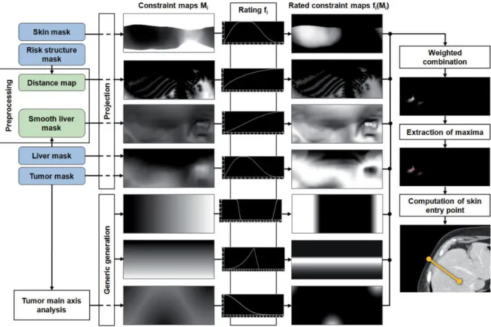
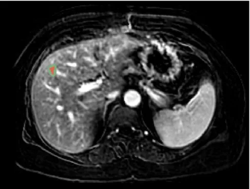
Figure 1-1 The left image shows the liver located in the human's body and the right image shows the blood flow in the liver [1] ... 21 Figure 1-2: Axial view of the liver CT slice containing a tumor as a darker region indicated by red circle 22 Figure 1-3: Needle tip inner structure (GalilMedical Co.) ... 23 Figure 1-4: Different types of needles with their respective iceball shape (GalilMedical Co.) ... 24 Figure 1-5 Avoiding risky regions is shown for cryosurgery planning. Ribs, vessels and spine are avoided taken from [10] ... 25 Figure 1-6 (a) Schematic illustration of the tangency constraint, which ensures that the angle in which the trajectory intersects the liver surface is bigger than 20° (b) The needle length constraint excludes all insertion trajectories from the insertion zone that are longer than the needle length [9] ... 26 Figure 1-7 Approximated deformation of ablation region in RFA [13] ... 26 Figure 1-8 Bipolar RFA needle in the vicinity of blood vessels. Temperature isosurfaces are shown [14] 27 Figure 1-9 Cross section of probe placement for the DBS [19] ... 28 Figure 1-10: Flowchart of the proposed workflow. It supports four different surgical-assistive pipelines chosen by the surgeon based on his requirements ... 30 Figure 2-1 Hausdorff distance computed between the segmented and simulation based iso-surfaces a) one needle b) two needles [33] ... 34 Figure 2-2 The virtual cryo-probes shown in red which simulate the needles and the frozen tissue, can be set into the patient’s segmented anatomy. The tumor and its additional 0.5cm safety margin, is shown in brown. The large vessels are in blue, the gallbladder in green and the bones in white. a) and b) show the radiologists setup chosen for this specific case, while they can have a better setup which would have decreased significantly the danger of undertreating the cancer in images c) and d) [15]... 36 Figure 2-3 2D bubble-packing results and the corresponding simulated temperature field for three cases [42] ... 37 Figure 2-4 Schematic illustration of cryosurgery planning: (a) the prostate and urethral warmer are modeled based on ultrasound images, (b) bubble packing generates a recommended cryoprobe layout [41] .... 37 Figure 2-5 Case of 12 cryoprobes (a) Initial position of configurations (where each small circle represents a cryoprobe, cryoprobes of different colours belong to different configurations, and the tumor is represented by the large black circle). (b) Final position of the configurations collapsed into one after ACO. (c) Temperature distribution for the optimal solution (i.e. the one characterized by the minimum value of the cost function): 0°C isotherm contour is red, -22°C isotherm contour is light green, and -45°C isotherm contour is blue. (d) Plot of the defected pixels (white) [44] ... 38 Figure 2-6 Synchronous 2D and 3D views enable the user to quickly check if either bony structures or important vessels lie on an applicator’s path [46] ... 39 Figure 2-7 Ablation zone models are deformed in real-time by moving their vertices according to the proximity of large surrounding liver vessels [47] ... 39 Figure 2-8 Color map is overlaid on a pre-computed insertion zone using a weighted sum of soft constraints. Red represents high risk regions while green shows the safe ones. ... 40 Figure 2-9 Outline of the algorithm: Input masks (blue) are used to generate constraints maps and preprocessing results (green) (in vertical order: penetration depth, distances to risk structures, liver capsule penetration angle, portion of healthy liver tissue, circumference, angulation, tumor coverage). They are rated and combined into one image from which maxima are computed [53]. ... 41
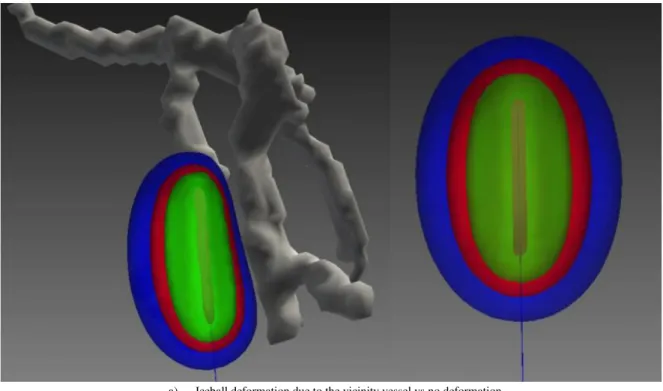
Figure 2-10 Trajectory planning workflow and resulting surfaces. For the hard constraints, the insertion zone is shown transparently green. The result of the soft constraints is visualized with a color gradient ranging from red (poor rating) to green (good rating) [9] ... 42 Figure 2-11 Both probes of an internally cooled bipolar RF applicator are sampled. The corresponding weighted distance field is illustrated by isoline contours. The thermal fields of the blood vessels and the cooled applicator shaft decrease the ablation zone (blue regions) [13] ... 43 Figure 2-12 In (a), The vessel A presence leads to a deformation of the ablation zone in accordance with the heat-sink effect. A similar situation is illustrated in (b). If an independent cooling effect is assumed, the final ablation zone is achieved by the intersection of both ablation zones (c). In contrast, if both vessels jointly cool the heat field, the heat-sink appears more smoothly (cf. blue peak), similar to the results of numerical simulations (d) [13] ... 43 Figure 2-13 An example of ablation spheres and trajectories; blue spheres indicate the ablation spheres and green lines indicate possible needle trajectories [57] ... 44 Figure 2-14 An automatic planning tool for DBS presenting approved trajectory to the neurosurgeon [58] 44 Figure 2-15 Color maps of the soft constraints obtained after phase 2 of the solving process: best zones are in green and worst are in red. The best trajectory is shown as a red line [59] ... 46 Figure 3-1: Ribs in yellow and skin in white registered on MRI image of the patient. A segmented part of the liver also can be seen in red. ... 48 Figure 3-2: Intra-operative images are aligned to T1. Red contour shows liver from T1 high-resolution images, green represents tumor location while background image demonstrates intra-operative image49 Figure 3-3: Tumor dilation to create the safe margin. Green patch represents 2mm dilated version of the tumor in red ... 50 Figure 3-4: Left: 2D segmented organs; Right: surface meshes of the segmented organs ... 50 Figure 3-5 Constraint concept of the automatic trajectory planning. Surfaces of the skin, the liver, the tumor and other critical structures are created from corresponding segmentations. The insertion zone on the skin is determined after applying a combination of hard constraints ... 52 Figure 4-1 bioheat moving boundary and three different temperature fields generated [28] ... 54 Figure 4-2 Schematic of 3D geometry for one probe case [30] ... 56 Figure 4-3 quantification error shown for the needle tip on the top and for the tumor mesh reconstruction on the bottom ... 57 Figure 4-4 Simulated 0 °C iceball in blue is compared to its corresponding iso-therm in yellow reported by the manufacturer ... 59 Figure 4-5 Synergic effect of two needles on the simulated iceball comparing to separate ellipsoids . 60 Figure 4-6 iceball deformation due to the vicinity vessels ... 61 Figure 4-7 Sequential axial slices of iceballs encountering vessels. Simplified ellipsoid refers is shown in yellow and 0, -20 and -40 °C iceballs from blue to green. Vessels are in pink. ... 62 Figure 4-8 In this image segmented iceball-2 is shown in white besides segmented cryoprobes in light yellow. The simulation cryoprobes are shown as red trajectories within segmented cryoprobes. ... 63 Figure 4-9 Simulated iceball in blue versus segmented iceball-1 in white for a 10 minute freezing cycle. Theoretical ellipsoid is shown in yellow. Vessels are in pink. ... 63 Figure 4-10 Hausdorff distance computed for each vertex of the segmented iceball-1 mesh. Blue color indicates a low distance while large distances are in red ... 64 Figure 4-11 Simulated iceball in blue versus segmented iceball-2 in white for a 10 minute freezing cycle. Theoretical ellipsoids are shown in yellow and vessels in pink. ... 64 Figure 4-12 Hausdorff distance for total vertices is improved by the simulation. This is visible due to statistical parameters of the boxplot ... 65
Figure 4-13 Hausdorff distance computed for each vertex of the segmented iceball-2 mesh. Blue represents low distances while red is used for large distances ... 66 Figure 4-14 Hausdorff distance improvement for total vertices in iceball-2 is less visible and only the average of boxplot is reduced. ... 66 Figure 4-15 Boolean operations for comparing ellipsoid in left and simulation in right. For both of them the segmented iceball was used as reference mesh. First row is computed for intersection, second row is difference and last row is the union of each mesh with the reference mesh. ... 67 Figure 5-1 Tree representation of the constraint risk_vessels expressing the maximization of distance to vessels: operators are in red, given constant data are in orange, and the variable is in blue. ... 71 Figure 5-2 Check tumor coverage a) vertices extracted from the tumor mesh are used for the test while in b) tumor is voxelized and the inclusion of each voxel is verified [16] ... 74 Figure 5-3 Two proposed methods for computing the volume of the ablated healthy tissue while using multiple ellipsoids. ... 76 Figure 5-4 Computing uncovered tumor volume and ablated healthy volume while dealing with iceball isotherm surface. ... 77 Figure 6-1 One needle ellipsoid can’t cover the tumor with a smaller volume due to the non-homogeneity of tumor shape ... 88 Figure 6-2 Profile of the objective function values while covering the tumor with two different needle numbers. Speed and accuracy of the methods are compared using this profile. ... 89 Figure 6-3 Comparing the profile of optimizer’s objective function value in the tumor coverage problem for two cases ... 91 Figure 6-4 Profile of the optimizer’s objective function value in presence of all constraints. Similar needle numbers and optimization methods are used in contrast to the cases with only tumor coverage constraint, but they are named and sketched differently for comparison purposes. ... 93 Figure 6-5 Effect of needle size on the solution of the hard problem. Profile of the objective functions shows that in a complex problem with all constraints and large tumor increasing the ablation zone can lead to a solution. ... 94 Figure 6-6 Changing the soft weights in the objective function results in crossing the obstacles while trajectories in both cases are inside the insertion zone. ... 95 Figure 6-7 The effect of insertion zone complexity on the behavior of different optimizers is investigated. In this image solid lines demonstrate the trends of optimizer’s objective function for simpler case#5 while dashed lines refer to the case #6 ... 96 Figure 6-8 The profile of optimizers with two different starting points. Dashed lines illustrate the objective function profiles when using the worst starting point and they are labeled with Optimizer_name2 in contrast to solid lines which were initialized in the middle of their variable bounds. ... 96 Figure 6-9 Computed insertion zone for two cases. Insertion zone in (a) shows a more complex and discontinuous solution space comparing to (b) ... 97 Figure 6-10 Complete trend of the hybrid optimization method is illustrated in the upper image. Eight distinct solutions selected from the first global method is shown along with their following local optimization trends. In the lower image six succesful solutions are compared. ... 99 Figure 6-11 Comparison of single-phase optimization using simulated ablation zone in dashed line and several two-phase optimization methods sketched as solid lines. ... 101 Figure 6-12 Result of planning for case#4 with a simple vascular structure close to the tumor. Ellipsoids are in yellow while simulated iceball is in semi-transparent blue. ... 102 Figure 6-13 Comparison of one phase and two phase planning with a complex vascular structure close to the tumor ... 102 Figure 6-14 Result of planning for case#3 with a complex vascular structure close to the tumor. Iceball is in blue, tumor in gray, vessels in pink and ellipsoids in yellow. ... 103
Figure 6-15 Synthetic tumor is specifically defined in order to validate the convergence of Pattern-search method ... 103 Figure 6-16 The comparison between the 0 °C iceballs in the planning tool in blue and the intra-operative images in white. Tumor in gray is completely covered by -40 °C iceball which is presented as a green surface. ... 104
List of Tables
Table 1 Typical thermophysical properties of soft biological tissues [30] ... 58
Table 2 Similarity coefficient for cases 1 and 2 for ellipsoids and simulated iceballs due to the segmented iceballs ... 66
Table 3 XML formulation of the rule risk_vessel ... 71
Table 4 XML formulation of the volume constraint ... 72
Table 5 Classification of selected methods based on their properties ... 84
Table 6 Specification of input parameters used for the coliny_ea method ... 86
Table 7 Specification of input parameters used in SBO_trust method ... 87
Table 8 Specification of properties for different cases used in the tests ... 88
Table 9 Comparison of four most successful methods after convergence based on the optimizer’s objective function value ... 90
Table 10 Minimum number of iterations for the tumor coverage problem is increased in cases with higher complexity ... 90
Table 11 Comparison of speed and convergence for successful search methods with and without the constraints ... 92
Table 12 The effect of initial point variation on the optimizer’s final objective function value ... 97
Table 13 Final objective function values for five optimizers found in two different conditions of the insertion zone... 98
Table 14 Optimal value of the objective function improved while using the hybrid method ... 98
Table 15 Angular and translational distances of 8 distinct solutions computed after the global optimization. All distances are normalized for each needle and each direction ... 99
Table 16 Average time required for the computation of interpolations in each iteration of local surrogate modeling depending on the number of variables ... 109
Chapter 1. Introduction
1.1
Overview
Cancer is one of the leading causes of death in most of the countries in the world. Among the predominant cancer types, liver cancer ranks fourth due to a high prevalence of hepatitis B. About 500.000 new cases are diagnosed every year in the world. In order to treat liver cancer several kinds of surgical interventions have emerged while treatments based on minimally invasive interventions showed to have long term benefits and fast recovery time. This chapter is organized as follows: for readers with no medical background Section 1.2 introduces the used terminology, the liver’s anato-my and liver treatment options. Section 1.3 covers some minimally invasive interventions related to this thesis. Section 1.4 presents the objectives, challenges and contributions described in this manu-script and a short outline of this thesis will complete this chapter.
1.2
Medical background
The liver plays a major role in metabolism. It is responsible for detoxification, glycogen storage and plasma protein synthesis. It also produces bile, which is important for digestive functions.
The liver has two lobes and is supplied by two major blood vessels: the hepatic artery and the portal vein. The blood leaves the liver by using the hepatic vein. The blood from the artery carries oxygen while the portal vein carries nutrients from the intestine (see Figure 1-1).
Figure 1-1 The left image shows the liver located in the human's body and the right image shows the blood flow in the liver [1]
The liver is an essential organ with a complex vascular anatomy. Probably because of its filtering functions, this organ is one of the most frequently affected by metastases.
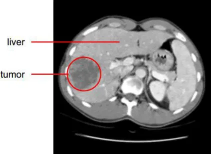
In order to diagnose a liver tumor, imaging technologies for observing the patient’s body struc-ture are required like CT and MRI (see Figure 1-2). Contrast agents are used to highlight structures
such as blood vessels that otherwise would be difficult to delineate from their surroundings. A vio-let fluid such as iodineis is often injected intravenously for highlighting the portal vein.
In order to treat such tumors, surgical interventions like surgical resection (tumor removal) and liver transplantation were used traditionally depending on the size and position of the tumor.
Recently, the emergence of minimally invasive surgeries has enabled treatments aiming at destroy-ing the tumor without opendestroy-ing the patient’s tissue, with equally long-term benefits. Several mini-mally invasive techniques exist, such as microwaves, laser, High-Intensity Focused Ultrasound (HIFU), or percutaneous hyperthermia. In this manuscript we will focus more particularly on the latter, which is now the most frequently chosen by surgeons. It consists in destroying the tumor by extreme heat or cold, using methods such as radiofrequency ablation or cryotherapy.
1.3
Minimally invasive surgery
Minimally invasive surgery has gained an increasing interest in the past decades. By keeping benefits similar to conventional surgery, minimally invasive surgery decreases patient’s discomfort and the recovery time due to the small size of incisions. Using pre-operative imaging, computer-assisted ablation planning strategies are elaborated to optimize operation plans. Toolkits currently used by surgeons for visualization of anatomical structures and navigation of real-time images in-clude IGSTK [2] and 3D Slicer [3]. These softwares enable surgeons to visualize the three-dimensional structure of the tumor as well as to envision ablations and to assess the treatment by developing optimal treatment plans intra-operatively. Below we will briefly introduce three mini-mally invasive techniques used in our Trajectory Planning project. We will mainly focus on cryo-surgery of liver tumors as it is the main topic of this thesis.
1.3.1
Cryosurgery
History of cryosurgery (also called cryoablation or cryotherapy) as a clinical method to treat prostate cancers dates back to the early 1960s. Cryoprobes are small needle-like devices with a di-ameter of around 1.5mm (see Figure 1-3). A decompression chamber is located at their tip and they
are inserted into the tumor during laparoscopic surgery or percutaneously under image guidance. A gas is rapidly decompressed resulting in tissue injury based on the Thompson-Joule principle. Two basic mechanisms are believed to cause cryoablation: firstly the direct injury to the cells caused by the freeze-thaw cycle, and secondly the damage caused by freezing the blood vessels of the tumor that can cause an indirect injury to the cells [4].
As tissue freezes, ice crystals will form in the extracellular spaces. This creates a hyperosmotic environment by water withdrawal from the tissue, which causes the cells to loose water by diffu-sion. If the cooling process is sufficiently rapid, the cell will not lose water fast enough to maintain osmotic equilibrium between the cytoplasm and the extracellular space, and the cytoplasm will be-come extremely cooled. A supercooled cytoplasm leads to a lethal injury to the cell [5-8]
Clinical parameters that contribute to the result of cryotherapy include the cooling rate, tissue temperature, duration of freeze-thaw cycles, and the time between the cycles. This technique has been applied successfully to treat several kinds of tumors, including breast cancer, primary or meta-static liver neoplasms, renal, lung, pancreas, and prostate cancer.
In percutaneous cryoablation, the cancerous tissue is frozen using one or multiple needles. Dur-ing this procedure, tissue temperature drops to -40°C around needle tip, which is lethal for the cells inside the iceball volume. The final goal of cryotherapy is the necrosis of cancerous cells while pre-serving surrounding healthy tissue and avoiding damages to vital anatomical structures. For this purpose, an accurate surgical planning needs to be done by surgeons before the operation.
Since only a limited set of active lengths and diameters are available for the manufactured cry-oprobes (see Figure 1-4), and a fixed freezing protocol is usually used, other cryosurgical parame-ters that affect the shape of the iceball such as the number of cryoprobes and the cryoprobe place-ment are good candidates for optimization and planning. Usual planning is done on slice-based reformations of the 3D volume. In these conditions, determining optimal and safe penetration an-gles of the instruments as well as imagining the size and shape of the resulting iceball are very diffi-cult, especially when several cryoprobes are necessary and produce a combined effect. This is
typi-cally done in a trial-and-error task to find the best configuration.
Finding an optimal and safe trajectory consists in: 1) solving mentally many surgical rules rela-tive to the placement of one or several cryoprobes, these rules being sometimes contradictory, and 2) estimate mentally the shape and size of the produced iceball.
Thanks to the abundant literature about cryosurgery planning and intervention procedure, we can establish a summary of the main rules used by the surgeons when selecting an optimal path. A complete set of the chosen rules in this thesis is listed below in which some of them are similar to other related works in the field like the work of Sietel et al. [9]
1. Placement in the target. The tip of the needle must be located in the tumor.
2. Position of the insertion point. The patient can not be on the side, and rarely on the stomach due to anesthesia equipment. We provide our solver with an initial insertion zone corresponding to the nearest point on the side skin.
3. Maximal path length. This rule concerns the maximal length of the path, which obviously has to be shorter than the size of the cryoprobe (see Figure 1-6 (b)) .
4. Risky structures avoidance. It is necessary to find a needle placement that avoids crossing vital, risky, or impassable structures. For liver cryosurgery, the identified “obstacle” structures include the ribs, spine, vessels (see Figure 1-5), and any other organ likely to obstruct the path depending
on the location of the tumor. Images acquired with contrast agent or angiography are required to identify vessels.
Figure 1-5 Avoiding risky regions is shown for cryosurgery planning. Ribs, vessels and spine are avoided taken from [10]
5. Needle crossing. In practice it is not recommended to have very close trajectories when multiple needles are used, so a minimum distance between the needles is fixed.
6. Tangency to the liver surface. Inserting needles with angles less than 20 degrees to the surface of the liver will cause slippery conflicts in penetration phase. Therefore, such insertion angles are avoided (see Figure 1-6 (a)).
7. Distance to risky structures. Even if we already specified a rule avoiding a needle to meet any risky structure, trajectories passing as far as possible from those structures are considered safer. 8. Tumor coverage. This crucial rule states that the tumor must be fully covered by the iceball to
avoid tumor reccurrence.
9. Cauterization. Due to a possible displacement of cancerous cells during needle removal, a portion of healthy tissue along the needle path should be necrosed for security reasons during removal. This must be anticipated by planning that a minimal fixed amount of healthy tissue lies between the tumor and the border of the liver.
Besides the optimization of this needle placement rules, another important challenge of the pre-operative surgical planning is to define the real shape of iceballs for one needle or synergistic effect of multiple needles [11].
As shown in Figure 1-4, cryoprobe manufacturers provide several types of needles for different applications. In this figure, theoretical necrosis volumes are shown for the case of homogenous tis-sues, in the usual conditions of thermal protocol: two cycles of 10 minute freezing with 5 minute thawing in between. However, in practice tissues are more complex and highly inhomogeneous, and the use of these predefined shapes is inaccurate. In particular, the presence of large vessels in the vicinity of the iceballs can influence the shape of the iceball due to the heat-sink effect [12]. This effect is illustrated for RFA in Figure 1-7.
Figure 1-6 (a) Schematic illustration of the tangency constraint, which ensures that the angle in which the trajectory intersects the liver surface is bigger than 20° (b) The needle length constraint excludes all insertion trajectories from the insertion zone that are longer than the needle length [9]
A non-invasive, real-time monitoring of three-dimensional isotherm surface of freezing tempera-tures within the tissue remains a big issue for the surgeons because the temperature can’t be meas-ured or only measmeas-ured at discrete points in the target region. Therefore, simulation of heat transfer is a useful tool to estimate the real shape of the iceball for a candidate probe placement. A number of models have been proposed to solve the bioheat propagation equation in two and three dimen-sions which will be covered in the next chapter.
Figure 1-7 Approximated deformation of ablation region in RFA [13]
1.3.2
Radiofrequency ablation (RFA)
The principle of cancer treatment by RadioFrequency Ablation (RFA) is the destruction of can-cerous tissue by insertion of radiofrequency applicators through the skin into the target tissue and use of an alternating electric field with high frequency oscillations (200 - 1.200 kHz) to induce le-sion by thermal necrosis. Cytotxic effects of high temperature (50-100 °C) from irreversible protein denaturation can lead to thermal necrosis and coagulative necrosis when target volume is heated for
at least 4-6 minutes and results in cell destruction (see Figure 1-8).
Figure 1-8 Bipolar RFA needle in the vicinity of blood vessels. Temperature isosurfaces are shown [14]
To handle uncertainties and microscopic clusters of cancer cells around the visible tumor tissue, the target volume is increased by a safety margin of at least 5 mm. The type of applicator, ablation time, as well as the induced energy, can alter the size of the coagulation region. Moreover, similarly to cryosurgery, the vascular structure around the applicator can contribute to cooling of the heat distribution with a heat-sink effect.
Similarly to cryosurgery, the operative planning of liver RFA consists in acquiring pre-interventional images and uses them to plan an optimal and safe trajectory for the needle that ena-bles full ablation of the tumor. Critical anatomical structures are also similar.
During the intervention, the RF applicator is monitored by intra-operative image guidance to support placement of the needle into the planned target area and to control the ablation progress (as well as parameters such as the induced energy). MR thermometry is sometimes applied to monitor the resulting heat distribution. After surgery, pre- and post-operative images are compared to assess the success of the treatment procedure.
During typical planning procedures in clinical routine, the surgeon uses just visualization of slic-es, or sometimes measurement tools on imaging workstations, to determine an optimal probe placement inside the target volume and mentally estimates the resulting ablation zone. In most planning prototypes, the ablation zones are typically expressed as ellipsoids around the RF applica-tor probes [15-17] which are specified for homogeneous tissue by the applicator manufacturers. However, this estimation of the ablation zone is not accurate if patient-specific planning of the in-tervention is desired. With the presence of cooling blood vessels in the vicinity of the RF applicator, the coagulation size may be decreased and the tumor incompletely ablated [18].
1.3.3
Deep brain stimulation
Pre-operative planning of surgical tool placement is also necessary and has also been studied in other types of interventions. As an example, Deep Brain Stimulation (DBS) consists in inserting stimulation electrodes in deep nuclei of the brain in a way to reduce motor symptoms of various
diseases, such as Parkinson’s disease, dystonia or essential tumors (see Figure 1-9). Stimulation of the SubThalamic Nucleus (STN) or Globus Pallidus (Gpi) has proven to be successful treatment strategies when the treatment by other methods was unsuccessful [19]. The electrodes are inserted by minimally invasive methods using precise image guidance from a neuro-navigation platform. Prior to the intervention, the neurosurgeon examines the patient’s images to determine precisely the location of a target of only a few millimeters where the DBS electrodes should be inserted. Then he searches for a safe linear trajectory from the skin to the target to avoid hemorrhages, loss of func-tion and other injuries.
Figure 1-9 Cross section of probe placement for the DBS [19]
The trajectory planning usually starts with the inspection of anatomical MRI datasets using visu-alization tools proposed by commercial neuro-navigation platforms. The surgeon experimentally searches for a safe trajectory path to avoid critical structures like ventricles, sulci, large blood ves-sels, and critical motor and sensory cortex. However, only few trajectories can be thoroughly ana-lyzed in a reasonable amount of time resulting in subjective and possibly sub-optimal planning. Recently, the design of automatic planning algorithms has grown rapidly to allow the speedy analy-sis of larger number of trajectories across multi-modal imaging datasets. In this kind of surgery as well, mimicking the decision-making process of neurosurgeons is an important challenge.
1.4
Challenges and research contributions
This thesis is part of the Trajectory Planning project developed at ICube laboratory, which has the goal of supporting radiologists and surgeons through computer-aided methods in several trajec-tory based minimally invasive surgeries. In the past few years, works have been done to automatize the planning process of single needle placement planning using theoretical models of the necrosis volume. This thesis focuses more particularly on the automatic planning of percutaneous cryoabla-tion for liver tumors, which involves the placement of multiple interacting needles and the computa-tion of precise iceball formacomputa-tion. In the following, the main contribucomputa-tions of this thesis towards computer-aided liver cryosurgery planning will be discussed.
Our contributions can be classified into three categories. The first category includes contribu-tions in simulation and visualization of the iceball. The second category is dedicated to the planning system and optimization phase. The third category includes contributions benefiting from the com-bination of simulation and planning phases.
Contributions in simulation include:
Considering convective large vessels heat-sink effect in computation of ablation zone which has not previously been taken into account in cryosurgery planning.
An interactive framework developed to manually change multiple needles positions and orientations and visualize their computed ablation zone for surgical assistance or training purposes.
A general case design of the simulation of heat propagation to be used for different surgical thermo-ablation routines.
Contributions in planning part include:
Planning of multiple cryoprobes with full degree of freedom, allowing for any kind of cryoprobes rotation and translation
Construction of a generic tool which accepts new surgical and anatomical constraints based on the organ being operated thanks to its heuristic search methods
Introduction of new surgical rules for avoiding needle crossing and coverage of the tumor by the iceball besides other constraints for avoiding obstructive and vital organs
Definition of a specific objective function and for constraint handling of our non-linear optimization problem
Development of an automatic clinical software assistant for cryosurgery planning
Proposing several distinct solutions to the surgeon in order to be selected by his own skills and concerns
Contributions in the third group include:
Integration of simulated iceballs in the optimization phase
Fast two-phase optimization approach combining ellipsoids rough optimization and fine optimization of the simulated ablations in order to obtain short planning time applicable in clinical routine
The flowchart of our workflow in Figure 1-10 shows the preprocessing steps required for the planning, followed by four different pipelines which can be used by the surgeon based on his per-sonal requirements and the desired level of interactivity or automation. The preprocessing step con-sists of data preparation and computation of an insertion zone. Data preparation step is subdivided into segmentation, registration and smoothing of the pre- and intra- operative images. In the next preprocessing phase, feasible zones for passing trajectories are computed, and then the surgeon chooses whether to plan the surgery automatically or manually. In the manual planning labeled (1) our software assists the surgeon by showing a realistic ablation volume computed after the simula-tion phase, leaving the surgeon to choose only the placement of the cryoprobes.
If the automatic planning is selected, we offer different types of planning routines based on the required time or accuracy. One can perform the planning using simple multiple ellipsoids (2) which
is fast for realtime applications but less accurate in special conditions or choose to plan the surgery using the simulated ablation zones (3) which requires more time but it is more precise. Option (4) consists of our two-phase optimization method which can benefit from both speed and accuracy. Finally the results are visualized both in 3D and over the 2D slices and depending on the surgeons opinion it can be accepted or reconfigured.
Several challenges existed in our work:
Demonstrating several solutions found for multiple needles in a simple and informative way. Validation of the simulation and planning results with patient data was a hard and lengthy
path due to administrative and practical issues in obtaining good images.
1.5
Thesis outline
This thesis is structured as follows:
Chapter 2 looks into the state of the art for cryosurgery simulation and planning of different re-lated minimally invasive surgeries and reviews fundamental methods used for this purpose. In the
end, it states the problem pursued in this manuscript and differentiates our proposed pipeline with the work of others.
Chapter 3 details the sets of data used in this thesis for experiments and explains the required da-ta preparation and pre-processing steps for our multi-modal images. These dada-tasets will be used throughout the thesis for computations, planning and validation purposes.
Chapter 4 presents methods and parameters used in iceball computation then illustrates defor-mation of iceballs due to the heat-sink effect of large vessels. Furthermore, it quantitatively com-pares the ablation zone using simple ellipsoids, simulated iceballs and segmented intra-operative images.
Chapter 5 covers methodological issues like definition and implementation of geometric con-straints in our planning tool. It also describes different algorithms and numerical methods imple-mented for the computation of proposed geometric constraints. It also includes a comparison of the accuracy and speed for some of the proposed methods.
Chapter 6 represents a specific formulation of our optimization problem then discusses several methods used to solve this problem. Multiple tests are considered to verify the results of these methods on the planning problem based on speed, accuracy and robustness. Then three methods are proposed for validation of the planned trajectories.
Chapter 7 concludes this thesis followed by a discussion on important topics and challenges and then proposes some ideas in continuation of this work.
Chapter 2. Related works
2.1
Overview
This chapter reports the state of the art regarding the topics closely related to this thesis. Sec-tion 2.2 discusses recent studies in the simulation of cryosurgery. In section 2.3, different planning systems reported before and during the period of preparation of this thesis are discussed and sec-tion 0 summarizes the motivation and ideas behind this thesis.
2.2
Cryosurgery simulation
Among the possible bio-heat transfer equations proposed for modeling of thermal data in living tissues, Penne’s bio-heat transfer equation is the most commonly used model. Other models include the ones developed by Weinbaum and Jiji [20], and Nakayama and Kuwahara [21].
In computer simulation, the first prediction of ice ball formation around a single cryosurgical probe was published by Bischof, Smith et al. in 1997 [22]. They used a one-dimensional radial cy-lindrical model to predict the temperature profile and the interface location. In numerical mathemat-ics, the problem of solving bioheat equation can be defined as predicting the time-evolving position of freezing or thawing fronts where phase change happens. This is commonly called the Stefan problem and requires solving the heat conduction equation for the temperature in a domain that consists of frozen and unfrozen parts which are separated by a moving interface (the freezing or thawing front). The precise location and form of the interface is critical and is determined by the fusion temperature at which phase change occurs and the Stefan condition is often imposed as the heat balance condition. Since the positions of the ice front depend on several unknown factors, such a problem is usually highly nonlinear and precise solution for such a complex problem is extremely difficult, and sometimes even impossible to compute if no substantial simplification can be intro-duced.
Several groups have proposed numerical models to solve the phase-change problems in biologi-cal tissues [23-27]. Two general families of numeribiologi-cal techniques for the computation of free sur-faces were studied: tracking and capturing methods. In tracking methods, the position of the fronts is explicitly computed making them very difficult to implement due to reconfiguration of the mesh to fit the precise position of moving fronts. Capturing methods do not require the exact position of the free surface. These methods use enthalpy formulations. The effective heat capacity method is included in this family and it has been shown that the Stefan condition is automatically satisfied [28]. Although this approach has several advantages, it still requires the mesh to be refined close to the interface. To date, the majority of these numerical efforts have mainly focused on one- or two-dimensional heat transfer models. A few three-two-dimensional models have been developed by other
groups, [26] and [29]. However, these methods have not considered the effect of blood perfusion of tissues.
Rabin and Shitzer [25] considered the effect of blood perfusion, but their model still did not deal with the case of multiple cryoprobes. Phase-change problems of biological tissues subject to the combined cryosurgery and hyperthermia system are much more complex than when only a single cryoprobe is applied, because many more phase-change interfaces will be produced during the al-ternation of freezing and heating. Previously, Deng and Liu proposed in [30] a numerical solution for combined cryosurgery and hyperthermia that included multiple probes and different states of the tissue like frozen and unfrozen. However, the method was not validated with any biological tissue.
In addition to the impact of blood perfusion and metabolic heat on the formation of iceball, con-vective effect of large vessels on temperature distribution in ablation sites has been reported. A few studies involving blood flow were done, but most of them for hyperthermic ablation techniques [31, 32]. 3D visualization of simulated iceball is another important aspect of computer assistive tools which is presented in a recent study by Talbot et al. [33] and computed Hausdorff distance between the simulated and segmented isosurfaces from patient data is overlaid on the iceball as seen in Fi-gure 2-1 but still the effect of large vessels was not discussed.
Figure 2-1 Hausdorff distance computed between the segmented and simulation based iso-surfaces a) one needle b) two needles [33]
In this thesis, we studied and developed a method of simulation of temperature propagation that considers the effect of large vessels on iceball formation. Since major blood vessels are remarkably resistant to cold injury, we considered large blood vessels without vessel occlusion. It can be partic-ularly difficult to freeze large blood vessels if the blood flow through them is continued throughout cryosurgery. Only the outer layers are likely to be frozen and major blood vessels remain unfrozen [34]. This issue will be presented and discussed in Chapter 4.
2.3
Surgical planning
Let us recall that our objective is to have a multiple trajectory planning algorithm able to com-pute an optimal solution in a reasonable time, compatible with clinical routine. To achieve this, the surgical planning should be formulated as an optimization problem requiring to loop over parame-ters including a call to a function to optimize. This function also requires computing the simulation of the iceball in the case of cryosurgery planning. It is necessary to have both a fast evaluation of
the function and an optimization method converging quickly. In this section, we study the different optimization algorithms that have been proposed in the literature for applications related to the tra-jectory planning.
2.3.1
Cryosurgery
The surgical rules used to plan preoperatively a cryosurgery intervention are not well-studied and most of the studies on this topic have focused on optimizing the frozen area. One of the earliest ex-amples of optimization method for the application of cryosurgery planning was done by Keanini and Rubinsky who solved the heat transfer equation for a 3D domain and applied the simplex meth-od to optimize the number of cryoprobes and their geometrical dimensions (diameter and active length) [35]. However the optimization of other parameters, such as cryoprobe placement in the anatomy and the thermal protocol is more practical. Although the simplex method was appropriate for the particular examples in their study [35], it is an ineffective method when dealing with the problem of finding the best position of the probes due to the intrinsic non-linearity of the problem .
Their approach uses a very simplistic optimization model compared to the complexity of the whole problem due to the unconstrained and local nature of this optimization method, and other mathematically sophisticated approaches are more suitable for the problem. When applying tradi-tional optimization techniques, the first big challenge is to build a suitable cost function to mini-mize. In fact, in general, we do not have an explicit formula for the distribution of the temperature field of the region which should be optimized with given boundary and initial conditions and more-over these conditions can also change depending on the case (e.g. where the cryoprobes are placed). In a few studies, the gradient descent technique is applied to minimize objective functions de-fined by the behavior of the temperature field around the cryoprobes. [36] and [37]. Baissalov et al., studied simultaneous optimization of cryoprobe placement and bioheat simulation of ablation zone and described a 3D solution based on the cumulative 2D transverse planes, but the shown results were only for 2D state in a prostate model where the problem is simplified as all trajectories are parallel. A disadvantage of using gradient based methods for cryosurgical planning is the require-ment of computing the heat equation several times (depending on the number of variables) in each iteration of the optimization.
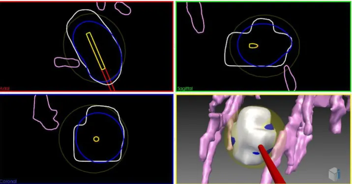
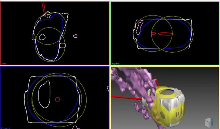
In a study by Butz et al., [15] a software tool is presented based on 3DSlicer for preoperative planning of cryosurgery which can be extended to laser and radiofrequency ablation. Moreover, arbitrary virtual ablation devices can be added to the 3D scene and can be visualized using surface models. Ablation zones are modeled using a theoretical geometry. For cryoablation, the frozen vol-umes at the tip of each cryoprobe are approximated by ellipsoids. Geometric parameters of ellip-soids are calculated from previous patient cryoablations. The utilized optimization algorithm is based on the Powell method and in order to avoid dangerous trajectory placements they used a non-linear term inside the objective function. However, the authors do not describe how the insertion zone is computed and which organs are considered for this region (see Figure 2-2).
![Figure 1-5 Avoiding risky regions is shown for cryosurgery planning. Ribs, vessels and spine are avoided taken from [10]](https://thumb-eu.123doks.com/thumbv2/123doknet/14503112.528231/23.892.243.675.185.457/figure-avoiding-risky-regions-cryosurgery-planning-vessels-avoided.webp)
![Figure 1-7 Approximated deformation of ablation region in RFA [13]](https://thumb-eu.123doks.com/thumbv2/123doknet/14503112.528231/24.892.93.801.130.417/figure-approximated-deformation-ablation-region-rfa.webp)
![Figure 2-3 2D bubble-packing results and the corresponding simulated temperature field for three cases [42]](https://thumb-eu.123doks.com/thumbv2/123doknet/14503112.528231/35.892.195.706.123.733/figure-bubble-packing-results-corresponding-simulated-temperature-field.webp)