s%, INST.
by 17 SEP 1935
OSRARl~
Leslie E. Ri chardeon,Lieut.Jjg.
(CC)
U.S.N.Submitted in Partial Fulfillment of the Requirements for the degree of Master of Science from the Massachusetts Institute of Technology,
1935
Course XIII-A
Signature of
AuthoQ-Signature
redacted
Certification of Department _. Chairman of Graduate Committee Professor in Charge
-Head of the Department
Cambridge, Mass. Ilay 16, 19:35.
Professor George W. Swett,
Secretary of the Faculty,
Ylass. Inst. of Technology,
Cambridge, Mass.
Dear Sir:
I submit herewith a thesis entitled
"AERODYNAYIIC IINVESTIGATION OF A ITULTIPLACE FIGHTER" in partial fulfillment of the reouirements of the degree of Master of Science from the Massachusetts Institute of Technology.
Respectfully,
Signature redacted
( ' Leslie E. Richardson
The author wishes to express his
ap-preciation to Proflessor 0. C. Koppen of the Aeronautical Engineering Course for his
interest in, and for the many valuable
sug-gestions given during, the preparation of
this thesis. He is also indebted to Professor Shatswell Ober for Counsel and assistance.
TABLE OF CONTENTS
Page Purpose . . . . . . . . . . . . . . . . . .
Weight estimates . . . . ... .... Dimensions, areas, etc.
Estimate of horsepower required . . .
Take off . . . ... Propeller selection . ... 1 2 4 5 6 Horsepower calculations ... Longitudinal stability . . . . . . . Lateral stability . . . . . . . . . . Velocity in vertical dive . . . . . . Lateral stability in vertical dive.
Aileron rolling moment and angular velocity of roll . . . . . . Rate of roll due to rudder . .
Design of elevator . . . . . . . . . Trimming of tabs on elevator in verti
7 12 15 18 19 . . . 21 . . .
23
. . . 24 cal dive 26Rudder tab angle necessary at spped of
best climb with one engine cut out . . . . .
Discussion and conclusions . . . . . . . . . 27 28
PURPOSE
The purpose of this thesis is to in-vestigate certain aerodynamic characteristics of a low wing fighter monoplane, multiplace (3),
with two engines.
In the following investigation it is not to be assumed that the characteristics as determined are deemed to be satisfactory in every instance although some revision was made from time to time to try and improve certain features.
For the time available, it was considered best to determine, in a general way, what might be
expected from an airplane designed to fulfill certain requirements rather than to be constantly revising the design to achieve the best results in certain particular characteristics.
The requirements referred to were
ar-bitrarily chosen to include a landing speed of sixty miles per hour in still air and an overall wing span of less than sixty feet. These would be requisite for operation aboard a carrier.
IVEIGHT ESTIMATES
Useful Load
Crew of 3 with parachutes
Gasoline (3 x 2 x 550 x .50)
Oil (31 x 2 x 550 x .035 + 8 x 7.75)
Ordnance
3 machine guns with mounts
2400 rounds ammunition bombs and bomb rack Equipment
Radio (two way)
Fire extinguishers (3)
Safety Belts & Live Preservers Total useful load
Weight Empty
1. Structure
A. Wings complete (2 x 533) B. Tqil group complete (110 x 1) C. Body group Fuselage (43 x 12 x 1.5) Landing Gear Tail Skid 600 1924 197 192 726 650 50 24 21 4384 lbs. 1066 110 774 400 20
A. Engine group 2370
& Motors dry 1950
2 Propellers and hubs 220
Exhaust system 40
Controls 30
B. Fuel System (Z21 x 1.0) 321
C. Lubricating System 50
D. Starting and ignition
2 Starters 60
2 Generators 40
Battery and box 50
III. Fixed Equipment and miscellaneous
Instrument board & instruments 30
Surface controls 60
Flooring 30
Firewall 10
Miscellaneous 275
Total weight empty 5536 + total useful load 4384 Total weight 9920
-4-Dimensions, areas, etc.
Length = 516" = 431.0 Span = 678" = 56'.5
For landing speed of 60 m.p.h at sea level with C0 (flaps) = 2.0, (flap angle 450)
Wing area, S 2.0 x 9.3 - 533 sq. ft.
(56.5)2_
Aspect ratio, wing, 533 6.00
Mean chord, wing, = 113"' = 9.42
L = length from c.g to rudder post = 318" = 26t.5
Vertical tail surface = 31.9 sq. ft. Horizontal tail surface = 75.0 sq. ft.
9920 = 18.6
S 533
- 9920 = 9.01 H.P. 1100
Vertical tail surface required : (Diehl)
S"= 6 x 10-5 X 9920 x 56.5 - 31.9 sq. ft. 0.0015 (26.5);
Estimate of Horsepower required
Assume Vmax = 210 m.p.h at sea level
CL = = 9920
Sq 53 x 113.5 = 0.164 Cdprof = 0.0105
Estimated parasite drag coefficient = 18.6 X .008 = .0149
Cdi = (0.164)2 = .0014 10 d-x 6.0 H.P. required = 210 x 533 x 11Z.5 x .0268 375 = 908 H.P. available = 1100 x .80 880
Vmax at sea level will, therefore, be about 210 m.p.h
Take off
Take off distance =
X 200 x 18.6 - 3720 -75-1 7.43 8 .9 200W 75 -1 P 501 ft. (Warmer)
L =
Cj
,
e
s v
2 9920 = 12.40 = q 1.5 x 533 Wind speed Take off speed.. Take off speed = 69.0 m.p.h = 3 = 0.435
69
From Diehlits chart, Ground run into wind = 0.32 Ground wind into calm
-6-Propeller Selection
The selection of a satisfactory propeller to absorb the power from an engine supercharged to 20000 ft., with a plane velocity of about 260 m.p.h is ex-tremely difficult. Little published information is available for propellers operating at the resulting high values of CS and Q
Engine delivers 550 h.p. @ 2200 r.p.m. at 20000 ft.
A geared propeller must be used to avoid tip speed
losses. For 3 blades:; .70 x 550 = 385 gearing 3:2 gives 1467 R.P.M. Assume Vmax = 260 m.p.h at 20000ft. =S 0.638 x 260 0.638 x 260 =24 C 85 - /5 X (1467)2/5 3.73 X 18.54 2.40
Select a propeller with - 370 giving a~n- = 1.50 D - 88 x 260 10.4 ft.
1467 X 1.5
NOTE* For the charts used (unpublished N.A.C.A.) a
correction is necessary to convert the propeller efficiencies given to propulsive efficiencies. This correction was worked out to be
.89 - .76 = 14.6%
.89
Diameter correction
=
.0194 -mThe propeller selected was a standard peller (Navy drawing 4412) which, for high speed pro-pellers has a low constant geometrical pitch. It would be better to have a constant geometrical pitch
of say about 250 and then turn the propeller from that
point.
Horsepower available at sea level
By the use of a "constant speed" controllable
pitch propeller, the r.p.m remains constant.
CS . Ei'V 2/ .638 V -004 Cs =(385)-.//D (1467) 3.29 x 18.54 .01045 V V 88V - .00577 V ND 1467 X 10.4 C v .01045 .00577 1 Cs (1) 2.20 (2) 1.90 (3) 1.60 (4) 1.30 (5) 0.90 ST 1.216 1.050 0.884 0.719 0.497 28.7 26.5 24.5 22.3 21.5 Propeller Efficiency .872 .899 .908 .890 .770 Propulsive Corrected(for Efficiency n dia. amd 3 .745 .741 blades) .768 .764 .775 .770 .760 .756 .658 .657
-8-(1) V a JND = 1.216 x 1467 x 10.4
=
210.5 T.H.Pa e 1100XO.741:815 88 88 (2) V=
173.1 x 1.050 = 181.9 T.H.Pa = 1100-.764=841 (3) V = 173.1 x 0.884 153.1 T.H.Pa = 11OOxO.770.848 (4) V 173.1 x 0.719 124.6 T.H.Pa - 11OOxO.756=831 (5) V 173.1 x 0.497 86.1 T.H.Pa 1100x0.657=723Horsepower available at 20000 feet
Cs .638 x V .638 V 0.00922 V (38511/5(1467)2/5 3.73 x 18.54 J - 88 V - 0.00577 V 1467 x 10.4
CS
J___ ____ 0.00922 0.00577 00J
C 1.598 Propeller (3 efficiency Propulsive efficiency Corrected n 2.40 2.10 1.80 1.50 1.10 1.502 1.314 1.128 0.939 0.689 V = 173.1 x V 173.1 x V 173.1 x V = 173.1 x V = 173.1 x 37.0 35.3 33.5 32.0 31.6 1.502 1.314 1.128 0.939 0.689 0.880 0.892 0.880 0.848 0.650 0.752 0.762 0.752 0.724 0.555 = 260.0 T.H.Pa= 1100 x = 227.5 T.H.Pa * 1100 x 195.1 T.H.Pa 1100 x 162.7 T.H.Pa: 1100 x = 119.2 T.H.Pa 1100 x 0.748 0.758 0.748 0.721 0.557 0.748 - 823 0.758 835 0.748 . 823 0.721 = 793 0.557 613 C J (1) (2) (3) (4) (5) (1) (2) (3) (4) (5) .. N.WHorseiower required at sea level = 125 (I)2
1
V m.p.h Vm.ph x 1.47 - () 2 X550 b 1 X ZVmp.h (9920)2 X 1 - 10290 H.P-ind 56.5 X3 ~ v V H.Pind 212 48.5 200 51.4 180 57.1 160 64.3 140 73.5 120 85.8 100 102.9 80 128.6 CL= W 18.6 Sqs
CLU, at Vmax Parasite dra = 18.6 = 0.161 115.4g coefficient at Vmax max - 18.6 X 0.0076 10 = 0.0142 H. P - ind
-10-CL CD prof 0.161 0.0085 0.181 0.0085 0.224 0.0087 0.282 0.0089 0.372 0.0090 0.503 0.0100 0.727 0.0110 1.128 0.0167 H 212 x 533 x 115.4 x 0.0227 375 200 x 533 x 103.0 x 0.0227 . 375 180 x 533 x 83.1 x 0.0230 375 160 x 533 x 66.0 x 0.0235 375 140 x 533 x 50.0 x 0.0238 375 120 x 533 x 37.0 x 0.0249 375 100 x 533 x 25.6 x 0.0262 375 80 x 533 x 16.5 x 0.0342 375 .P.required
par+ prof. H.P.req.
791 840 665 716 490 353 237 157 95 64 547 417 311 243 198 193 V 212 200 180 160 140 120 100 80 q 115.4 103.0 83.1 66.0 50.0 37.0 25.6 16.5 B 1.00 1.00 1.01 1.03 1.04 1.05 1.07 1.23 CD par 0.0142 0.0142 0.0143 0.0146 0.0148 0.0149 0.0152 0.0175 prof. V 212 200 180 160 140 120 100 80 CDpar + 0.0227 0.0227 0.0230 0..0235 0.0238 0.0249 0.0262 0.0342
Horsepower required at 20000 feet 0' = 0.533 212 200 180 160 140 120 100 80 X 1.37 I! IT tl it Vt
1
0.730 yO~.5338 0.730 290.6 H. P.reCL 274.0 " 246.5 " 219.2 " 191.8 " 164.5 "V 137.0 " 109.7 " = 840 X = 716 X = 547 X = 417 X = 311 X = 243 X = 198 X = 193 X = 1.37 1.37 it IT " " 1150 981 750 571 426 333 272 264 V = V = V = V = V = V = v = v =
-12-Longitudinal Stability*
T
2 U h 6. 00
At maximum speed, horizontal flight, and 20000f t. altitude 9920 32.2 X 0.0006Z4 X 533 X 377 Mean chord = 9.42 C-L = - 9920 = - 0.206 0.000634 X 533 X (Z77)2 q = 0.000634 X (Z77)2 = 90.20 CD = - (0.0227 - C) = - 0.0227 - (-0.206)2 0.0250 1TR 6 T Zu =2 (-.206) =-0.412 d CL=7 -5.70 xlTx 6 = -107.6 do W 6TT - (-5.70) 24.58 - 4.38 L = - 26.5 a = + 35" d = + 15" h = 108" 18.6 0.000634 x 32.2 x 26.5 =34.4 dCD -_2 (-0.206) (-4.38) = - 0.0956 61IT = d = d C. - CL = - 0.0956 - (-0.206) + 0.1104 CD = Ct at o< = 0
dCD
= d Ct at CL= 0 X= 2 ( -. 0250) - 0.62 (0.0250) = -. 0500 - 0.0155 X(= - 0.0655* For definition of symbols used, see notes on "Airplane
Stability and Control" by Professor 0.C.Koppen.
703 (dCL - 5.7 X 77 X 4 3.92 doc Rq-4 4
r
+ 5.7 r - 2 X 533 2 X (- 0.206) (-0.0250) 1.62 - 0.62]
gX (10.4) -0.206 r - 1 = + 0.0785 r = 1.0785 (f = 1.038Q
=.95 -1 = 0.038 75 -0.141 S 533Assume tail efficiency of .85
mq (3.92) (0.141)
(0.098)
+ 0.95 x 0.0383 mq = - 6.16 Udr -2 x 533 (-0.206) (-0.0250 0.62 -3.24
du (104)-0206 0.6 L.24 = 0.205 U .0989 0.06 -(-0.206)1 3-0.9.)-.0205 x 1 2 ( 25) M"770989 13 13-265"1U.0946(assume Ct = CD for very small angles of.
)
mu, - 0.0508 9.42 x 0.95(-0.205) 0.0989 -26.5 1.075 MU - 0.0331 mw .1 9.42 1.25 0.0 9891-4.38 x-26.5(.31-.25)-o.ll4 --26.5-3.92(0.141)(0.85) _( -4.3 8 m =10.1 + 0.094 + 0.005 - 0.298J mw = 10.1 x (-0.199) = - 2.01 10 = 0-14-P = - (-0.o06) (34.4) (-2.01) (-0.412) - (-0.206) (34.4) (-0.33?(+4.38) E = 5.88 - 1.03 = 4.85 C = (-0.0655)(-4.38)+(-0.0655 - 4.38) (-6.16)-34.4(-2.0l)-(-0.412) ,(O.1104) C = + 0.287 + 27.27 + 69.24 + 0.04 C = 96.94 4.85 96.94 2 1' 0. 0500 2 7r = 28.0 units 0.224 period = 28.0 x 2.418 = 67.6 seconds p
Lateral Stability
At maximum speed, horizontal flight, and 20000 ft. altitude Unit of length =
I
= 28.25 18.6 0.000634 x 32.2 x 28.25 T = 2.418 (same as long.) = 32.4For oscillation in roll and yaw = 0 CC E ( --1) .( T- ) -4 B D B;&-C period of oscillation,= 2Vf
assume "a" = 0.06 and "C" = 0.115 (weight distribution factors)
W
0 U= 0i =
-
CL]
x
-0.0956 -(0.206)]
L do KC x
1
4 x 0.115
"k" is taken as 4 for low angles of attack (elliptical distribution) P =- 0.1104 x 1 -0.240
4 x 0.115
1 =
cz.
X
1
=-
4.38 x = -- 18.25p d< Ka 4 x 0.06
-16--2 CL = - 2(-0.206) ak 4 x 0.06 assume y S it 31.9 = 533 = + 1.718 = - 0.4 -= 0.060 (dCL = - 5.7 x
i7
x 1.5 26.9 = - 2.58 e)1.5 1.5 Ir + 5.7 10.4 S=( " 2.58 X 2(-26.5) x 0.06 + 1.262 56.5 x 0.115 nr (tail) X (.2 - 2.58 x 0.06 x( -53.0 2 = - 1.183 0.115 56.5 nr (wing) Z CD X 1 - 2(-0.025) 0 -1088 KC 4 x 0.115 .'. nr (total) = - 1.292Now to make E = 0, i.e. Ulane is neutral as regards spiral
stability.
xlr IV K nr
(1.262) (1.718) = lv (-1.292) ny
A =0 B = - (-18.25 - 1.292 - 0.400) + 19.94 C = 18.25 (- 0.400 - 1.29) + (-0.4) (-1.29) + 32.4xl.262-(-0.24) (1.72 C = + 30.84 + 0.52 + 40.85 + 0.41 = + 72.62 D = 32.4(-1.679()-0.240-0.206)-(-18.25) [-(0.4)(-l.292)+32.4(-1.262 +(-0 .240) (1.718) (-a.4) D = + 24.2 + 18.25(41.37) + .16 D = 779.4 I E= 0 2 B or D B D - C2 = 19.94 x 779.4 - (72.62)2 = 15660 - 5270 = 10390 1 C2 5 2 70 -264 20 20
.*. the factors are not sufficiently accurate Taking the equation
Ad4 + B d3 + 0d2 + Dd + E = 0, and setting E =0, we get Ad3 + Bd2 + Cd + D = 0
d3 + 19-.94 d2 + 72.62d + 779.4 = 0
one real root about - 18, i.e. approximately 1P
a f(d)
-18 + 96 by graph, one real - 19 - 259 root = - 18.3
-18-d = - 18.3 factoring, (d + 18.3) (dZ + 1.64d + 42.55) = 0 -1.64 * V2.64 - 4 (42.55) :. d = 2 d - 0.82 \'- 41.88 2 IT _17 eod period-6.4 6 x 2.418 = 2.37 seconds
time to damp to 1/2 period = 9.69 x 2.418
0.82
= 2.03 seconds
Velocity in a vertical drive (i.e. path is vertical CL1 = 0 CD prof CDpar CD flaps CD total 9920 = s2 0<= -100 = 0.0100 = 0.0142 = 0.0400 = 0.0642 0 (split flaps, 0.25c, tapered, tip section,
removed, flap angle 45*)
C D 2 x 9920 533 x 0.0642 x 0.00176 tat 10000ft. V2 = 329000 V = 574 f.p.s = 391 m.p.h
Lateral Stability in Vertical Dive T m 9920 32.2 x 0.0000 x 533 x 574 2 18.6 32.2 x 0.000878 x 28.25 = 23.25 For the quartic eqation:
CD replaces CL in solving fofthe coefficients CD = - 0.0642
w
0 V U @ = 0 dCD- 0 np =0 (CL = 0) "af = 0.06 19 p= -18.25Xas
before) = -0.4 (assumed) (dCL) d r=l.5 nr wing = -2.58 = 2(-0.0642) 4 x 0.115 nv = + 1.262 (as before) = - 0.279 = - 1.183 (as before) = 1.462 1.679 = 1.145 "c It = 0.115 :r tail nrtotal 1v =- -20-A =-1 B = -
(18.25
- 1.462 - 0.4) = + 20.11 C = - 18.25 (-0.4 - 1.462) + (-0.4) (-1.462) + 23.25 (1.262) C = 34.00 + 0.58 + 29.40 = + 63.98 D = 23.25(-1.679)(-0.0642)-(-18.25) -0.4(-1.462) + 23.25(1.262)7 D = + 2.50 + 18.25 x 29.98 = 549.7 E = 23.25 (-0.0642) - (-1.679) (-1.462)] E =+ 3.67The factors are not sufficiently accurate
sinceE
ft
1 B or D and B D - C2d4 + 20.11 d3 + 63.98 d2 + 549.7 d + 3.67 = 0
To facilitate solving this equation, E can be
assumed = 0, without appreciable error. Actually, this root equals (aDproximately) - 0.0067 instead of the assumed 0.
Now, d3 + 20.11 d2 + 63.98 d + 549.7 = 0
d f(d) -18 + 85 - 18.2 + 16 - 18.3 - 15
Taking d = - 18.3 as one root and factoring, (d + 18.3) (d2 + 1.81d + 30.0) = 0 d = - 1.81
*
d = - 0.91V_3.28
- 4 (30) 2 V- 29.18 period = 2 4 x 1.145 5.40 = 1.33 secondstime to damp to 12= 0.69 x 1.145 = 0.87 seconds
0.91
The period is very short, but because of the excellent damping, is satisfactory.
Aileron rolling moment and angular velocity of roll at
Vma,. horizontal flight, 20000 ft.
Ailerons are differential and balanced at 201 of the chord.. Aileron chord 0.25 of wing chord and span = 0.40 b
2
Assume a stick force moment of 100tlbs. For a similar aileron but unbalanced, this would correspond to a moment of 300 ft. lbs.
Hinge moment H = CH q c s
where CH = absolute coefficient q = dynamic pressure
c = wing chord in feet S = wing area, square feet
C300 = 0.000662
Hr 90.25 x 9.42 x 5Z3
The differential aileron used (similar to Fig.3, No. 1 N.A.C.A. Technical Note 449) with aileron angles
of 3%0 will give this coefficient. Each aileron is de-flected 3?0 here because the differential action is not yet apparent at such low angles.
-22-From N.A.C.A. Technical Notes 449, C1 = 0.007 + 0.003 = 0.010
Rolling moment = 90.25 x 56.5 x 533 x 0.01 = 27200 ft. lb.
dL
1 (dc u
where c = wing chord in feet
b=
wing span in feetU= speed in ft; sec.
dL
0.000634 x 4.38 x 9.42(56.5)3 377dL
- 111200 ft. lb. d'P pIL = 27200 dip- p 27200 0.244 radians per second
111200
Check on the value of "p"
L
l.p
= d L x 5T dp A
d L -A .1
.'. d p g T
From Technical Note 375,
A= 0.017 x 992 (9.02 + 56,52) = 17150
Also, (to check), A = 0.06 x 9920 56.5)2 14750 32.2 A
where 0.06 was the assumed value of "at XL
',IL = 17150 x 18.25 =
129700 2.418
P = 27200 = 0.210 radians per second
129700
or using, A 14750 9
p = 27200 = 0.244 radians per second 111300
which is the same value as obtained by the first calculation:
Rate of roll due to rudder, horizontal flight, Vmax, at 20000?. Make t = 0.65 and assume rudder angle of 50
C = 1.90 x o.65 - 0.57 (0.65)2 - 0.014 x 5 x 0.65 1.24 - 0.24 - .05 = 0.95 TO= 0.95 x 5 = 4?75 Lateral force = 2.58 x 4.75 x 90.25 x 51.9 57.3 = 616 lb. Yawing moment = 26.5 x 616 = 16320 ft. lb. v = yawing moment dv NV x T L =n N v n.. = d N TL C d v dN _
C
x nvZ dv TLC
= c m b2 0.115 x 9920 x (56.5)2 4 32.2 4 28300 Checking by T, N, 375 C = 0.018 x 9920 (43.02+ 32.2 27950-24-dN - 28300 x 1.26 = 520 dv 2.42 x 28.3 v dN = 16320 (yawing moment) dv v = 16320 31.4 ft. per second 520 Lv x T L lv L lv - dL S TL- A dv dL
A
lV= 14750 x 1.68 = 362 dv g TL 2.42 x 28.3 dL p dL dv dp 31.4 x 362 = p x 111000. p = 31.4 x 362 = 0.102 radians per second 111000
The rudder hinge moment (rudder balanced at 20% of the chord) necessary to give the above 50 rudder angle is = 0.0135 x 90.25 x 31.2 x 4.2
= 161.2 ft. lb.
where 0.0135 = hinge moment coefficient 90.25 = q
31.- = rudder area
4.2 = rudder mean chord
Design of elevator (3 - point landing)
It is desired that the plane stall with 180 up
elevator, 270 being the maximum deflection of the elevator. The following determination of the t ratio is made with
the flaps up. The airplane moments are more readily
obtained in this condition and a plane which lands factorily with the flaps up, will be found to land
satis-factorily with them down.
Stalling angle = 180, CL = -1.50 CD = -0.170 C-Al= -0.06 = 0.141 S k = 0.25 d c aI 35 - 0.310 c 113 = 15 - 0.133 113 d = + 15" c = 113 = 0.355 L 318 dCL)" =- 3.92 (radians) = -0.0685 (degrees) Ct - 0.170 (0.951) - (-1.50 x 0.309) - 0.162 + 0.465 + 0.303 CL C: = - CL 2 ( -k) + Ct
L
d L L c L c S (L is + here) C -0.06 (0.355)-(-1.50)(0.355)(0.06)+(0.303)(0.355)(O.133) 0.141 -0.0213 + 0.0319 + 0.0108 = 0.141 0.02140.141 CL = - 0.152 -0.152 -0.0685 = + 2?22 0.25 x 1.50 x 57.3 6 f 2.22 = 18 -3.58 + oc e =358 K = 0) - 12? 2 - 12.2 18 1.90 - 0.57(t) 2 -0.014 x 18 x t 11 -c c oC-26-"0.678 = - 0.57 (t )2 c + 1.73 t (t)2 -. 0 4 + 1.19 = 0 c c t - 3.04 \9.25 - 4.76 - 3.04 - 2.12 = 0.46 c 2 2
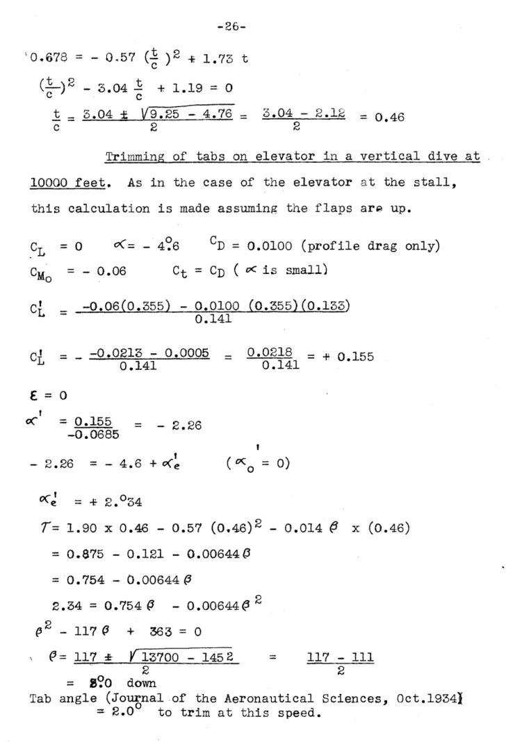
Trimming of tabs on elevator in a vertical dive at 10000 feet. As in the case of the elevator at the stall, this calculation is made assuming the flaps arp up.
CL = 0 (=- 4'6 CD = 0.0100 (profile drag only)
= - 0.06 Ct = CD ( oc is small) -0.06(0.355) - 0.0100 (0.355)(0.133) 0.141 -0.0213 - 0.0005 0.141 oC = 0.155 -0.0685 0.0218 = + 0.155 0.141 = - 2.26 - 2.26 - 4.6 + C(e (CQ = 0) 'Ce = + 2.034
T=
1.90 x 0.46 - 0.57 (0.46)2 - 0.014 (3 x (0.46) = 0.875 - 0.121 - 0.006440 = 0.754 - 0.00644 P 2.34 = 0.754 P - 0.006440 2 02 - 117 P + 363 = 0Q=
117 e 13700 - 1452 2 3 ?0 down = 117 - 111 2Tab angle (Journal of the Aeronautical Sciences, Oct.19341 2.00 to trim at this speed.
CM 0
CL
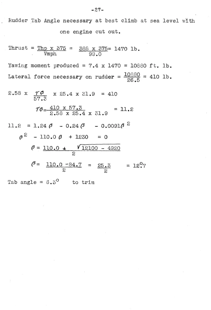
Rudder Tab Angle necessary at best climb at sea level with
one engine cut out.
Thrust = Thp x 375 = 388 x 375= 1470 lb.
Vmph 99.0
Yawing moment produced = 7.4 x 1470 = 10880 ft. lb. Lateral force necessary on rudder = 26.5 = 410 lb.
2.58 x 7V x 25.4 x 31.9 = 410 57.3 410 x 57.3 2.58 x 25.4 x 31.9 = 11.2 11.2 = 1.24 3 - 0.24(3 (2 - 110.0 0 + 1230 (3= 110.0 -1 2 (3= 110.0 -84.7 2 - 0.00910 2 =0 12100 - 4920 = 25.3 2 = 12?7
-28-DISCUSSIOIT AND (ONCLUSIONS
In the performance calculations the two engines were assumed to be supercharged to an altitude of 20000 feet.
The propellers are of the "constant speed" type. As previous-ly stated, the selection of a suitable propeller is a major problem. It is necessary to use very high blade angles. Data on propellers operating on such angles is singularly lacking. The values assumed for the parasite drag of the plane are low, but,it is believed, are a good estimate of what could actually be attained. Wind tunnel tests indicate
that a CL of 2.0 can be obtained with the tapered Clark Y wing section used and with the flaps deflected to 45'.
As regards longitudinal stability, the period is high but it is to be doubted if this can be appreciably decreased. "T" is high, due, of course, to the small value
of
"e"
at an altitude of 20000 feet. A good criterion toinvestigate, time permitting, would be the damping at the
speed of best climb.
The lateral stability calculations show a very short period in both level flight and in the vertical dive but the damping is exeellent. In each case the time required
to damp to J is less than one period. The short period should therefore give no trouble. "lv" was chosen at level flight
-29
-so as to make the coefficient E=0. The root of the factor representing spiral motion is then here equal to zero. The assumed value of yv = -0.4 is considered reasonable. It is to be noted that the nv produced is here due to the vertical tail surface only. The fuselage will alter this somewhat.
The velocity in the vertical dive, calculated for a mean altitude of 10000 feet, was obtained by equating the weight to the drag. The plane will dive with the flaps down. The velocity calculations and the lateral stability calculations were made assuming the flight path to be vertical. This condi-tion may be a bit extreme but the results can be taken to apply, without serious error, to any flight path within a few degrees of the vertical, which condition it was desired to investigate. Actually, the direction of the flight path is somewhat uncertain here since we are operating on a very steep part of the L/D curve.
The angular velocity of roll due to the ailerons is
about what might have been expected but that due to the rudder seems low. A more accurate determination of the moment of in-ertia "C" is probably desirable.
The tabs on the rudder and elevator are for trimming purposes and not fcr balancing. These surfaces are already
7
-At
t-fr4 4 it 71777 I 1, 777-777 ~1:7~ VT ~42.L
A-I--7-71 1 77 7 I -II 7 I 47-774. ..7l777t7~fH7.717.77i77.17~7~ -44--I--i .7 7 77177 .7477717 7 I~ <74111
_ __ {717, I I --7 --7 J7 7** 44- -___I______ H+ t NO77777 l/VE -t4 _ ser /eve/ J.4u-e seo/eve/1-1-.-*
, I T7J4.7777U17 71-.~-7 - T7-TV * ~ 7 -i--Vt 111v71;
4-ii -i-I- -4--it,~ 48500
c
600 400 200 /00 /20 /40 4 A1^ I --, -T +- H --r L-T'4-- +~7V+FT7 ii;7-i
UT-tt --1X/Pavolail/e of seQ/eye! w/f one PeUa 1
at20000 ft
tIi _ _ --- _ _ -_ -_- t 44T -- 1 -1ttt 4 - - -il-- -
-f
t74777t7i714TzI~-~ -- ~7
K7IV
1
-T+ 7-
7777777 7 7 7----80
Pr ro1Q/e ta200007.
I ; ; 1 1 1 i i i i 1-L - i i i i i i i ! i i ! I -+I ,CO u 4o 40L ,eoo Z2z /60 /BO..lfIE
I
-- 444-i-I
-4 4 444.L.:.2. 4 14+ii{2+
'H-H4..4
~1-I <~
<7
I ~
49 I ~ ~ -V+-
-w
4-'4.2
.+41r
4 4--
4I-i
'44 .4.
J-_4.
- T 4LL 3*12.i
1141.1744 ~
I 144
~1.t
~
Ii
-1- -f--h-4 / Cit Vmoj4.-I-~
~--r 4. I-I.r.
-1. .1.~1~ -1 .tILI
Hi Cuorve o C 0 II-.411
-44+LIlt'
V-Vt
I~
~1~ I51'K
I7~
~iT
L4 4.4121
tLIA+..
1.
.4. -1 4.I.
4.41.11
4..r
K--.4 J1 Al-/.0 C esat pa-P
~1-~-T 4~4~ -IL4
F
-F
I-
1~.1'
.$1 ~1
1.
4..
~1~~
P1 .4.. 4. 1~1~ -4-4-1----~iL4Li
~ it'V
.11 -4--4-A M .4 III I liT -1. ~ 4.1. 441K.
.1. I 4 44 I.. '1~1*~I
t
F-. .4.41.
-1-p I.$
I-
-1-11
~1-1~~4
~
I
141j4
4 44-1'
4
-i -4.. 4~1
ff~
474.
I
91f
V
Ii
I
'1-
~hi
+ 44-1- _ _'1111
4 14 it-it .7111 -i+
4~l ii'.f__ ii-.1
-H
~1 - -. 4. 4-1~-LI'
-1-~ 2.0 1" 11.*
I'
i-I--4 .1..1-4
-4.Hill-.
7
t
'LI ~
1+17V-K
1+
1. 1T4
~711 -~_4~4illI
I
p1-Ii.
j-.-7 4. .411
I., 41I.-
4
4~1j.
jL17f~
4j
.4..-4.4.... 4.4 4. .11 ~44~ ~41~ '4.4 444 4 .4-[-4
i-A~1
J(or
MUL
7T/PL
lICE
/~/&A/
TEl?
ISc a/e:
/"=40"
/4
0,93 ,57@ - >4
@5 -/OecWorz. oriz. Vert, Vert,
O'bje ct
We Jt 1--, meC1t firm rbieCe/ /orwara'/gunner,;parache,a-clo'e/t
202
44
8690 + 8 /6/6.
Pot, arachute, and belt
202
/40
28Za.80
+8
t /61/3
9fter9unnerpLrachutean
oc/e/f202
285
57600
+ 7 +414/4
4 6aso/n7e
/924
/70
327200
-/7
-32730
5
O//
/97
/00
/0700
-/5
- 2955
6 Fvamac
ineyun &ammunition
306
38
/1620
120
*6/20
7 ,ffter -' "Uns ts C/2 275
/68300
00
&
eomsalc
rock
G50
235 /52700
-22
-/43 00
$ Radio
56-0
70
3500
0
0
/0 fire ex/tnulsbsers24
/50
36000
0
/1 Life
preservers
/
/
0
2250
-/0
-/0
/2 W/ny s comnp/ete
/066
/67
/78000
-8
-
8528
/3 7~-d/ surfac es //.470
51700t30
-t3300/4 Fuse/g e
774
/76
/3
o300
0
0
/1Landing gear
400
/80
72000
-30
-/2000
I 07 ------/4
- 2800
85
/66800
-/0
-/9500
0
67
/4740
-9
-/980
0
//0 3300-5
-/50
_ 834/50
-/ - 600/
/60 S-/400-/6-
-48/5
0
86
5/60
-6
-
360 0 88 3520 -6 - 320 __/00
SOoO
-5
- 2200
75
3000
-/0
-
400
0240
/4400 00
9
//0 330018
+ 5409
1/7
//70 -/0 - /00/60
4800 -20 - 600 5~ /5743200
-9
-2475
0
/554220
-87857
/7orizon9faZ/ a. =/S7fromi caktumn /nae
Vertical c.y
I
=99-o
=7<5 79
e/oW ci'af-t'n /'ae'us
/7
Fwo
e/g7ines _/9/d 7~wo
prop
e /_e.s 2/9
4e
c0n ro/s3
20 Zuj r/cating syste&n
2/
Fue/
ysem
3'
2
Starters
6
23 Generators24 Batteryx6ox
25 Zx-havst -system4_
26 Surface controls _Z7 I,,strume6t oard& /sttrlnen/7s