HAL Id: hal-02882916
https://hal.archives-ouvertes.fr/hal-02882916
Submitted on 28 Jun 2020HAL is a multi-disciplinary open access archive for the deposit and dissemination of sci-entific research documents, whether they are pub-lished or not. The documents may come from teaching and research institutions in France or
L’archive ouverte pluridisciplinaire HAL, est destinée au dépôt et à la diffusion de documents scientifiques de niveau recherche, publiés ou non, émanant des établissements d’enseignement et de recherche français ou étrangers, des laboratoires
Ultra-Stable Magnetic Nanoparticles Encapsulated in
Carbon for Magnetically Induced Catalysis
Luis Miguel Martinez-Pietro, Julien Marbaix, Juan Manuel Asensio, Christian
Cerezo-Navarrete, Pier-Francesco Fazzini, Katerina Soulantica, Bruno
Chaudret, Avelino Corma
To cite this version:
Luis Miguel Martinez-Pietro, Julien Marbaix, Juan Manuel Asensio, Christian Cerezo-Navarrete, Pier-Francesco Fazzini, et al.. Ultra-Stable Magnetic Nanoparticles Encapsulated in Carbon for Mag-netically Induced Catalysis. ACS Applied Nano Materials, American Chemical Society, In press, �10.1021/acsanm.0c01392�. �hal-02882916�
Ultra-Stable Magnetic Nanoparticles Encapsulated
in Carbon for Magnetically Induced Catalysis
Luis M. Martínez-Prieto,1,± Julien Marbaix,2,± Juan M. Asensio,2 Christian Cerezo-Navarrete,1
Pier-Francesco Fazzini,2 Katerina Soulantica,2 Bruno Chaudret2,* and Avelino Corma1,*
1 ITQ, Instituto de Tecnología Química, CSIC-Universitat Politècnica de València, Av. de los
Naranjos S/N 46022, Valencia, España
2 LPCNO, Laboratoire de Physique et Chimie des Nano-Objets, UMR5215 INSA-CNRS UPS,
Institut des Sciences appliquées, 135, Avenue de Rangueil, F-31077 Toulouse, France.
± These authors contributed equally to this work
E-mails: chaudret@insa-toulouse.fracorma@itq.upv.es
Keywords: magnetic nanoparticles • carbon encapsulation • magnetic catalysis • methanation •
propane dry reforming • propane dehydrogenation
Abstract
Magnetically induced catalysis using magnetic nanoparticles (MagNPs) as heating agents is a new
efficient method to perform reactions at high temperatures. However, the main limitation is the
lack of stability of the catalysts operating in such harsh conditions. Normally, above 500 ºC,
NPs in carbon (Co@C and FeCo@C) as an ultra-stable heating material suitable for high
temperature magnetic catalysis. Indeed, FeCo@C or a mixture of FeCo@C:Co@C (2:1)
decorated with Ni or Pt-Sn showed good stability in terms of temperature and catalytic
performances. In addition, consistent conversions and selectivities regarding conventional heating
were observed for CO2 methanation (Sabatier Reaction), propane dehydrogenation (PDH) and
propane dry reforming (PDR). Thus, the encapsulation of MagNPs in carbon constitutes a major
advance in the development of stable catalysts for high temperature magnetically induced
catalysis.
Introduction
Magnetic heating is an attractive alternative to conventional heating that has been gaining
attention in catalysis during the last years. Indeed, magnetically induced catalysis using magnetic
nanoparticles (MagNPs) has been succesfully applied in solution1-6 as well as in gas-phase
reactions.7-14 It is based on the principle that ferromagnetic materials can release heat to the
environment through hysteresis losses in the presence of an oscillating magnetic field. The main
advantage of magnetic heating relies on the very fast warming up of the system, which makes this
system adapted to the storage of intermittent energies, as well as on the direct heating of the catalyst
without the need for heating the whole reactor.15 This makes magnetic heating a promising method
to perform reactions that occur at medium/high temperatures, such as CO2 methanation (Sabatier
Reaction), propane dehydrogenation (PDH) or propane dry reforming (PDR). The heating power
of MagNPs is commonly quantified by the specific absorption rate (SAR), which measures the
energy released per unit of mass upon magnetic excitation. In particular, when applying an
The current context of global warming has stimulated the development of catalytic reactions that
utilize CO2 as a platform molecule for the production of fuels or chemicals, with the objective of
reducing the global carbon footprint. CO2 hydrogenation (the so-called Sabatier reaction) (Eq. 1)
is one of the main synthetic routes to produce methane. Although it is an exothermic reaction, it is
usually performed above 250-300 ºC, due to the high kinetic barrier for the activation of the CO2
molecule,17-19 and development of catalysts able to work at lower temperature is an important
issue.20 Even if Sabatier reaction is presently exploited at industrial scale, it requires an important
energy supply to reach the operating conditions. This is one of the limitations of Power-To-Gas
(P2G) technology, where the excess of electricity is used to produce methane.21 Therefore,
energetically efficient processes that can be rapidly started or stopped are of high interest due to
the possibility to carry out the hydrocarbon production only when the weather conditions allow it.
In this context, magnetic heating can be an interesting alternative for intermittent energy storage
or P2G. On the other hand, a catalyst displaying good magnetic heating performances would
enable to perform more efficiently endothermic reactions that require high-energy supplies. Since
the catalyst itself, and not the reactor, is the heating source, the energy transfer is rapid and
efficient. Another reaction of industrial interest is the endothermic dry reforming of propane
(PDR), which can be a solution to the increasing demand of synthesis gas (CO, H2) or the hydrogen
production for industrial applications.22 Similarly, dehydrogenation of light alkanes (e.g. propane)
has received great attention because of the growing need of light olefins for the production of
chemicals.23 These reactions occur at high temperatures, above 600°C in the case of propane
dehydrogenation (PDH; Eq. 2) and from 550°C to 900°C for propane dry reforming (PDR; Eq.
3).22,23 Dry reforming is generally catalyzed by Ni-based catalysts,24 while PDH is catalyzed by
The Curie temperature (Tc) is the temperature at which a ferromagnetic material becomes
superparamagnetic, hence losing its magnetic heating capacity. Thus, the composition of the
heating agent is of high importance as the Tc of the MagNPs defines the highest temperature that
can be theoretically attained by magnetic induction. Therefore, a precise control of the Tc of the
heating agents will determine their further applicability in the magnetically-induced catalysis of
various reactions, when associated to appropriate catalytically active phases. In a recent
publication, it has been reported that iron and iron carbide NPs are inefficient to activate high
temperature catalysis by magnetic heating while FeCo NPs reach temperatures high enough to
significantly activate PDR and PDH.10 However, especially in cases where high temperatures are
required, a main limitation of magnetically-induced reactions is the lack of stability of the catalysts
that need to be active for long reaction times under harsh conditions. It was observed that, for
temperatures above 500°C, massive sintering of both heating and catalytic nanoparticles occurred,
together with carbon deposition which led to deactivation of the catalyst.10 These processes reduce
both the catalytic and heating properties of the NPs and therefore the magnetically-induced catalyst
lifetime. In this respect, metal nanoparticles (MNPs) encapsulated in carbon have emerged as
efficient sinter-resistant materials thanks to their high thermal stability and confinement
properties.28-30
Herein, we present novel heating agents for magnetically-induced catalysis based on magnetic
to the materials the stability necessary to avoid sintering at such high temperatures. FeCo@C and
Co@C were fully characterized by common techniques, such as Transmission Electron
Microscopy (TEM), High resolution TEM (HRTEM), Energy-dispersive X-ray spectrometry
(EDX), Inductively Coupled Plasma (ICP), RAMAN Spectroscopy, X-Ray Photoelectron
Spectroscopy (XPS), X-ray Powder Diffraction (XRD), Temperature-Programmed Reduction
(TPR) and Vibrating-Sample Magnetometer (VSM). In this work we demonstrate that FeCo@C
and Co@C (5 % wt) can be used as heating agents in magnetically-induced reactions taking place
at temperatures above 600 °C, maintaining their morphology and heating capacity. These
ultra-stable materials (FeCo@C and Co@C) have been decorated with Ni or Pt-Sn and evaluated in
methanation, propane dry reforming and dehydrogenation of propane, presenting high stability in
all the cases without modification of their catalytic performances.
Results and discussion
1. Synthesis and characterization
The methodology to encapsulate MagNPs in carbon is based on a two-step procedure. FeCo
prepared by a previously reported procedure31,32 and Co nanoparticles prepared by adaptation of
the same procedure (see Experimental part, section 2) were supported on activated carbon (FeCo/C
and Co/C; 5 wt %). Then, the MagNPs were encapsulated in carbon through a pyrolysis process
(600 ºC, 2 h, 10 ºC/min) to afford FeCo and Co NPs covered by a narrow carbon layer (Figure 1;
FeCo@C and Co@C). The detailed synthetic procedure is described in the experimental section
(see Experimental part, section 2). The metal contents of FeCo@C and Co@C were determined
by ICP Atomic Emission Spectroscopy (ICP-AES). Specifically, FeCo@C (Fe: 2.6 wt% and Co
2.3 wt%, corresponding to a NP composition of Fe54:Co46) and Co@C (Co: 4.8 wt%) presented
Figure 1. Synthesis of FeCo@C and Co@C following a two steps synthetic procedure: (i)
formation of FeCo/C and Co/C by the immobilization of MagNPs on activated carbon (24 h stirring
at room temperature) and (ii) pyrolysis of FeCo/C and Co/C (2h at 600 ºC under N2 flow, 10
ºC/min).
TEM analysis of FeCo and Co NPs before encapsulation show spherical and well-distributed
nanoparticles, with a good dispersion and a main diameter of ca. 10-11 nm (see SI, Figures
S1-S3). The size and morphology of FeCo@C (10.1 ± 2.0 nm; Figure 2, a-c) and Co@C (10.5 ± 1.9
Figure 2. TEM micrographs and illustrations (insets) of FeCo@C (a-b) and Co@C (d-e) with
their corresponding size histograms [FeCo@C (c) and Co@C (f)].
The morphology, composition and crystallinity of FeCo@C and Co@C were studied by
High-resolution TEM (HRTEM), Energy-dispersive X-ray spectrometry (EDX) and Scanning
transmission electron microscopy (STEM) using a high-angle annular dark-field detector
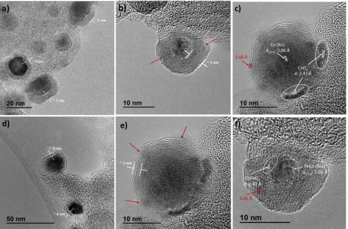
(HAADF). HRTEM micrographs indicate the existence of crystalline NPs encapsulated by a
carbon layer with a thickness between 2 and 5 nm (Figures 3a-b and 3d-e). This carbon layer
possesses a double function: i) protecting the magnetic FeCo and Co NPs from full oxidation by
air, and ii) preventing their sintering under the high temperatures reached under catalytic
conditions.However, the carbon layer is not continuous over the whole nanoparticle, since it
presents some gaps or cracks (Figures 3b and 3e). The presence of these cracks was corroborated
(for more details see Experimental part, section 6). The carbon-encapsulated Co nanoparticles
(Co@C) exhibit an fcc cobalt core with a lattice spacing of 2.06 Å that corresponds to (111) plane,
and cobalt oxide (CoOx) regions on their surface with a fringe spacing of 2.42 Å, which belongs
to (113) plane (Figure 3c). Similarly, the core of FeCo@C NPs presents a bcc structure with a
lattice spacing of 2.03 Å with some oxide at the surface (Figure 3f). The cracked carbon layer
explains the partial oxidation of Co@C and FeCo@C NP surface after exposure to air. In both
systems, the space between the carbon layers is around of 3.6-3.4 Å (Figures 3c and 3f), which
corresponds to a turbostratic ordering of the carbon.
Figure 3. HRTEM micrographs of Co@C (a-c) and FeCo@C (d-f). The cracks of the carbon layer
are highlighted by red arrows (b, e). The lattice spacing of Co and FeCo NPs are in white and the
Figures S4 and S5 (see SI) show STEM-HADDF images, and EDX analysis of Co@C and
FeCo@C, respectively. EDX mapping of carbon, cobalt and oxygen elements within Co@C
(Figure S4a-d) confirms the partial oxidation of the enclosed-Co NPs. Elemental mapping of
FeCo@C demonstrates the bimetallic nature of these NPs (see SI, Figure S5a-d), with an atomic
composition of Fe47:Co53 (see SI, Figure S6), which agrees with the theoretical composition
(Fe50:Co50), and match with the ICP results obtained (vide supra). In the EDX composition
profiles, we can observe that both MagNPs are embedded either in a thin carbon layer (e.g. 1-2
nm, Figures 3b and 4e) or in a thicker one (e. g. 4-5 nm; Figures 3e 5e).
Figure S7 (See SI) shows X-Ray diffraction (XRD) diffractograms for Co@C and FeCo@C.
Both materials present a (002) peak at 2θ = 26.4º with an interlayer separation of d = 3.36 Å, which
corresponds to the carbon material. In addition, Co@C XRD exhibits fcc-Co and CoOx peaks with
relatively low intensities due to the low metal loading (~ 5%). FeCo@C XRD also presents some
minor peaks, which correspond to bcc FeCo and FeCo oxides (FeCoOx). XRD confirms the partial
oxidation of the MagNPs encapsulated by the cracked carbon layer when they are exposed to air.
These results are in good agreement with HRTEM and EDX observations. Raman spectra of
Co@C and FeCo@C NPs (see SI, Figure S8) display two major bands at 1313-1307 cm-1 (D peak)
and 1600-1595cm-1 (G peak), associated to carbon materials.34 The high intensity of the D peak is
related to the large percentage of disorder present in these carbon materials. The region between
200 and 800 cm-1 of Co@C spectrum exhibits the typical vibrational modes of Co
3O4 (3F2g, Eg,
and A1g) at 194 (F2g), 474 (Eg), 517 (F2g), 619 (F2g) and 691 (A1g) cm-1.35 FeCo@C spectrum also
shows the FeCo2O4 vibrational modes but with a lower intensity and slightly shifted to minor
The oxidation state and reducibility of these carbon-encapsulated MagNPs was investigated by
X-ray photoelectron spectroscopy (XPS) and temperature-programmed reduction (TPR). By TPR
we found that the reduction temperatures for Co@C and FeCo@C were 320 ºC and 351 ºC,
respectively (see SI, Figures S9). Figure S10 (see SI) shows the Co2p area of Co@C before and
after reduction by H2 at 400 ºC. The as-synthesized Co@C spectrum presents a main peak at 780.7
eV that can attributed to CoOx species. After reaction at 400 ºC under H2 atmosphere during 4 h,
the CoOx surface was totally reduced to Co0 since the spectrum only exhibits a single signal at
778.4 eV, characteristic of metallic cobalt.37 A similar behavior was observed for FeCo@C (see
SI, Figure S11), where we can see a clear reduction of Fe and Co in Fe2p and Co2p regions,
respectively. These results confirm that the surface of the as-synthesized samples is fully oxidized
but that it can be reduced under reductive conditions, which might increase the magnetic heating
capacity of the materials under operating catalytic conditions.
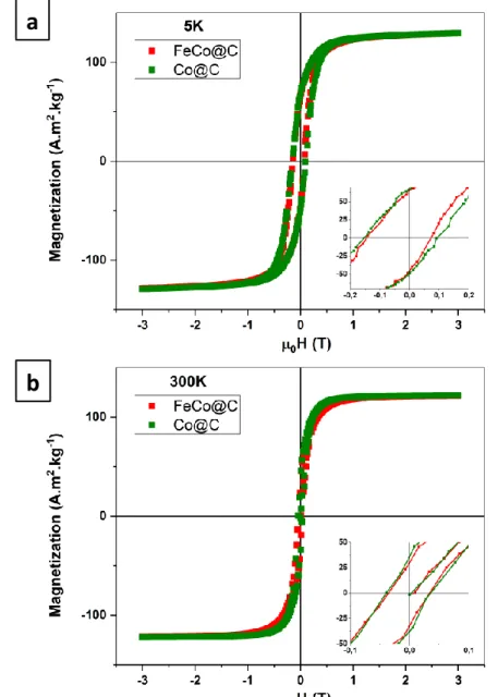
The magnetic properties of Co@C and FeCo@C have been measured by Vibrating Sample
Magnetometry (VSM). Saturation magnetization (Ms) and coercive field (μ0Hc) have been
determined from the hysteresis cycles (Figure 4). For both samples, Ms is close to 120 A·m2·g-1 at
300 K and 130 A·m2·g-1 at 5 K. These values are below those reported for the bulk materials, (230
A·m2·g-1 for bulk FeCo and 165 A·m2·g-1 for Co),38 This reduction can be due to both surface
oxidation and incorporation of carbon into the Co and FeCo lattice during the encapsulation of the
NPs into carbon. Indeed, the formation of cobalt carbide39 or the incorporation of carbon into FeCo
NPs40-41 is known to lead to species showing a depleted Ms. Partial oxidation was confirmed by
the presence of a small exchange bias observed in the hysteresis loops at 5 K after a field-cooling
antiferromagnetic layers.42 However, it is presumably not sufficient to explain the strong depletion
of the magnetic properties which are likely to result from carbon incorporation.
Figure 4. Hysteresis loops measured by VSM on FeCo@C (red) and Co@C (green) at 5 (a) and
300 K (b) with zoomed region between -0.1 and 0.1 T.
The heating power of FeCo@C and Co@C was determined by calorimetry using our previously
described procedure (see SI, section S7).7,43,44 The specific absorption rate (SAR) was determined
in ethanol due to the relatively good dispersibility of the NPs in this solvent (see SI, Figure S12).
a
In both cases, the NPs start to heat after application of a µ0Hrms of 25 mT with a f of 93 kHz, with
a quasi-linear increase of SAR with the field amplitude, reaching 165 W·g-1 in the case of
FeCo@C and 70 W·g-1 for Co@C (see SI, Figure S8). These values are much lower than the
previous ones reported in literature of 1600 W·g-1 for FeCo alloys at 47 mT, 100 kHz.8,10,45 This is
in agreement with the lower Ms and the lower coercivity of these particles compared to reduced
FeCo and CoNPs and are likely due both to the incorporation of carbon into the particles and their
partial surface oxidation. In addition, the particles lack the necessary mobility allowing the
formation of chains which is responsible for the enhancement of the heating power of FeC and
FeCo NPs.10,46,47 However, the measured SAR values can be explained if we consider a metallic
core of the NPs. As a whole, despite the lower SAR, the heating properties of FeCo@C and Co@C
are suitable to heat the system and reach the required high temperatures under catalytic conditions
(vide infra).
2. Catalytic studies
Medium temperature catalysis
Sabatier Reaction.
In a previous work, the catalyst used for the magnetically induced CO2 hydrogenation into CH4
was prepared by thermal decomposition of bis(1,5-cyclooctadiene)nickel(0), Ni(COD)2, in the
presence of Fe2.2C NPs or a combination of Fe2.2C NPs and Co nano-rods (Co NRs) supported on
SiRAlOx.11 The best catalytic results (CO
2 conversions of 90% with a 100% selectivity to CH4 at
a µ0Hrms of 16 mT and a f of 300 kHz) were obtained by using a mixture of Co NRs and Fe2.2C
NPs. Here, the softer Fe2.2C NPs act as pre-heating agents, which activate the Co NRs that have a
magnetic field amplitude to be activated in magnetic heating. Upon pre-heating the Co-NRs, their
coercive field decreases which renders them active as heating agents. Following these results, 10
wt % Ni NPs were deposited on the surface of the carbon-coated heating agent by decomposition
of Ni(COD)2 in the presence of FeCo@C (5wt% in metal; see Experimental part, section 5). This
composition (FeCo@C/Ni) has been used in a continuous flow CO2 hydrogenation using a 1:4
CO2:H2 molar ratio (20 mL·min-1 of H2 and 5 mL·min-1 CO2). 96 % of CO2 conversion with a 98
% selectivity into CH4 was obtained at a magnetic field intensity µ0Hrms = 32 mT and a frequency
f = 300 kHz (Figure 5, Table 1). Decreasing the field amplitude led to lower conversions (91 % at µ0Hrms 28 mT, 98 % selectivity and 55 % at µ0Hrms 23 mT with 61% selectivity). The sample
exhibited a reproducible cyclability over 4 hours and the catalyst was stable for more than 7 hours
(Figure 5). Although higher magnetic field amplitudes were required to achieve the optimal
catalytic conditions than in the case of the Fe2.2C NPs-Ni/SiRAlOx system previously reported, it
should be highlighted that no activation step was required despite the low values of SAR, which
might be related to the higher Tc of Co and FeCo. The temperature of the system, measured by an
ultrathin thermocouple directly located in the catalytic bed,48 increased with the field amplitude
from 230°C at 23 mT to 315 °C at 32 mT. TEM observation showed that the size of FeCo@C/Ni
slightly increased up to ca. 16 nm after 7.5 hours time on stream (TOS) (Figure 5d-e). EDX
analysis of FeCo@C/Ni after catalysis shows signals corresponding to discrete FeCo particles,
indicating the good stability of the heating agents during catalysis. Ni NPs were homogeneously
dispersed thorough the material and did not exhibit extended agglomeration, which may be due to
the global low temperature in the system (Figure 5d-e). Therefore, FeCo@C/Ni has demonstrated
to be an active and stable catalyst capable to carry out magnetic induced methanation without the
the encapsulated nanoparticles, they are able to heat efficiently and do not experience a massive
sintering at these temperatures, as was observed in the same “naked” MagNPs.10
Figure 5. Catalysis of Sabatier reaction using FeCo@C/Ni. Gas flow: 25 ml/min CO2:H2 (1:4). X
a F e K 200 nm 200 nm C o K 200 nm N i K Fe K 200 nm 200 nm C o K 200 nm N i K 100 nm 100 nm 100 nm 100 nm 100 nm 100 nm Fe Co Ni Fe Co Ni b c d e
observation before and (c) after 7.5 hours TOS. (d) EDX mapping of Fe (red), Co (yellow) and Ni
(blue) after preparation and (e) after 7.5 hours on stream. Temperature was recorded by an ultrathin
thermocouple directly located in the catalytic bed and confirmed by IR thermometry.48
High temperature catalysis
Propane dehydrogenation (PDH).
Due to the high Tc values of both Co@C and FeCo@C systems, we then decided to evaluate
them as heating agents for endothermic reactions operating at high temperatures.10 With the
intention to reach the highest reaction temperature, a mixture of 2:1 FeCo@C:Co@C was used as
heating agent. Following our previous observations, FeCo would act as the soft material displaying
higher SAR values, whose role would be to activate hard Co, which possesses a Tc above 1000
ºC. Thus, we experimentally observed that a mixture of 2:1 FeCo@C:Co@C was the optimum
composition for the heating agent to activate catalysis at high temperatures. Concerning the
catalyst we chose Pt/Sn, prepared by a recently published procedure,10 since recent works have
demonstrated that Sn not only can enhance the activity of Pt NPs in propane dehydrogenation, but
also can improve the selectivity and stability of the catalyst.24,49-50 Therefore, Pt NPs (0.35 wt %)
promoted with Sn (0.5 wt %)52 were supported on a mixture of 2:1 FeCo@C:Co@C (see
Experimental part, section 5) and used as catalyst in Propane Dehydrogenation (PDH) (>700°C).
By using an incoming gas of pure C3H8 (flow of 20 mL·min-1), theconversion reached values up
to 11% with 81% selectivity to propene at µ0Hrms 65mT (300 kHz) and a monitored temperature
of 620 °C (Figure 6a; Table 1). The remaining 19 % of selectivity is due to the formation of
methane and propane in a ratio 1:1. When only FeCo@C was used as heating agent in the same
conditions significant lower performances were obtained (see SI, Figure S13). TEM observations
ca. 15 nm after 2 hours TOS (Figure 6b-c, SI). EDX analysis of the sample before catalysis could not clearly identify Pt and Sn due to the low signal as a result of the low catalyst loadings. However,
EDX analysis after catalysis indicates that a slight agglomeration of Pt and Sn, mostly located on
the heating agents, has taken place (Figure 6d). Similar aggregations of Pt over the heating agents
has been also observed in other high temperature magnetically induced catalytic reactions.10,53
Under the same conditions, uncoated FeCo NPs while being able of activating PDH catalysiswith
slightly higher activity, have limited stability due to massive sintering of metallic NPs and carbon
deposition.10 Therefore, the main advantage of carbon encapsulation is the stabilization of the
catalytic system, avoiding sintering of the heating agents.
Figure 6. PDH reaction using 2 :1 FeCo@C:Co@C/PtSn (Pt 0.35 wt %, Sn 0.5 wt %) as catalyst. a b c d Fe Co Pt Sn 50nm 50nm 50nm 50nm 200nm 200nm
performances over time, (b) TEM observation before and (c) after 4.5 hours TOS. (d) EDX
mapping of Fe (red), Co (green), Pt (yellow) and Sn (blue) after 4.5 hours on stream.Temperature
was recorded by an ultrathin thermocouple directly located in the catalytic bed and confirmed by
IR thermometry.48
Propane Dry reforming (PDR)
Propane Dry Reforming (PDR) was performed by using Ni (10 wt %) impregnated on 2:1
FeCo@C:Co@C as catalyst (FeCo@C:Co@C/Ni; see Experimental part, section 5). At µ0Hrms
32 mT (300 kHz), 9% of the incoming propane was converted into CO and H2 with 100%
selectivity using a gas flow of 10 mL·min-1 (3:1 molar ratio CO
2:C3H8). However, upon increasing
the field amplitude to 60 mT, propane conversion was increased to 54% with a 97% selectivity to
CO, very close to the conversion value at the thermodynamic equilibrium (Figure 7, Table 1).54
The conversion values observed can be explained by the temperature increase from 425°C to
620°C, upon increasing the field amplitude. The selectivity toward CO is particularly high. We
propose that this behaviour is related to the encapsulation of FeCo and Co NPs and successful
prevention of parallel reactions such as Fischer Tropsch, which is a typical undesired
side-reaction.55 The temperature of the system remained stable during the 2.5 hours of the catalytic test.
The size of the MagNPs showed again a slight increase after 2 hours TOS (ca. 14 nm). EDX
analysis after catalysis revealed that Ni catalyst NPs slightly migrated toward the heating agents
a
200nm 200nmb
c
50nm Co Fe 50nm Ni 50nmd
e
Figure 7. PDR reaction using 2 :1 FeCo@C:Co@C/Ni (10 wt %) as catalyst. Gas stream: 10
ml/min CO2:C3H8 (3:1). X = conversion, S = selectivity and Y = yield. (a) Catalytic performances
over time, (b) TEM observation before and (c) after 2 hours TOS. (d) EDX mapping of Fe (red),
Co (blue), Ni (light blue) after preparation and (e) after 2 hours on stream. Temperature was
recorded by an ultrathin thermocouple directly located in the catalytic bed and confirmed by IR
thermometry.48
Table 1. Magnetic induced catalysis performances of Sabatier, Propane Dry Reforming (PDR)
and Propane DeHydrogenation (PDH) using FeCo@C and Co@C as heating agents.
[a] Magnetic field applied of 300 KHz.
[b] Conversions at thermodynamic equilibrium were estimated employing the Gibbs free energy
minimization method.48,56-58
[c] Temperatures were measured by an ultrathin thermocouple directly located in the catalytic bed
and validated with an IR camera. Notice that temperatures given are an estimation and the real temperatures at the surface of the catalyst are probably higher.
2. Stability studies
In order to investigate in more detail the stability of our heating agents and of the catalyst under
the harsh conditions employed, we ran PDR over 6 hours. Specifically, we tested 2:1
FeCo@C:Co@C/Ni (10 wt% of Ni) and a gas mixture of 3:1 CO2:C3H8 with a total flow rate of
10 mL·min-1 during 6 hours. We previously showed that after two hours on stream, 52 % yield
could be reached with nearly 100% selectivity for CO, while supported Ni NPs were slightly
agglomerated. Two more cycles with variable magnetic field amplitudes (32 mT, 44 mT, 53 mT,
60 mT) were performed and enabled to show a quasi-perfect cyclability in terms of temperature
reached by magnetic induction of the heating agents (up to 620°C, at µ0Hrms 60 mT, 300 kHz) and
CO yields (Figure 8). This result demonstrates the very efficient encapsulation of the FeCo@C
and Co@C even at high temperatures. The catalytic performances of the sample remained stable
and reproducible for all the field amplitudes tested. However, EDX mapping after 6 hours on
stream shows a more important agglomeration of the Ni NPs, which, however, did not induce any
significant decrease of the catalytic performances (see SI, Figure S14a-c). Then, the sample was
exposed to air and another reaction cycle was performed. This led to a slight decrease of the
temperature reached in the system to 605°C at a µ0Hrms 60 mT, but no significant effects on the
catalytic performances were observed. In addition, the morphology of the sample was not
significantly altered upon air exposure followed by two additional hours on stream (see SI, Figure
S14d). These results demonstrate the encapsulation in carbon, which remediates the catalyst
Figure 8. Magnetically induced Propane Dry Reforming (PDR) performances and temperatures
using 2 :1 FeCo@C:Co@C/Ni (10 wt %) as catalyst at variable magnetic field amplitudes. Gas
stream: 10 ml/min CO2:C3H8 (3:1). X = conversion, S = selectivity and Y = yield. Temperature
was recorded by an ultrathin thermocouple directly located in the catalytic bed and confirmed by
IR thermometry.48
Conclusions
Magnetically induced catalysis can indeed address various reactions and temperature ranges.
Though the weakness of this technique is the agglomeration of the heating magnetic nanoparticles
upon magnetic excitation, we have shown that this problem can be circumvented by confining the
heating NPs in carbon. Thus, we have successfully encapsulated magnetic FeCo and Co NPs in
carbon (Co@C and FeCo@C), which leads to ultra-stable heating agents suitable for high
temperature magnetically-induced catalysis. Combining a series of characterization techniques
such as HRTEM, EDX, XRD, XPS and VSM, we can conclude that Co@C and FeCo@C NPs
A As synthe zed B A er 2h on stream C A er 6h on stream D A er 8h on stream Air exposi on
have a metallic core and an oxidized surface encapsulated by a carbon layer, but that under
reductive conditions similar to those used in the catalytic experiments, the oxidized surface is
reduced.
Catalytic studies have shown that medium (Sabatier 300-400 °C) and high temperature (PDR
and PDH >600 °C) catalysis can be activated by FeCo@C or a mixture of FeCo@C:Co@C (2:1)
with Ni or Pt-Sn supported, with consistent conversions and selectivities compared to traditional
heating sources. Under the conditions employed, we observed a good stability of the heating
agents, in terms of temperature, and of the catalyst as a whole in terms of catalytic performances.
However, a systematic agglomeration of the catalytic NPs (PtSn or Ni NPs) was observed at high
temperature as in classical heterogeneous catalysis. Under the same conditions, the use of naked
FeCo NPs in PDR or PDH did not show stability for more than one hour.10 Thus, the encapsulation
of the heating agent constitutes a major improvement toward the development of stable catalysts
for high temperature magnetically-induced catalysis.
Finally, in the case of PDR, the catalyst showed remarkable cyclabilities of temperature and
catalytic performance, up to 4 times over at least 6 hours. Furthermore, excellent cyclability was
achieved even after exposure to air of the catalysts and/or partial sintering of the Ni NPs.
Experimental Part
1. General considerations and starting materials
Most of operations were carried out using standard Schlenk tubes, Fischer–Porter bottle
techniques or in a glove-box under argon atmosphere. Mesitylene, toluene and tetrahydrofurane
(THF) were obtained from VWR Prolabo, then purified on alumina desiccant and degassed by
(HDA, 99%), Ni(COD)2, (COD = cyclo-octadiene) and Bu3SnH (1M in cyclohexane) were
obtained from Sigma-Aldrich. Pt2(dba)3, [Fe{N(SiMe3)2}2]2 and [Co{N(SiMe3)2}2(THF)]
precursors were obtained from Nanomeps. All the commercial compounds were used as received.
All gasses were supplied by Air-Liquide with the following purity: CO2 Alphagaz N48, H2 N55,
Ar N56, CH4 N55.
Transmission Electron Microscopy (TEM) and High resolution TEM (HRTEM). FeCo NPs, Co NPs, FeCo/C, Co/C, FeCo@C and Co@C NPs were observed by TEM and HRTEM after
deposition on a copper grid of a drop of a suspension of the material in THF. TEM analyses were
performed at the “Servicio de Microscopía Electrónica” of Universitat Politècnica de València
(UPV) by using a JEOL JEM 1010 CX-T electron microscope operating at 100 kV with a point
resolution of 4.5 Å. The approximation of the particles mean size was made through a manual
analysis of enlarged micrographs by measuring a number of particles on a given grid. HRTEM
measurements were performed using a JEOL 2100F microscope operating at 200 kV, both in
transmission (TEM) and scanning-transmission modes (STEM). Energy-dispersive X-ray
spectrometry (EDX) and STEM imageswere obtained using a high-angle annular dark-field
detector (HAADF), which allows Z-contrast imaging. FFT treatments have been carried out with
Digital Micrograph Version 3.7.4.
Inductively Coupled Plasma (ICP): ICP analyses of FeCo@C and Co@C were performed by ICP technique service of the Instituto de Tecnología Química (ITQ), using a Varian 715-ES
ICP-Optical Emission Spectrometer. The samples for ICP were prepared following a digestion method
recently reported.59 In particular, 30 mg of catalyst sample were suspended in 21 mL HCl-HNO 3
15 hours. Then, the solution was cooled down to room temperature (r.t.), diluted with 100 mL of
water and analyzed by ICP.
RAMAN: Raman spectra were recorded using an excitation of 785 nm in a Renishaw In via Raman spectrometer equipped with a Lyca microscopy. The samples (powder) were deposed on
an Al support, and measured in the region between 0 and 3000 cm-1 with a resolution of < 4 cm-1.
X-Ray Photoelectron Spectroscopy (XPS): XPS analyses were performed using a SPECS device equipped with a Phoibos 150-9MCD detector using Mg-Kα radiation (hν= 1235.6 eV) and Al-Kα
radiation (hν= 1483.6 eV) from a dual source. The pressure during the measurements was kept
under 10-9 Torr. The quantification and titration of the spectra was done with the help of the
software CASA, referencing them in base of C1s = 284.5 eV.
X-ray Powder Diffraction (XRD): Powder samples were analysed using a Cubix-Pro PANalytical diffractometer equipped with a detector PANalytical X´Celerator, employing a
X-Ray monochromatic radiation of CuKα (λ1=1.5406 Å, λ2=1.5444 Å, I2/I=0.5).
Temperature-Programmed Reduction (TPR): Micromeritics Auto-Chem 2910 catalyst characterization system with a thermal conductivity detector (TCD) was used for TPR analysis.
Before analysis of the samples (50 mg), they were pretreated at room temperature in flowing He
(10 mL/min) for 20 min. Then, the samples were heated from 25 ºC to 600 ºC at a rate of 5 ºC/min
in a flow (50 mL/min) of H2 in Ar (10 % vol.).
Gas Chromatography coupled to Mass Spectrometry (GC-MS): GC-MS analyses were carried out in a PerkinElmer 580 Gas Chromatograph equipped with a TCD detector and coupled to a
Clarus SQ8T Mass Spectrometer. Reactants conversions, and product yields and selectivities were
calculated by performing a C balance to the chromatograms. The areas of each peak were corrected
Vibrating-sample magnetometer (VSM): Magnetic measurements were performed on a Vibrating Sample Magnetometer (VSM, Quantum Device PPMS Evercool II). VSM studies were
carried out on compact powder samples that were prepared and sealed under argon atmosphere.
2. Synthesis of FeCo and Co NPs
The FeCo NPs were prepared according to literature.60 Fe and Co precursors, [Fe{N(SiMe 3)2}2]2
(180,7 mg; 0.2 mmol) and [Co{N(SiMe3)2}2(THF) (150.5 mg; 0.4 mmol)], were reduced under 3
bar of H2 upon heating at 150 °C for 24 h in mesitylene (20 mL) and in the presence of long chain
surfactants, hexadecylamine (HDA; 386 mg; 1.6 mmol), and hexadecylamine hydrochloride
(HDA·HCl; 333.5; 1.2 mmol), The precursors concentrations were kept at 20 mmol·L-1. The HDA
and HDA·HCl concentrations were 80 and 60 mmol·L-1, respectively. After reaction, a black
solution with the magnetic FeCo NPs stabilized by HDA/HDA·HCl was obtained. A drop of this
solution was deposed on a cooper grid, and the size of the NPs was measured by TEM for at least
100 nanoparticles, which afforded a mean value of 10.7 ± 2.4 nm (Figure S1). ICP: Fe: 2.6 wt%
and Co 2.3 wt%.
Co NPs: Cobalt NPs were prepared as described for FeCo NPs but starting from the Co precursor, [Co(N(Si(CH3)3)2)2,THF] (361,4 mg ; 0.8 mmol). The size of the NPs was measured
by TEM for at least 100 nanoparticles, which afforded a mean value of 11.7 ± 2.6 nm (Figure S2).
ICP: Co: 4.8 wt%.
3. Synthesis of FeCo@C and Co@C NPs
FeCo@C: 920 mg of activated carbon dispersed in 10 mL of mesitylene were added to a Fischer−Porter bottle charged with a suspension of FeCo NPs (78 mg) in 20 mL of mesitylene.
(see SI, Figure S3). Then, FeCo/C was washed with hexane three times, and dried at 60 ºC
overnight. The resulting black powder was then subjected to a pyrolysis process (2 h at 600 ºC
under N2 pressure, with a heating ramp: 10 ºC·min-1), producing the FeCo NPs encapsulated in
carbon (FeCo@C). The size of the NPs was measured by TEM for at least 100 nanoparticles,
which afforded a mean value of 10.8 ± 3.2 nm (Figure 2a-c).
Co@C: Co@C was prepared as described for FeCo@C but using a suspension of Co NPs (76 mg) in 20 mL. The size of the NPs was measured by TEM for at least 100 nanoparticles, which
afforded a mean value 10.7 ± 2.4 nm (Figure 2d-f).
4. Synthesis of FeCo@C and Co@C decorated with Ni and PtSn NPs.
FeCo@C/Ni and FeCo@C-Co@C/Ni catalyst (10% Ni loading) were prepared by the
decomposition of Ni(COD)2 in the presence of FeCo@C or FeCo@C:Co@C (2:1) in mesitylene.
In a typical preparation 156 mg Ni(COD)2 were dissolved in 20 mL mesitylene and 300 mg
FeCo@C or FeCo@C:Co@C (2:1) were added to the solution. The mixture was then heated at
150 °C under Ar atmosphere and vigorous stirring during 1 h followed by 3 washing steps with
toluene. Drying under vacuum enables to get Ni NPs with a mean size of cs. 2-4 nm immobilized
on FeCo@C or FeCo@C:Co@C (2:1). Total amount of collected powder was of ca. 350 mg.
FeCo@C/Pt-Sn and FeCo@C:Co@C/Pt-Sn. Were prepared by adapting a published
procedure.10 For Pt-Sn catalysts (0.5% loading), the catalyst was prepared by mixing preformed Pt
NPs with FeCo@C or a mixture of FeCo@C:Co@C (2:1). In a typical preparation, 6,5 mg of
Pt2(dba)3 in 5 ml of THF are stirred in the presence of 1 bar CO for 20 minutes. The dark brown
mixture formed is evaporated to a small volume (1-2 ml). Complete drying has to be avoided in
before diluting the obtained NPs in 10ml THF. Then, Bu3SnH is added to the suspension of the Pt
NPs and the solution is let under magnetic stirring for 5 to 10 minutes. Finally, 450 mg of FeCo@C
or 2:1 FeCo@C:Co@C are added and the solution is stirred for 10 minutes. The solvent is
eliminated while sonicating to obtain a fine dark brown powder that is collected and stored.
5. Catalytic reactions.
Catalytic experiments were performed in a quartz tube continuous-flow reactor of 1 cm diameter
which was placed at the centre of an inductor delivering an AC magnetic field oscillating at a
frequency of 300 kHz with a root-mean-square (rms) amplitude adjustable between 0 and 65mT.
The induction coil is 3 cm wide and 2 cm high. We systematically used 400 mg of catalytic bed
for Sabatier reaction and between 800-1.200 mg of catalytic bed for PDH and PDR (800 mg
FeCo@C/Ni or FeCo@C/Pt-Sn + 400 mg Co@C/Ni or Co@C/Pt-Sn). Mass flows of CnH2n+2:CO2
1:3 and 1:1 with 10 mL·min-1 C
nH2n+2 were supplied at the inlet for PDR and for MDR respectively
(Weight hourly space velocity, WHSV, 7.5 L·h-1·g
(Ni)-1). 20 mL·min-1 pure propane was supplied
for PDH (WHSV 300 L·h-1·g
(Pt)-1). For the Sabatier reaction 25 mL·min-1 of a 4:1 H2:CO2 molar
mixture were flowed (WHSV 37.5 L·h-1·g
(Ni)-1). The outgoing gases are injected in a Gas
Chromatography–Mass Spectrometry (PerkinElmer 580 Gas Chromatograph-Thermal
Conductivity Detector coupled to a Clarus SQ8T Mass Spectrometer). Calibration of the gas
injection and the GC analysis method have been performed with pure gases. The response factor
of the analytes i RFi is determined by injecting known quantities of each analyte i into the column.
The area of the peak of the specie i on the chromatogram (Ai) enables to determine the conversion
propane). For dry reforming of alkanes, the conversion is calculated on the alkane basis, as CO2 is
expected to be supplied in excess.
𝑋𝑝𝑟𝑜𝑝𝑎𝑛𝑒 = ∑𝑝𝑟𝑜𝑑𝑢𝑐𝑡𝑠𝑅𝐹𝑃𝑟𝑜𝑑𝑢𝑐𝑡,𝑖. 𝐴𝑃𝑟𝑜𝑑𝑢𝑐𝑡,𝑖 ∑𝑝𝑟𝑜𝑑𝑢𝑐𝑡𝑠𝑅𝐹𝑃𝑟𝑜𝑑𝑢𝑐𝑡,𝑖. 𝐴𝑃𝑟𝑜𝑑𝑢𝑐𝑡,𝑖+ ∑𝑟𝑒𝑎𝑐𝑡𝑎𝑛𝑡𝑅𝐹𝑟𝑒𝑎𝑐𝑡𝑎𝑛𝑡,𝑖. 𝐴𝑟𝑒𝑎𝑐𝑡𝑎𝑛𝑡,𝑖 𝑆𝑝𝑟𝑜𝑝𝑦𝑙𝑒𝑛𝑒 = 𝑅𝐹𝑃𝑟𝑜𝑝𝑦𝑙𝑒𝑛𝑒. 𝐴𝑃𝑟𝑜𝑝𝑦𝑙𝑒𝑛𝑒 ∑𝑝𝑟𝑜𝑑𝑢𝑐𝑡𝑠𝑅𝐹𝑃𝑟𝑜𝑑𝑢𝑐𝑡,𝑖. 𝐴𝑃𝑟𝑜𝑑𝑢𝑐𝑡,𝑖 6. Digestion experiments.
Following a similar procedure as Bao and co-workers33 who concluded about CoNi NPs that
they were completely encapsulated by graphene because they were not soluble in a strong acid, we
demonstrated that the carbon layer of FeCo@C and Co@C is discontinuous. Specifically, Co and
FeCo NPs encapsulated in carbon (10 mg of FeCo@C/Co@C) were practically dissolved in a
H2SO4 solution (2M, 5 ml) at 80 ºC after 2 h. Analyzing by ICP-AES the resulting solutions we
observed a metal content of 3.55 wt % Co for Co@C, and 2.45 wt % Co; 2.71 wt % Fe for
FeCo@C.
Supporting Information
Composition, morphology and structure of carbon encapsulated Magnetic Nanoparticles (FeCO@C and Co@C); TEM, STEM-HADDF and EDX; XRD; Raman; TPR; XPS; SAR (T) measurements for Co@C and FeCO@C; detailed catalytic results of PDH using FeCo@C/PtSn;
Acknowledgements
The authors thank the Instituto de Tecnología Química (ITQ), Consejo Superior de
Investigaciones Científicas (CSIC), Universitat Politècnica de València (UPV) for the facilities
and Severo Ochoa programe (SEV-2016-0683), “Juan de la Cierva” by MINECO
(IJCI-2016-27966) and Primero Proyectos de Investigación PAID-06-18 (SP20180088) for financial support.
The authors acknowledge ERC Advanced Grants (MONACAT-2015-694159 and
SynCatMatch-2014-671093). We also thank the Electron Microscopy Service of the UPV for TEM facilities.
References
1 Ceylan, S.; Friese, C.; Lammel, C.; Mazac, K.; Kirschning, A. Inductive Heating for Organic
Synthesis by Using Functionalized Magnetic Nanoparticles Inside Microreactors. Angew. Chem.
Int. Ed. 2008, 47, 8950-8953.
2 Ceylan, S.; Coutable, L.; Wegner, J.; Kirschning, A. Inductive Heating with Magnetic Materials
inside Flow Reactors. Chem. Eur. J. 2011, 17, 1884-1893.
3 Houlding, T. K.; Gao, P.; Degirmenci, V.; Tchabanenko, K.; Rebrov, E. V. Mechanochemical
synthesis of TiO2/NiFe2O4 magnetic catalysts for operation under RF field. Mater. Sci. Eng.: B
2015, 193, 175-180.
4 Asensio, J. M.; Miguel, A. B.; Fazzini, P.-F.; van Leeuwen, P. W. N. M.; Chaudret, B.
Hydrodeoxygenation Using Magnetic Induction: High-Temperature Heterogeneous Catalysis in
5 Liu, Y.; Gao, P.; Cherkasov, N.; Rebrov, E. V. Direct amide synthesis over core–shell
TiO2@NiFe2O4 catalysts in a continuous flow radiofrequency-heated reactor. RSC Adv. 2016, 6,
100997-101007.
6 Liu, Y.; Cherkasov, N.; Gao, P.; Fernández, J.; Lees, M. R.; Rebrov, E. V. The enhancement
of direct amide synthesis reaction rate over TiO2@SiO2@NiFe2O4 magnetic catalysts in the
continuous flow under radiofrequency heating. J. Catal. 2017, 355, 120-130.
7 Meffre, A.; Mehdaoui, B.; Connord, V.; Carrey, J.; Fazzini, P. F.; Lachaize, S.; Respaud, M.;
Chaudret, B. Complex Nano-objects Displaying Both Magnetic and Catalytic Properties: A Proof
of Concept for Magnetically Induced Heterogeneous Catalysis. Nano Lett. 2015, 15, 3241-3248.
8 Bordet, A.; Lacroix, L.-M.; Fazzini, P.-F.; Carrey, J.; Soulantica, K.; Chaudret, B. Magnetically
Induced Continuous CO2 Hydrogenation Using Composite Iron Carbide Nanoparticles of
Exceptionally High Heating Power. Angew. Chem. Int. Ed. 2016, 55, 15894-15898.
9 Mortensen, P. M.; Engbæk, J. S.; Vendelbo, S. B.; Hansen, M. F.; Østberg, M. Direct Hysteresis
Heating of Catalytically Active Ni–Co Nanoparticles as Steam Reforming Catalyst. Ind. Eng.
Chem. Res. 2017, 56, 14006-14013.
10 Marbaix, J.; Mille, N.; Lacroix, L. M.; Asensio, J. M.; Fazzini, P. F.; Soulantica, K.; Carrey,
J.; Chaudret, B. ACS Appl NanoMat. 2020, 3, 3767-3778.
11 Vinum, M. G.; Almind, M. R.; Engbæk, J. S.; Vendelbo, S. B.; Hansen, M. F.; Frandsen, C.;
Bendix, J.; Mortensen, P. M. Dual-Function Cobalt–Nickel Nanoparticles Tailored for
High-Temperature Induction-Heated Steam Methane Reforming. Angew. Chem. Int. Ed. 2018, 57,
12 Kale, S. S.; Asensio, J. M.; Estrader, M.; Werner, M.; Bordet, A.; Yi, D.; Marbaix, J.; Fazzini,
P.-F.; Soulantica, K.; Chaudret, B. Iron carbide or iron carbide/cobalt nanoparticles for
magnetically-induced CO2 hydrogenation over Ni/SiRAlOx catalysts. Catal. Sci. Technol. 2019,
9, 2601–2607.
13 Varsano, F.; Bellusci, M.; La Barbera, A.; Petrecca, M.; Albino, M.; Sangregorio, C. Dry
reforming of methane powered by magnetic induction. Int. J. Hydrog. Energ. 2019, 44,
21037-21044.
14 Wang, W.; Duong-Viet, C.; Xu, Z.; Ba, H.; Tuci, G.; Giambastiani, G.; Liu, Y.; Truong-Huu,
T.; Nhut, J.-M.; Pham-Huu, C. CO2 methanation under dynamic operational mode using nickel
nanoparticles decorated carbon felt (Ni/OCF) combined with inductive heating. Catal. Today
2019, DOI: doi.org/10.1016/j.cattod.2019.02.050.
15 Benkowsky, G. Induktionserwärmung: Härten, Glühen, Schmelzen, Löten, Schweißn:
Grundlagen und praktische Anleitungen für Induktionserwärmungsverfahren, insbesondere auf dem Gebiet der Hochfrequenzerwärmung, 5th ed.; Verlag Technik: Berlin, 1990; p 12.
16 Carrey, J.; Mehdaoui, B.; Respaud, M. Simple models for dynamic hysteresis loop calculations
of magnetic single-domain nanoparticles: Application to magnetic hyperthermia optimization. J.
Appl. Phys. 2011, 109, 83921.
17 Khodakov, A. Y.; Chu, W.; Fongarland, P. Advances in the Development of Novel Cobalt
Fischer−Tropsch Catalysts for Synthesis of Long-Chain Hydrocarbons and Clean Fuels. Chem.
18 Liu, J.; Guo, Z.; Childers, D.; Schweitzer, N.; Marshall, C. L.; Klie, R. F.; Miller, J. T.; Meyer,
R. J. Correlating the degree of metal–promoter interaction to ethanol selectivity over MnRh/CNTs
CO hydrogenation catalysts. J. Catal. 2014, 313, 149-158.
19 Ghaib, K.; Nitz, K.; Ben-Fares, F.-Z., Chemical Methanation of CO
2: A Review. Chem. Bio.
Eng. Rev. 2016, 3, 266-275.
20 Cored, J.; García-Ortiz, A.; Iborra, S.; Climent, M. J.; Liu, L.; Chuang, C.-H.; Chan, T.-S.;
Escudero, C.; Concepción, P.; Corma, A. Hydrothermal Synthesis of Ruthenium Nanoparticles
with a Metallic Core and a Ruthenium Carbide Shell for Low-Temperature Activation of CO2 to
Methane. J. Am. Chem. Soc. 2019, 141, 19304-19311.
21 Schiermeier, Q. Renewable power: Germany’s energy gamble. Nature 2013, 496, 158.
22 Wilhelm, D. J.; Simbeck, D. R.; Karp, A. D.; Dickenson, R. L. Syngas production for
gas-to-liquids applications: technologies, issues and outlook. Fuel Process. Technol. 2001, 71, 139–148.
23 Sattler, J. J. H. B.; Ruiz-Martinez, J.; Santillan-Jimenez, E.; Weckhuysen, B. M. Catalytic
Dehydrogenation of Light Alkanes on Metals and Metal Oxides. Chem. Rev. 2014, 114, 10613–
10653.
24 Siahvashi, A.; Chesterfield, D.; Adesina, A. A. Propane CO
2 (Dry)Reforming over Bimetallic
Mo-Ni/Al2O3 catalyst. Chem. Eng. Sci. 2013, 93, 313–325.
25 Lee, M. H.; Nagaraja, B. M.; Lee, K. Y.; Jung, K. D. Dehydrogenation of Alkane to Light
26 Liu, L.; Diaz, U.; Arenal, R.; Agostini, G.; Concepcion, P.; Corma, A. Generation of
subnanometric platinum with high stability during transformation of a 2D zeolite into 3D. Nat
Mater. 2017, 16, 132-138.
27 Liu, L.; Zakharov, D. N.; Arenal, R.; Concepcion, P.; Stach, E. A.; Corma, A. Evolution and
stabilization of subnanometric metal species in confined space by in situ TEM. Nat. Commun.
2018, 9, 574.
28 Liu, L.; Gao, F.; Concepción, P.; Corma, A. A new strategy to transform mono and bimetallic
non-noble metal nanoparticles into highly active and chemoselective hydrogenation catalysts. J.
Catal. 2017, 350, 218-225.
29 Liu, L.; Concepción, P.; Corma, A. Non-noble metal catalysts for hydrogenation: A facile
method for preparing Co nanoparticles covered with thin layered carbon. J. Catal. 2016, 340, 1-9.
30 Fu, T.; Wang, M.; Cai, W.; Cui, Y.; Gao, F.; Peng, L.; Chen, W.; Ding, W. Acid-Resistant
Catalysis without Use of Noble Metals: Carbon Nitride with Underlying Nickel. ACS Catal. 2014,
4, 2536-2543.
31 Garnero, C.; Lepesant, M.; Garcia-Marcelot, C.; Shin, Y.; Meny, C.; Farger, P.;
Warot-Fonrose, B.; Arenal, R.; Viau, G.; Soulantica, K.; Fau, P.; Poveda, P.; Lacroix, L. M.; Chaudret,
B. Chemical Ordering in Bimetallic FeCo Nanoparticles: From a Direct Chemical Synthesis to
Application As Eficient High-Frequency Magnetic Materials. Nano Lett. 2019, 19, 1379–1386.
32 Lepesant, M.; Bardet, B.; Lacroix, L.-M.; Fau, P.; Garnero, C.; Chaudret, B.; Soulantica, K.;
High-Magnetization FeCo Nanoparticles in Mesoporous Silicon: An Experimental Approach.
Front. Chem. 2018, 6, 1-6.
33 Deng, J.; Ren, P.; Deng, D.; Bao, X. Enhanced Electron Penetration through an Ultrathin
Graphene Layer for Highly Efficient Catalysis of the Hydrogen Evolution Reaction. Angew. Chem.
Int. Ed. 2015, 54, 2100–2104.
34 Ferrari, A. C. Raman spectroscopy of graphene and graphite: Disorder, electron–phonon
coupling, doping and nonadiabatic effects. Solid State Commun. 2007, 143, 47-57.
35 Hadjiev, V. G.; Iliev, M. N.; Vergilov, I. V. The Raman spectra of Co
3O4. J. Phys. C: Sol.
State Phys. 1988, 21, L199-L201.
36 Saxena, P.; Varshney, D. Effect of d-block element substitution on structural and dielectric
properties on iron cobaltite. J. All. Comp. 2017, 705, 320-326.
37 Biesinger, M. C.; Payne, B. P.; Grosvenor, A. P.; Lau, L. W. M.; Gerson, A. R.; Smart, R. S.
C. Resolving surface chemical states in XPS analysis of first row transition metals, oxides and
hydroxides: Cr, Mn, Fe, Co and Ni. Appl. Surf. Sci. 2011, 257, 2717-2730.
38 Cullity, B. D.; Graham, C. D. Introduction to Magnetic Materials, John Wiley & Sons, Inc.,
Hoboken, NJ, USA, 2008, vol. 21.
39 Zhang, Y.; Zhu, Y.; Wang, K.; Li, D.; Wang, D.; Ding, F.; Meng, D.; Wang, X.; Choi, C.;
Zhang, Z., Controlled synthesis of Co2C nanochains using cobalt laurate as precursor: Structure,
growth mechanism and magnetic properties. Journal of Magnetism and Magnetic Materials 2018,
40 Desvaux, C.; Amiens, C.; Fejes, P.; Renaud, P.; Respaud, M.; Lecante, P.; Snoeck, E.;
Chaudret, B., Multimillimetre-large superlattices of air-stable iron–cobalt nanoparticles. Nature
Mat. 2005, 4, 750-753.
41 Desvaux, C.; Dumestre, F.; Amiens, C.; Respaud, M.; Lecante, P.; Snoeck, E.; Fejes, P.;
Renaud, P.; Chaudret, B., FeCo nanoparticles from an organometallic approach: synthesis,
organisation and physical properties. J. Mat. Chem. 2009, 19, 3268-3275.
42 Nogués, J.; Schuller, I. K. Exchange bias. J. Magnet. Mag. Mat. 1999, 192, 203-232.
43 Saville, S. L.; Qi, B.; Baker, J.; Stone, R.; Camley, R. E.; Livesey, K. L.; Ye, L.; Crawford, T.
M.; Thompson Mefford, O. The formation of linear aggregates in magnetic hyperthermia:
Implications on specific absorption rate and magnetic anisotropy. J. Colloid Interf. Sci., 2014, 424,
141–151.
44 Mehdaoui, B.; Tan, R. P.; Meffre, A.; Carrey, J.; Lachaize, S.; Chaudret, B.; Respaud, M.
Increase of magnetic hyperthermia efficiency due to dipolar interactions in low-anisotropy
magnetic nanoparticles: Theoretical and experimental results. Phys. Rev. B - Condens. Matter
Mater. Phys. 2013, 87, 1–10.
45 Mehdaoui, B.; Meffre, A.; Lacroix, L. M.; Carrey, J.; Lachaize, S.; Gougeon, M.; Respaud,
M.; Chaudret, B. Magnetic anisotropy determinartion and magnetic hyperthermia properties of
small Fe nanoparticles in the superparamagnetic regime. J. Appl. Phys. 2010, 107, 09A324.
46 Serantes, D.; Simeonidis, K.; Angelakeris, M.; Chubykalo-Fesenko, O.; Marciello, M.;
Morales, M. d. P.; Baldomir, D.; Martinez-Boubeta, C. Multiplying Magnetic Hyperthermia
47 Asensio, J. M.; Marbaix, J.; Mille, N.; Lacroix, L.-M.; Soulantica, K.; Fazzini, P.-F.; Carrey,
J.; Chaudret, B. To heat or not to heat: a study of the performances of iron carbide nanoparticles
in magnetic heating. Nanoscale 2019, 11, 5402-5411.
48 A control experiment was carried out to take into account the temperature deviations due to
the eddy currents at the thermocouple during the catalysis. Therefore, temperatures given are an
estimation which were validated by IR camera
49 Xiong, H.; Lin, S.; Goetze, J.; Pletcher, P.; Guo, H.; Kovarik, L.; Artyushkova, K.;
Weckhuysen, B. M.; Datye, A. K. Thermally Stable and Regenerable Platinum–Tin Clusters for
Propane Dehydrogenation Prepared by Atom Trapping on Ceria. Angew. Chem. Int. Ed. 2017, 56,
8986-8991.
50 Zhu, Y.; An, Z.; Song, H.; Xiang, X.; Yan, W.; He, J. Lattice-Confined Sn (IV/II) Stabilizing
Raft-Like Pt Clusters: High Selectivity and Durability in Propane Dehydrogenation. ACS Catal.
2017, 7, 6973-6978.
51 Hauser, A. W.; Gomes, J.; Bajdich, M.; Head-Gordon, M.; Bell, A. T. Subnanometer-sized
Pt/Sn alloy cluster catalysts for the dehydrogenation of linear alkanes. Phys. Chem. Chem. Phys.
2013, 15, 20727-20734.
52 Lee, M.-H.; Nagaraja, B. M.; Lee, K. Y.; Jung, K.-D. Dehydrogenation of alkane to light olefin
over PtSn/θ-Al2O3 catalyst: Effects of Sn loading. Catal. Today, 2014, 232, 53–62.
53 Bursavich, J.; Abu-Laban, M.; Muley, P. D.; Boldor, D.; Hayes, D. J., Thermal performance
upconversion during radio frequency-based inductive heating. Energ. Convers. Manage. 2019,
183, 689-697.
54 Pashchenko, D. Thermodynamic equilibrium analysis of combined dry and steam reforming
of propane for thermochemical waste-heat recuperation. Int. J. Hydrogen Energ. 2017, 42,
14926-14935.
55 Ojeda, M.; Nabar, R.; Nilekar, A. U.; Ishikawa, A.; Mavrikakis, M.; Iglesia, E. CO activation
pathways and the mechanism of Fischer–Tropsch synthesis. J. Catal., 2010, 272, 287–297.
56 Gao, J.; Wang, Y.; Ping, Y.; Hu, D.; Xu, G.; Gu, F.; Su, F. A thermodynamic analysis of
methanation reactions of carbon oxides for the production of synthetic natural gas. RSC Adv. 2012,
2, 2358-2368.
57 Zangeneh, F. T.; Taeb, A.; Gholivand, K.; Sahebdelfar, S. Thermodynamic Equilibrium
Analysis of Propane Dehydrogenation with Carbon Dioxide and Side Reactions. Chem. Eng.
Commun. 2016, 203, 557-565.
58 Wang, X.; Wang, N.; Zhao, J.; Wang, L. Thermodynamic analysis of propane dry and steam
reforming for synthesis gas or hydrogen production. Int. J. Hydrogen Energ. 2010, 35,
12800-12807.
59 Martínez-Prieto, L. M.; Puche, M.; Cerezo-Navarrete, C.; Chaudret, B. Uniform Ru
nanoparticles on N-doped graphene for selective hydrogenation of fatty acids to alcohols. J. Catal.
60 Soulantica, K.; Maisonnat, A.; Fromen, M.-C.; Casanove, M.-J.; Chaudret, B. Spontaneous
Formation of Ordered 3D Superlattices of Nanocrystals from Polydisperse Colloidal Solutions.

![Figure 2. TEM micrographs and illustrations (insets) of FeCo@C (a-b) and Co@C (d-e) with their corresponding size histograms [FeCo@C (c) and Co@C (f)]](https://thumb-eu.123doks.com/thumbv2/123doknet/13722298.435530/8.918.118.811.132.532/figure-micrographs-illustrations-insets-feco-corresponding-histograms-feco.webp)