Design and analysis of a soft mobile robot composed of
multiple thermally activated joints driven by a single actuator
The MIT Faculty has made this article openly available.
Please share
how this access benefits you. Your story matters.
Citation
Cheng, Nadia et al. “Design and Analysis of a Soft Mobile Robot
Composed of Multiple Thermally Activated Joints Driven by a Single
Actuator.” IEEE, 2010. 5207–5212. Web. 4 Apr. 2012. © 2010 Institute
of Electrical and Electronics Engineers
As Published
http://dx.doi.org/10.1109/ROBOT.2010.5509247
Publisher
Institute of Electrical and Electronics Engineers (IEEE)
Version
Final published version
Citable link
http://hdl.handle.net/1721.1/69932
Terms of Use
Article is made available in accordance with the publisher's
policy and may be subject to US copyright law. Please refer to the
publisher's site for terms of use.
Abstract — Soft robotic systems have applications in
industrial, medical, and security applications. Many applications require these robots to be small and lightweight. One challenge in developing a soft robotic system is to drive multiple degrees-of-freedom (DOF) with few actuators, thereby reducing system size and weight. This paper presents the analysis and design of an inchworm-like mobile robot that consists of multiple, independent thermally activated joints but is driven by a single actuator. To realize control of this under-actuated system, a solder-based locking mechanism has been developed to selectively activate individual joints without requiring additional actuators. The design and performance analysis of a prototype mobile robot that is capable of inchworm-like translational and steering motion is described. The design of novel “feet” with anisotropic friction properties is also described.
I. INTRODUCTION
oft robots are robots that are primarily composed of deformable materials and elements. Such systems have applications in human-safe industrial and service robotics [1][2], wearable medical devices [3], and conformable rovers for traversing rough terrain [4]. Most research in soft robotics has focused on replacing rigid components with more compliant ones. Soft actuators utilizing novel transduction materials have been developed to mimic natural muscles [5]. While these soft actuator technologies are impressive, traditional rigid technologies often outperform them in areas such as efficiency and bandwidth. However, traditional components are generally bulkier and heavier than their soft actuator counterparts.
Another research thrust in soft robotics models robots after biological systems. To achieve the dexterity and deformability of species such as octopuses [6] and snakes [7], engineers often design systems with many actuators (often small, rigid motors). Though these robots can exhibit smooth, fluid motion, they often exhibit limited overall compliance. One example of a soft robot that has many actuators yet is quite compliant is a caterpillar-inspired robot driven by multiple shape-memory alloy actuators [8]. While this type of robot presents one strategy for realizing soft robotics, it requires individual actuators to drive each of its many DOF. Under-actuated systems, in which a single actuator drives
The research presented in this paper was funded by the DARPA Chemical Robots Program. The authors are with the Massachusetts Institute of
Technology (MIT), Cambridge, MA 02139 USA1, University of California,
Berkeley, Berkeley, CA 94720 USA2, Boston Dynamics, Waltham, MA
02451 USA3 (Corresponding author phone: 617-258-8482; e-mail:
coupled DOFs, do exist [9]. However, these systems typically have fixed configurations; coupled DOFs cannot be decoupled, limiting the control of the robot’s maneuverability.
This paper presents the analysis and design of an under-actuated soft mobile robot that is light-weight and achieves significant compliance without constraining the coupling of DOFs. Control of this system is realized by a novel solder-based locking mechanism that can selectively activate individual joints without requiring additional actuators. Significant compliance is achieved through the use of compliant polymeric structural elements. These elements contain integrated thermorheological (TR) fluids that can locally modulate stiffness to dictate the robot’s global response to external loading. Such elements allow the robot’s stiffness to be modified in real time by controlling the element temperature.
Fig. 1. Example of how tunable stiffness elements can be used in a spine-like configuration. A load is applied at the tip of the spine in both scenarios
One example of a TR-activated element is a flexible open-cell foam “spine” impregnated with batik wax, which can be used as a controllable stiffness element [10]. Such a spine can locally transition between highly compliant and rigid states, thereby allowing the spine to deform under loads in a controlled fashion. This concept is illustrated in Fig. 1. These novel TR-activated elements are an area of current research.
Here, the design and performance analysis of a prototype mobile robot that is capable of inchworm-like translational/steering motion is described. This robot is one out of a series of robots being developed under a joint research effort between MIT and Boston Dynamics. The robot consists of serially arranged translational and rotational joints that are driven by a tendon. The tendon is a cable that is extended and retracted using a DC motor and spooling mechanism. The robot’s joints can be thermally activated via a mechanism that employs a solder-alloy mixture to
Design and Analysis of a Soft Mobile Robot Composed of Multiple
Thermally Activated Joints Driven by a Single Actuator
Nadia Cheng1, Genya Ishigami1, Stephan Hawthorne1, Hao Chen2, Malik Hansen3, Maria Telleria1, Robert Playter3, Karl Iagnemma1
selectively “lock” or “unlock” each joint, thereby modulating the overall robot stiffness. Robotic structural elements are fabricated from low durometer (27 Shore Scale A [16]) material via a 3D printing process. The robot employs “feet” composed of multiple materials that allow it to achieve anisotropic friction properties to aid locomotion.
This paper is organized as follows: Section II briefly introduces a mechanical analysis of TR solder-based locking joints. Section III describes the analysis and design of an inchworm-like mobile robot that utilizes solder-based locking joints. A prototype of the robot is presented in Section IV along with experimental performance data. Section V presents conclusions.
II. MECHANICAL ANALYSIS OF SOLDER-BASED LOCKING JOINTS
The use of solder for thermally activated locking joints is a novel concept for realizing small-scale robotics [11]. In this concept, a solder-coated joint interface is rigidly bonded when the solder temperature is below its melting temperature. The joint is easily separable when the solder temperature is above its melting temperature. By integrating a resistive heating element at the joint interface, the joint can easily be “locked” or “unlocked.” An advantage of this design is that it can keep two parts bonded without requiring an energy input (i.e. energy input is only require for transitions between locked and unlocked states).
Solder-based locking joints can generally be classified in two categories: 1) lap joints (here, called “shear joints”), or joints in which the solder resists external forces in shear, and 2) butt joints (here, called “tensile joints”), or joints in which the solder resists external forces in tension. Simple models of these joints are presented below. In these models it is assumed that the joint is being stressed in its bonded state, with the solder temperature below its melting temperature. It is also assumed that joint strength is independent of strain rate.
Fig. 2. Representation of a shear solder joint
Fig. 3. Representation of a tensile solder joint
A. Mechanical Model of Shear Joints
A representation of a shear joint is shown in Fig. 2. Assuming that the solder experiences uniform shear stress across a cross section Lj×W, and that the two plates remain
flat and parallel while applying pure shear on the solder, the joint strength Sj,shear is [12]:
j shear s shear j W L S , =σ , ⋅ ⋅ (1)
where σs,shear is the yield shear strength of the solder alloy.
This is an idealized expression for the joint strength; previous
experimental work has shown that joint strength is dependent on factors such as joint thickness and length Lj [13].
Additional studies have indicated that there is an optimum joint length that results in maximum shear strength. If a joint exceeds this length, shear stresses can become concentrated at the joint ends [14].Section III-B describes two robotic elements that utilize solder-based shear joints.
B. Mechanical Model of Tensile Joints
A representation of a tensile joint is shown in Fig. 3. Assuming that the solder experiences uniform tensile stress across cross section W×H, the strength of a tensile joint, Sj,tensile, is:
H W
Sj,tensile =σs,tensile⋅ ⋅ (2) where σs,tensile is the yield tensile strength of the solder alloy.
Similar to a shear joint, the strength of a tensile joint is dependent on additional factors such as joint thickness for the same reasons as those previously mentioned.
III. ANALYSIS AND DESIGN OF AN INCHWORM-LIKE MOBILE ROBOT
In this section the design of a soft, inchworm-like mobile robot that employs solder-based locking joints is described.
A. Inchworm-like Mobile Robot Concept
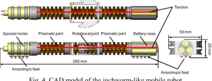
A CAD model of the inchworm-like mobile robot is shown in Fig. 4. The upper and lower images show the top and side views of the robot, respectively. The robot is 50 mm wide, 25 mm tall and 285 mm long in its nominal configuration. The robot is composed of two serially connected prismatic joints to achieve translation, and one rotational joint for planar steering. A tendon, which is attached to a spooler motor, runs centrally through the joints and is fixed to the battery case. Each joint contains at least one solder-based locking mechanism to locally modulate the robot stiffness when the tendon tension is increased by the spooler motor.
Anisotropic feet
Spooler motor Prismatic joint Rotational joint Prismatic joint Battery case
285 mm 50 mm 25 mm Anisotropic feet Tendon
Fig. 4. CAD model of the inchworm-like mobile robot
The spooler motor is based on a Maxon DC motor (see Section IV-C). It can modulate the tendon tension within a range of 0 to 20 N, which is based on the maximum continuous output torque of the motor and gearbox. When the tendon tension is increased, the prismatic and rotational joints deflect, allowing the robot to achieve inchworm-like locomotion. Note that the prismatic and rotational joints possess some natural stiffness due to their structural design, which causes the robot to return to its nominal configuration when the tendon tension is small. By thermally activating the solder-based locking mechanisms, the rotational joint can fix
itself at an arbitrary angle of deflection. Details of these locomotion mechanisms are described in Section III-E.
The robot also has a novel “foot” design, which realizes anisotropic friction coefficients between the foot and ground surface. By employing multiple materials with different friction properties, these feet effectively generate a high friction coefficient for backward motion and a low friction coefficient for forward motion.
B. Prismatic and Rotational Joints
Both the prismatic and rotational joints utilize solder-based locking mechanisms. These mechanisms consist of a thin layer of 60Sn-40Pb solder (188˚C melting temperature), mixed with a low-temperature alloy (Chip Quik, which has a melting temperature of 58˚C [15]) sandwiched between two strips of copper tape. The use of a low-temperature alloy allows the solder melting temperature to be lower (~70˚C) [11], thereby reducing the power requirement for joint activation. Copper was selected because it has excellent wicking compatibility with solder and good thermal conductivity. Each copper tape strip is adhered to an interface that is attached/detached upon solidification/melting of the solder.
The heating element in each locking mechanism is a pair of strain gauges (5.5 x 3 mm2 each) with a total resistance of 120
ohms. These strain gauges are mounted behind the copper tape (i.e. not in contact with the solder-alloy mixture), and are capable of rapidly melting the solder layer (on the order of ten seconds) via resistive heating.
Ongoing studies are being conducted to optimize the solder-alloy mixture by varying parameters such as alloy type and the ratio of solder to alloy. It is important to quantify properties such as melting temperature and yield strength, and to understand the cyclic behavior of the locking mechanisms because the joints are assumed to undergo multiple locking/unlocking cycles.
1) Prismatic Joint
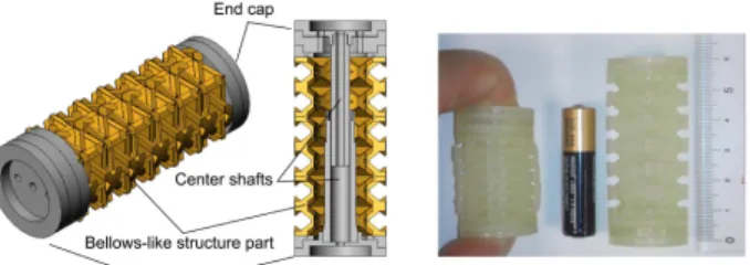
Fig. 5 shows a CAD design and prototype of a soft prismatic joint that utilizes a shear solder-based locking mechanism. The joint consists of a compliant (27 Shore Scale A) structure that was fabricated using 3D printing technologies [16]. The joint has a hollow bellows-like geometry that provides a longitudinal stiffness of 0.23 N/mm. This restoring force is sufficient to propel the robot forward after the compressed joint is allowed to extend (by unlocking the joint and releasing the tendon). As seen in Fig. 6, the joint can contract 18 mm, resulting in a 41% compression ratio. The robot’s two prismatic joints can thus generate 36 mm of translational motion in one contracting/restoring cycle.
A tensile joint was initially used to bond the inner shaft to the lower end cap, but it was difficult to consistently bond the two surfaces if they were not precisely flat and parallel. Therefore, as illustrated in Fig. 6, a shear joint is created at the interface of the center shaft and lower end cap. Copper tape is fixed to the shear joint faces, and the solder-Chip Quik mixture is spread across a portion of the tape. The strain gauge heating element is placed behind the copper tape that is adhered to the end cap.
Fig. 5. Prismatic joint: CAD model (left) and prototype (right)
Fig. 6. Locked and unlocked states of the prismatic joint (left) and integrated solder-based locking mechanism in the prismatic joint (right)
Assuming that the stiffness of the prismatic mechanism is 0.23 N/mm and that the joint compresses a maximum 18 mm, the maximum shear force that each solder joint experiences is 4.17 N. Because the yield shear strength of the solder-Chip Quik composite is unknown, the yield shear strength of 60Sn-40Pb solder is used to estimate the shear strength of the joint. Using (1), and given σs,shear = 39 MPa for 60Sn-40Pb
solder, the shear strength of a 33 mm2 solder joint is 1287 N.
While the cross section of the joint appears to be significantly larger than it needs to be, it has been purposely overdesigned due to the lack of control parameters (e.g. the two bonding surfaces do not necessarily completely overlap each other every time they are brought together).
2) Rotational Joint
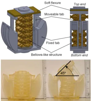
Fig. 7 illustrates a CAD design and prototype of a rotational joint that utilizes shear solder-based locking mechanisms. The joint was designed to rotate through a range of ±45° in a plane, and to maintain a fixed angular position using the solder locking mechanisms. Similar to the prismatic joint, the bending joint utilizes a soft bellows-like structure to provide a restoring force to steer the front of the robot after the compressed joint is allowed to expand on one side (described below). The spooler motor applies, on average, 0.15 N per degree of rotation in the bending joint.
The rotational joint contains a pair of solder locking mechanisms that allows the joint to be locked in either rotational direction. As with the prismatic joint, copper tape and the solder-Chip Quik mixture are employed, with strain gauges acting as heating elements. Each locking mechanism utilizes a pair of fixed tabs (mounted to the bottom end of the joint, see Fig. 7) to constrain the motion of the moveable tab, which is mounted to the top end of the joint. The fixed tabs have an extended surface area covered with copper tape and the solder composite so that the moveable tabs can adhere to them in arbitrary locations, thus allowing the robot to be locked at arbitrary angles. The heating elements, covered with a strip of copper tape with the solder composite, are attached near the end of the moveable tabs.
Fig. 7. Rotational joint CAD model (upper) and prototype (lower)
When the rotational joint is not being used to steer the robot, it remains in its locked state so that the bellows-like structure is compressed longitudinally and both moveable tabs are locked to the fixed tabs (shown in the lower left image in Fig. 7). To steer the robot, one of the two locking mechanisms is unlocked by heating the strain gauges until the solder-alloy mixture exceeds its melting temperature. The top end of the joint, which contains a soft flexure, is then free to deflect under the force of the tendon, with the bellows-like structure applying a restoring force.
Assuming that the stiffness of the rotational joint is 0.15 N/deg and that the joint deflects a maximum 45°, the maximum shear force that the solder joint experiences is 6.7 N. As in the previous analysis with the prismatic joint, the shear strength of a 33 mm2 solder joint is 1287 N. Again, the
joint has been overdesigned due to the lack of control parameters.
Fig. 8. Spooler motor C. Spooler Motor
The spooler motor used for winding/releasing the tendon consists of a Maxon RE10 motor (1.5W, 6V) with a Maxon gearhead GP10A (gear ratio 256:1), a motor cover, and a screw-thread spooler (see Fig. 8). Select specifications of the spooler motor are as follows: maximum tendon winding speed is 25 mm/s, maximum tensile force is 4.5 N, and maximum stroke is 300 mm. The total weight of the spooler motor is 41 g, and the dimensions are 21 mm diameter and 72 mm length.
D. Anisotropic Foot Design
Inchworm-like motion is achieved by compressing and relaxing the prismatic joints. However, a direction-dependent friction coefficient between the robot contact patch and ground is required for the robot to move. Ideally, when the prismatic joints are compressed, the front foot should remain fixed to the ground while the rear foot slides forward. Similarly, while relaxing the joints, the friction of the rear foot should be high relative to the friction of the front foot in order to propel the robot forward.
Fig. 9. ”Finger-nail” foot design, generating anisotropic friction coefficient
To satisfy this requirement, a novel “foot” design has been developed to achieve a relatively large friction coefficient during forward motion and a relatively low friction coefficient during backward motion (see Fig. 9). This “finger nail” design has several discrete structures, each of which is composed of a soft pad made of a low-durometer polymeric material and rigid “nail” made of a hard polymeric material. The nail extends slightly beyond the tip of the pad. Due to their material properties, the pad has a relatively high friction coefficient compared to that of the nail.
Fig. 10. Foot characteristics when resisting forward and backward forces
As shown in Fig. 10-(a), when a force Ff is applied to the
foot in the forward direction, the low friction nail maintains contact with the ground. The pad does not touch the ground since the nail extends slightly beyond the tip of the pad. In this scenario, the foot generates a low friction force Fnail.
When a force Fb is applied to the foot in the backward
direction (see Fig. 10-(b)), the base of the pad deflects, causing the pad to contact the ground. The foot then resists motion with a high friction force Fpad generated by the pad.
Since the nail encompasses the entire front portion of the pad, the anisotropic friction property is achievable even in cases when the force is applied to the foot at an arbitrary angle (see bottom views in Fig. 10).
As shown in Fig. 11, one anisotropic foot is attached to the front of the robot and another is attached at the rear of the robot. When the pad resists motion with a high friction force
Fpad , the forces on the feet should satisfy the following
relationship:
b nail
pad⋅W/2>μ ⋅W/2+F
μ (2)
where μpad and μnail are the friction coefficients of the pad and
the nail, respectively. In general, Fb is the tensile force of the
spooler motor, which is equal to the force required to contract the prismatic joints.
On the other hand, while the robot moves forward:
f nail⋅W/2< F
μ (4)
where Ff is the resultant force of the restoring forces
generated by the prismatic (or rotational) joints.
Note that μnail is the kinetic friction coefficient since the
nail works while slipping with respect to the ground surface, whereas μpad is the static friction coefficient.
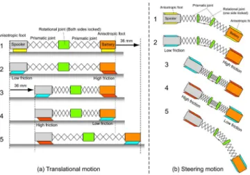
Fig. 11. Locomotion schemes for translational and steering motions E. Inchworm Locomotion Mechanism
The locomotion scheme for translational motion of the robot is illustrated in Fig. 11-(a) and is summarized as follows:
1. The spooler motor retracts the tendon so that the prismatic joints begin to contract;
2. The front anisotropic foot resists motion with a high interfacial friction force, while the rear foot resists motion with a low interfacial friction force;
3. Due to the difference in friction forces at the front and rear feet, the rear part of the robot slides forward; 4. Once the prismatic joint reaches full contraction the
spooler motor releases the tendon. The prismatic joints return to their nominal length due to inherent longitudinal stiffness. The rear anisotropic foot resists motion with a high interfacial friction force, while the front foot resists motion with a low interfacial friction force;
5. Due to the difference in friction forces at the front and rear feet, the front part of the robot slides forward. Repeating the above strategy enables the robot to move forward with an inchworm-like motion.
The locomotion scheme for steering motion is similar to that for translational motion, except that one of the two sides of the rotational joint must be compressed and locked in place while the other side is allowed to expand due to the inherent restoring force of the bellows-like structure. The locomotion mechanism for steering is illustrated in Fig. 11-(b). As explained in Section III-D, during steering the anisotropic feet can generate high friction force during backward motion and low friction force during forward motion.
IV. PROTOTYPE OF INCHWORM-LIKE MOBILE ROBOT AND EXPERIMENTALPERFORMANCE DATA
A. Prototype of Inchworm-like Mobile Robot
A prototype of the inchworm-like mobile robot is shown in Fig. 12. The top-most image shows the robot is in its nominal, fully extended state, while the middle image shows the robot in its fully contracted state. The bottom-most image shows the robot in its mid-steering state via use of the bending joint. Physical properties or the robot are summarized in Table I. The length of the robot is 285 mm in its nominal state. The robot contracts to a length of 230 mm by compressing both prismatic joints (36 mm length) and the rotational joint (19 mm length).
Fig. 12. Prototype of the inchworm-like mobile robot TABLE I
SPECIFICATIONS OF INCHWORM-LIKE MOBILE ROBOT
Nominal Length 285 mm
Minimum Length (full contraction) 230 mm
Maximum Width 50 mm
Maximum Thickness 25 mm
Bending Deflection Angle ± 45 degrees
Power required (motor) 0.3 W
Power required (per heating element) 0.6 W
Weight (w/ dummy battery mass) 145 g
The spooler motor requires 0.3 W to operate the robot at a constant translational speed of 7.5 mm/s. The heating elements of the solder-based locking mechanisms require 0.6 W, but the heating elements are not used while the spooler motor is activated. For this prototype, power was supplied from a DC power supply. The robot was manually operated
by a PC via a microcontroller. Note that commercially available candidates exist for on-board batteries (e.g. the PowerStream GM041225 [17] provides sufficient power for the robot, having 0.3 Wh at only 1.4 g per cell).
In addition, three AAA dry cell batteries are mounted at the front of the robot to serve as proxies for batteries that would be present during untethered operation.
B. Performance Test Results
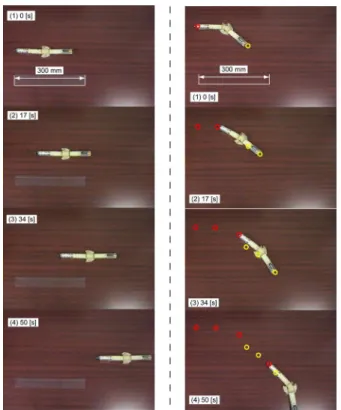
The translational and steering motion characteristics of the inchworm-like robot were studied experimentally. In the experiments, the spooler motor was operated manually via open-loop control. Fig. 13 shows several snapshots of translational and steering motion experiments. The experiments were conducted on a smooth wooden bench top.
Fig. 13. Locomotion performance tests of the robot: Translational motion (Left) and Steering motion (Right)
Operating with the translational locomotion scheme only, it was found that the translational speed of the robot was 7.5 mm/s, or 27 mm per contracting/restoring cycle (without the use of heating elements). This implies that each cycle has a duration of less than 4 seconds. If heating elements were activated, cycle time would increase by 10 seconds for every heating or cooling operation. Theoretically, the advancement in each cycle should be 36 mm since two prismatic joints can contract up to 36 mm. The 9 mm reduction in distance traveled per cycled is due to slippage between the anisotropic feet and the ground. This slippage causes the robot to lose net translational displacement in the contracting/restoring cycle. The steering speed of the robot was measured to be approximately 0.9 deg/s.
V. CONCLUSION
This paper presented an inchworm-like soft robotic system that can achieve locomotion on flat smooth surfaces. Novel concepts for realizing soft robotics that were explored include: 1) minimizing the number of traditional actuators to maximize the overall “softness” of the system, and 2) utilizing active TR fluids to locally control the robot’s global response to external loading. Specifically, the robot achieved inchworm-like translational and steering motion using 1) a central tendon-spooler motor actuator, and 2) thermally activated joints that utilize solder-based locking mechanisms. In addition, “feet” with direction-dependent friction properties were designed to allow locomotion.
REFERENCES
[1] M. Hakozaki, H. Oasa, and H. Shinoda, "Telemetric Robot Skin," Proc. of the IEEE International Conf. on Robotics and Automation (ICRA), Detroit, MI, 1999.
[2] G. Hirzinger, N. Sporer, A. Albu-Schaffer, M. Hahnle, R. Krenn, A. Pascucci, and M. Schedl, "DLR's Torque-controlled Light Weight Robot III," Proc. of the IEEE Robotics and Automation Conf., Washington, D.C., 2002.
[3] D. Sasaki, T. Noritsugu, and M. Takaiwa, "Development of Active Support Splint driven by Pneumatic Soft Actuator (ASSIST)," Proc. of the IEEE International Conf. on Robotics and Automation (ICRA), Barcelona, Spain, 2005.
[4] Y. Sugiyama and S. Hirai, "Crawling and Jumping of Deformable Soft Robot," Proc. of the IEEE/RSJ International Conf. on Intelligent Robots and Systems (IROS), Sendai, Japan, 2004.
[5] I. Hunter and S. Lafontaine, "A Comparison of Muscle with Artificial Actuators," 5th Technical Digest., IEEE. pp. 178-185, 1992.
[6] M. D. Grissom, V. Chitrakaran, D. Dienno, M. Csencits, M. Pritts, B. Jones, W. McMahan, D. Dawson, C. Rahn, I. Walker, "Design and experimental testing of the OctArm soft robot manipulator," Proc. of SPIE Conf., Orlando, FL, 2006.
[7] A. Crespi, A. Badertscher, A. Guignard, and A. Ijspeert, "AmphiBot I: An amphibious snake-like robot," Robotics and Autonomous Systems, vol. 50, No. 4, pp. 163-175, 2005.
[8] B. Trimmer, A. Takesian, B. Sweet, C. Rogers, D. Hake, and D. Rogers, “Caterpillar locomotion: A new model for soft-bodied climbing and burrowing robots,” 7th International Symposium on Technology and the Mine Problem, Monterey, CA, 2006.
[9] M. Minor, H. Dulimarta, G. Danghi, R. Mukherjee, R. Lal Tummala, and D. Aslam, “Design, Implementation, and Evaluation of an Under-actuated Miniature Biped Climbing Robot,” Proc. of the IEEE/RSJ International Conf. on Intelligent Robots and Systems (IROS), Takamatsu, Japan, 2000.
[10] N. Cheng, Design and Analysis of Active Fluid-and-Cellular Solid Composites for Controllable Stiffness Robotic Elements, MS Thesis, Massachusetts Institute of Technology, 2009.
[11] M. Telleria, M. Hansen, D. Campbell, A. Servi, and M. Culpepper, “Modeling and Implementation of Solder-activated Joints for Single-Actuator, Centimeter-Scale Robotic Mechanisms,” IEEE International Conf. on Robotics and Automation (ICRA), Anchorage, AK, 2010.
[12] H. Manko, Solders and Soldering, McGraw-Hill, 1979.
[13] S. Nightingale and O. Hudson, Tin Solders, British Nonferrous Met. Res. Assoc. Res. Manogr. 1, 1942.
[14] G. Humpston and D. Jacobson, Principles of Soldering, ASM International, pp. 175-177, 2004.
[15] Chip Quik [Online]. Available: http://www.chipquikinc.com/ [16] Connex500™ Multi-Material 3D Printing System [Online]. Available:
http://www.objet.com/3D-Printer/Connex500/
[17] Lithium Polymer Batteries from PowerStream [Online]. Available: http://www.powerstream.com/li-pol.htm