HAL Id: hal-02149002
https://hal.archives-ouvertes.fr/hal-02149002
Submitted on 6 Jun 2019
HAL is a multi-disciplinary open access
archive for the deposit and dissemination of
sci-entific research documents, whether they are
pub-lished or not. The documents may come from
teaching and research institutions in France or
abroad, or from public or private research centers.
L’archive ouverte pluridisciplinaire HAL, est
destinée au dépôt et à la diffusion de documents
scientifiques de niveau recherche, publiés ou non,
émanant des établissements d’enseignement et de
recherche français ou étrangers, des laboratoires
publics ou privés.
Site U1450
Christian France-Lanord, Volkhard Spiess, Adam Klaus, R.R. Adhikari, S.K.
Adhikari, J.-J. Bahk, A. Baxter, J.W. Cruz, S.K. Das, P. Dekens, et al.
To cite this version:
Christian France-Lanord, Volkhard Spiess, Adam Klaus, R.R. Adhikari, S.K. Adhikari, et
al..
Site U1450.
Proceedings of the International Ocean Discovery Program,
2016,
doi:10.14379/iodp.proc.354.104.2016
Site U1450
1C. France-Lanord, V. Spiess, A. Klaus, R.R. Adhikari, S.K. Adhikari, J.-J. Bahk, A.T. Baxter, J.W. Cruz, S.K. Das, P. Dekens, W. Duleba, L.R. Fox, A. Galy, V. Galy, J. Ge, J.D. Gleason, B.R. Gyawali, P. Huyghe, G. Jia, H. Lantzsch, M.C. Manoj, Y. Martos Martin, L. Meynadier, Y.M.R. Najman, A. Nakajima, C. Ponton, B.T. Reilly, K.G. Rogers, J.F. Savian, T. Schwenk, P.A. Selkin, M.E. Weber, T. Williams, and K. Yoshida2
Keywords: International Ocean Discovery Program, IODP, Expedition 354, JOIDES Resolution, Site U1450, Bengal Fan
1France-Lanord, C., Spiess, V., Klaus, A., Adhikari, R.R., Adhikari, S.K., Bahk, J.-J., Baxter, A.T., Cruz, J.W., Das, S.K., Dekens, P., Duleba, W., Fox, L.R., Galy, A., Galy, V., Ge, J., Gleason, J.D.,
Gyawali, B.R., Huyghe, P., Jia, G., Lantzsch, H., Manoj, M.C., Martos Martin, Y., Meynadier, L., Najman, Y.M.R., Nakajima, A., Ponton, C., Reilly, B.T., Rogers, K.G., Savian, J.F., Schwenk, T., Selkin, P.A., Weber, M.E., Williams, T., and Yoshida, K., 2016. Site U1450. In France-Lanord, C., Spiess, V., Klaus, A., Schwenk, T., and the Expedition 354 Scientists, Bengal Fan.
Proceed-Contents
1 Site summary
3 Background and objectives
6 Operations
10 Lithostratigraphy
25 Biostratigraphy
26 Paleomagnetism
30 Geochemistry and microbiology
33 Physical properties
38 Downhole measurements
40 Stratigraphic synthesis
45 References
Site summary
Site U1450 (proposed Site MBF-2A) occupies a central position at 8°0.42′N and 87°40.25′E in the east–west transect across the Ben-gal Fan at 8°N. It is located at equal distance from Site U1451 on the flank of the Ninetyeast Ridge and Site U1455 on the flank of the 85°E Ridge. The overall thickness of the fan reaches ~4 km at this location (Curray et al., 2003). Neogene sediment thickness de-creases toward the two ridges, which is likely the result of ongoing deformation on both ridges during the Neogene (Schwenk and Spiess, 2009). At this central position of the transect, the upper Miocene and Pliocene–Pleistocene sections of the fan appear to be most expanded and are inferred to contain a higher resolution re-cord, as well as accumulating, on average, coarser grained material. The shallow section at this site is one of the seven ~200 m deep sec-tions along the 8°N transect that constrain the Middle Bengal Fan architecture in space, time, and sediment delivery rate during the Pleistocene. The deeper section at this site will document the deliv-ery mechanisms of the fan and the climatically and tectonically in-fluenced sediment supply from the Himalaya during the Neogene. Changes in the source regions in response to tectonic and climatic evolution of the Himalaya are expected to be reflected in the sedi-ment’s mineralogical and geochemical compositions, the geochro-nological data, and in accumulation rates across the transect.
Principal results
Half-length advanced piston corer (HLAPC) coring combined with 4.8 m advances by drilling without coring was essential to achieve sufficient recovery in difficult lithologies with reasonable drilling times to reach 812 meters below seafloor (mbsf ). This ap-proach proved to be particularly efficient in recovering loose sand that otherwise would have been washed out during rotary core bar-rel (RCB) or extended core barbar-rel (XCB) coring. Because of
remark-ably low lithification of the sediment formation, this HLAPC approach permitted piston coring to 550 mbsf, and seven HLAPC cores were taken in even deeper intervals to a maximum depth of 688 mbsf.
As at other transect sites, the sedimentary succession is domi-nated by turbidites of siliciclastic composition with detrital carbon-ate contents between 5% and 10%. These turbidites have high accumulation rates (~5–10 cm/ky) from the upper Miocene to lower Pliocene. From the Pliocene to Pleistocene, turbidite accumu-lation peaks around 20–25 cm/ky. These turbidites have close min-eralogical and geochemical affinities with sand and silt sampled in the Ganges, Brahmaputra, and lower Meghna Rivers. They carry all the mineral characteristics and major element composition charac-teristics of river sediments derived from high-grade metamorphic rocks of the Himalayan range. Sand comprises ~40% of the section cored at Site U1450; this composition is similar to the grain size spectrum expected from river-derived detrital material, so bias due to turbiditic transport may be minor. Downhole logging was not possible at this site because of poor hole conditions, so it remains difficult to estimate the exact proportion of sand, silt, and clay. Overall, the mineralogical and chemical composition of the turbid-ites appears almost uniform, but detrital carbonate content tends to be gradually higher in sediment older than the Pliocene, reaching concentrations twice as high as in modern rivers and Pleistocene turbidites. This evolution suggests a change in eroded lithologies (i.e., a higher proportion of Tethyan formations exposed to erosion during the Miocene) and/or a change in weathering conditions.
Another distinctive, more carbonate-rich lithology is repre-sented by about 10 relatively thin hemipelagic intervals composed of calcareous clays. These intervals correspond to periods of slow accumulation at the site when pelagic deposition is significant enough to be identified but is still diluted in variable proportions by a clay component. This clay is assumed to be related to the plumes
Proceedings of the International Ocean Discovery Program Volume 354
generated by surrounding turbidity currents that originate from canyons and the slope offshore Bangladesh. However, this affinity remains to be determined by geochemical and clay mineralogical approaches. These low-accumulation intervals will provide geo-chronological control through a combination of paleomagnetic and biostratigraphic ground-truth data and orbital tuning, which will be essential for constraining detailed accumulation rates. Testing their continuity across the transect will be a key element for the inte-grated study of fan construction dynamics and long-term detrital sedimentary input utilizing seismic correlation across the transect.
Site U1450 represents a reference section for shore-based stud-ies of the erosion of the Himalaya during the Neogene. The detrital sediments cored here present little evidence of a change over the last 8 My, suggesting rather steady conditions of erosion in the Hi-malayan basin. Such a change would require a major mountain range undergoing fast erosion and a monsoonal climate that allows rapid transport to inhibit weathering of the sediment in the flood-plain. Unlike in the distal fan cored during Leg 116 (Cochran, Stow, et al., 1989), Site U1450 sediments show no clear change in accumu-lation rate, grain size, and clay mineralogy. This stability suggests that the smectite-rich fine turbidites recorded in the distal fan from 7 to 1 Ma (Bouquillon et al., 1990) may relate more to a change in the channel and turbidity current routing to the distal fan than to a change in Himalayan erosion. Site U1450 also covers the interval of expansion of C4 photosynthetic flora (i.e., savanna at the expense of forest) recorded in both the continental basin and distal and middle fan (Galy et al., 2010). Sediments recovered at Site U1450 will allow detailed studies of this ecological transition and its possible connec-tion with climate changes or erosion condiconnec-tions.
Operations
Site U1450 consists of two holes. Hole U1450A was cored to 687.4 m drilling depth below seafloor (DSF) using primarily the HLAPC system alternating with short (4.8 m) advances without coring. The advanced piston corer (APC) and XCB systems were used in the shallow and deepest portions of the hole, respectively. Because of very low recovery at depth with the XCB system, we pulled out and planned for deeper penetration coring and logging in a second hole later in the expedition. Overall, 282.7 m of core was recovered for the 444.7 m cored in Hole U1450A. Hole U1450B was drilled without coring to 608.0 m DSF and then RCB cored continu-ously to 811.9 m DSF. Coring in Holes U1450A and U1450B over-laps from 608.0 to 677.8 m DSF. This deeper section cored 203.9 m and recovered 46.7 m of sediment (23%). Downhole logging was at-tempted with the triple combo tool string. On the way down, the bottom of the tool string encountered an obstruction at 133.7 m DSF and was stuck, likely in a collapsing sand layer. After the tool string was released, a short section of logging data was acquired, and deep logging of the site was abandoned.
Lithostratigraphy
Recovered sediments from Site U1450 are divided into 24 litho-stratigraphic units based on lithologic and paleontological charac-teristics obtained through macroscopic and smear slide analyses and on physical property measurements.
The overall dominant lithology for Site U1450 (84% of total re-covered material) is siliciclastic and comprises fining-upward se-quences of fine sand, silt, and clay (i.e., turbidites), as well as homogenized sands and mixed silt-clay layers. These turbidites carry major and trace mineral characteristics of Himalayan rivers
and of high-grade metamorphic rocks of the Himalaya. Clay assem-blages are dominated by illite, which is indicative of the same rivers. Siliciclastic units alternate with at least 10 units of calcareous clay (16% of total recovered material). The thickest continuous calcare-ous clay intervals are in lithostratigraphic Unit III and consist of 5.14 m in Core 354-U1450A-34F and 4.8 m in Core 36F. Sediments give way downhole in Hole U1450B to increasingly more lithified material (e.g., limestone and claystone) from 627.50 m core depth below seafloor (CSF-A) to the base of recovered material. Addition-ally, Site U1450 contains three volcanic ash layers.
Lithologic differences between units and variations in grain size and bed thickness reflect cycles of turbidity current activity and channel abandonment. Sand intervals may represent interlevee sheet flows, whereas finer grained fractions are more likely pre-served in levee deposits. Bioturbated calcareous clays represent times of local channel inactivity with reduced and finer siliciclastic deposition that reflects a relative increase in the contribution of bio-genic origin from the pelagic zone. Many intervals of calcareous clay show repeated sequences of color-graded beds, which can be attributed to increased entrainment of siliciclastic material, changes in water column productivity, or changes in the oxidation/reduction horizons of pore water. In Hole U1450B, intervals dominated by cal-careous and/or clayey material become increasingly lithified with depth, and many are intercalated with very thin to thin silt or silt-stone layers. Plant fragments occur throughout the cored section, more commonly in silt and siltstone intervals, although a few sand-dominated units also contain macroscopic organic material. At the top of Hole U1450A, an 18 cm thick ash layer presumably corre-sponds to the ~75 ka Toba volcanic eruption that produced wide-spread tephra deposits across the Bay of Bengal (e.g., Gasparotto et al., 2000).
Biostratigraphy
Calcareous nannofossil and planktonic foraminiferal biostrati-graphic analyses conducted on Site U1450 samples identified 18 biomarker events. These events were used to construct 4 foraminif-eral and 11 nannofossil biozones, providing excellent age control ex-tending back to the late Miocene. The recovery of a late Miocene succession achieves one of the key objectives of this expedition and includes sediments that may contain the C4 photosynthetic flora expansion (Galy et al., 2010).
The succession of biostratigraphic zones at this site appears continuous, as no significant nannofossil biostratigraphic hiatuses were observed, indicating that the fan has been accumulating sedi-ments, albeit at highly variable accumulation rates, since the late Miocene.
Paleomagnetism
A preliminary paleomagnetic study was conducted on 36 of the 86 cores collected from Hole U1450A, comprising 108 archive sec-tion-half and 52 discrete sample measurements. Sandy and/or de-formed intervals were not measured. Polarity zones corresponding to the Jaramillo and Cobb Mountain Subchrons were identified in a calcareous clay unit in Core 36F (173.30–174.60 and 175.70–175.90 m CSF-A, respectively). An additional pair of reversals was ob-served in Core 52F (248.38 and 248.51 m CSF-A), but the polarity chron to which they belong has not yet been identified. The thick-ness of the Jaramillo and Cobb Mountain polarity zones in Hole U1450A suggests an accumulation rate for the calcareous clay inter-val similar to that in Hole U1449A (~1.5 cm/ky).
Physical properties
Physical property data acquired on Site U1450 cores includes density, magnetic susceptibility, P-wave velocity, natural gamma ra-diation (NGR), and thermal conductivity. The data are mostly of good quality, but the results from disturbed and partially filled sec-tions are less reliable, as described below.
Physical properties at Site U1450 primarily reflect lithologic variations, with downcore compaction having a relatively minor ef-fect. Using the principal lithologic name from the core description, which assigned six types of lithologies, we calculated the total thick-ness and average physical property value for each lithology. From the 319 m total core recovery assigned to lithology (39.6%), sand ac-counts for 131 m (41%), silt for 46 m (14%), clay for 72 m (22%), cal-careous clay for 45 m (14%), claystone for 13 m (4%), calcal-careous claystone for 6 m (2%), and limestone for 7 m, with additional thin ash layers. In general, sands and silts have the highest density and P-wave velocity, sands have the highest magnetic susceptibility, clays have the highest NGR, and calcareous clay has the lowest values in all measurements. Some sand-rich intervals were difficult to re-cover and were often fluidized, which sometimes resulted in incom-pletely filled core liners; these cores had the effect of giving unexpectedly low gamma ray density, magnetic susceptibility, and NGR values. Cores that had inflow of core material (“suck in”) also likely have lower than expected values in these physical properties Because of volume reduction.
Geochemistry
Detailed pore water measurements distinguish four hydrologic units based on sulfate, phosphate, silica, magnesium, potassium, calcium, and alkalinity contents. Carbonate contents of bulk sedi-ments vary widely from 1.2 to 63.2 wt% CaCO3, reflecting contrast-ing depositional environments and significant contributions from detrital carbonates. The carbonate contents of turbiditic sediments, however, exhibit a significant change at ~620 m CSF-A, where they roughly double from an average of 3.8 wt% above to 7.3 wt% below. This transition occurs around the Miocene/Pliocene boundary and most likely reflects a change in detrital carbonate supply. A similar change was also observed at Site U1451 and can be deduced from Deep Sea Drilling Project (DSDP) Site 218 total inorganic carbon (TIC) data (von der Borch, Sclater, et al., 1974). Overall, total or-ganic carbon (TOC) contents are low, with an average value of 0.4 wt%. Within turbidites, TOC broadly covaries with Al/Si ratios—a proxy for sediment grain size and mineral composition—reflecting preferential association of organic matter with clays previously doc-umented in both the modern Ganga-Brahmaputra river system and in active channel-levee sediments in the Bay of Bengal deposited over the past 18 ky (e.g., Galy et al., 2007). The TOC budget is likely also affected by the frequent presence of woody debris concentrated in the lower part of many turbiditic sequences. In turbiditic sedi-ments, major element composition (e.g., Fe/Si and Al/Si) closely matches the chemical composition observed in sediments from the modern Ganga-Brahmaputra river system for both the trend and the range of variation (e.g., Galy and France-Lanord, 2001). At the low end of Al/Si ratios, the lack of significant difference suggests that extreme sorting documented in coarse bed sediments from these rivers is also generated by turbidity current at Site U1450. Conversely, the clay-rich end-member recovered at Site U1450 is only slightly more aluminous (and likely finer) than monsoonal sur-face-suspended sediments from the lower Meghna River.
Microbiological subsampling of sediments and pore water at Site U1450 included establishing a microbial cell counting method,
with further processing of the samples to be performed following the expedition.
Downhole measurements
Five downhole measurements were taken in Hole U1450A with the advanced piston corer temperature tool (APCT-3), ranging from 4.6°C at 86.3 m DSF to 13.5°C at 318.1 m DSF. These measure-ments return a geothermal gradient of 38°C/km, which appears to be in the expected range.
Stratigraphic summary
Lithologic and physical property results confirm the expectation that Site U1450 would contain a high proportion of sand in the re-covered cores; it may be even higher in the formation. As at Site U1449, the match between these data sets and seismic facies and re-flectors will allow us to assign broad lithologic categories to the seis-mic units and thus extrapolate throughout the seisseis-mic data set and between Expedition 354 drill sites. These data also allow identifica-tion of major deposiidentifica-tional processes, which can be integrated to re-construct the stacking pattern and evolution of fan deposition.
Because Site U1450 reaches back to 8 Ma at 812 m DSF, a pre-cise seismic stratigraphy will be established postexpedition, based on major hemipelagic units and associated distinct seismic reflec-tors. These units and reflectors will be used to estimate accumula-tion for various subfan units in time slices on the order of several hundred thousand to millions of years, one of the main expedition objectives. Site U1450 is located in a key position between the two other deep penetration sites (U1451 and U1455).
Recovering material of sufficient quality was a challenge during Expedition 354 and particularly at Site U1450 because of the high proportion of sand. It was unexpected that the consolidation state of sand apparently does not change much with depth. Although loose sand was recovered with the APC and HLAPC systems to fusal depth (560 and 630 m DSF in Holes U1450A and U1450B, re-spectively), the XCB and RCB systems provided little or no recovery of sand. The sand proportion is likely underrepresented in cores from the deeper section of the site. Based on discrete sample mea-surements of density and porosity, a downhole trend of porosity loss is observed, but from lithologic observations we infer that consoli-dation state is different for different grain sizes. Clay shows a grad-ual transition to claystone with depth, with increasing P-wave velocities and densities downhole. However, sand was not recovered in any more consolidated state within the entire 800 m cored sec-tion.
Based on biostratigraphic and paleomagnetic data, the upper Miocene to lower Pliocene portion of the site is characterized by a relatively uniform accumulation, averaging about 5–10 cm/ky. From the early Pliocene to the Pleistocene, fan accumulation has intensi-fied (~20–25 cm/ky), accompanied by a transition from more silt-dominated to sand-silt-dominated lithologies. As at Sites U1449 and U1451, turbidite deposition ceased at this site at ~300 ka, as ob-served at 11°N in the axial fan (Weber et al., 2003).
Background and objectives
Site U1450 occupies a central position at 8°0.42′N, 87°40.25′E in the east–west transect across the Bengal Fan at 8°N (see Figures F3, F4, and F8 in the Expedition 354 summary chapter [France-Lanord et al., 2016d]). It is located at equal distance from Site U1451 on the flanks of the Ninetyeast Ridge and Site U1455 above the 85°E Ridge. The overall thickness of the fan reaches ~4 km at this location
(Cur-ray et al., 2003). Neogene sediment thickness decreases toward the two ridges, likely the result of ongoing deformation on both ridges during the Neogene (Schwenk and Spiess, 2009). Site U1450 is lo-cated in the center of the transect where the upper Miocene and Pliocene–Pleistocene sections of the fan appear to be most ex-panded and were inferred to contain a higher resolution record and accumulate, on average, coarser grained material. It was also in-ferred, however, that the fan has maintained a flat average topogra-phy and therefore channel and depocenter migration were not directly affected by any tectonic activity.
The shallow section at this site is one of the seven ~200 m thick sections of the 8°N transect at which we investigated Middle Bengal Fan architecture in space and time to reconstruct Pleistocene sedi-ment delivery rates in conjunction with depocenter migration. This site also allows insight into the delivery mechanisms of the fan and the climatically and tectonically influenced sediment supply from the Himalaya during the Neogene. Because the site provides a long-term record of turbiditic deposition since the late Miocene, these sediments can be analyzed for detrital particles predominantly sup-plied by the Ganga-Brahmaputra river system, as shown by earlier fan studies (e.g., France-Lanord et al., 1993). Changes in the source regions in response to tectonic processes and climatic conditions in the Himalayan basin were expected to be reflected in the sediment composition and mineralogy as a result of Himalayan erosion. In this context, it is of particular interest to resolve in detail the emer-gence of the C4 photosynthetic flora in the Gangetic plain that is clearly documented in Bengal fan sediments (e.g., France-Lanord and Derry, 1994; Freeman and Colarusso, 2001).
The deeper portion of Site U1450 will be compared with the two other deep-penetration transect sites: Site U1451 above the Ninet-yeast Ridge and Site U1455 above the 85°E Ridge.
The seafloor in the vicinity of Site U1450 is relatively flat and
smooth (Figure F1). However, there is an abandoned meandering
channel ~10 km east of the site.
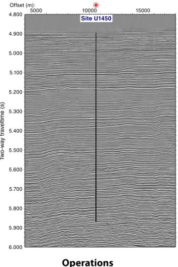
Figure F2 shows the shallow portion of the seismic data in the vicinity of Site U1450. A thin sedimentary unit of uniform thickness covers the area. Beneath this unit, in the upper 200 ms two-way traveltime (TWT), several smaller channel-levee structures can be identified within <10 km of the site, interrupted by reflectors of pro-nounced continuity. Deeper than 200 ms TWT, reflections are nearly parallel and sediment packages mostly uniform in thickness. This interval is comparable to depositional style and units observed at the other transect sites.
Deeper than 5.15 s TWT (Figure F3), smaller scale channels are recognized, and associated levee systems cause both converging re-flections within these units and onlapping rere-flections of overlying interlevee sediments or younger levees. Overall, reflectivity and re-flector geometries remain similar throughout the entire section be-low 5.15 s TWT. Deeper than 5.7 s TWT, channel-levee structures are absent. Drilling at this and the two other deep-penetration sites should elucidate the causes for the absence of channel construction before the late Miocene. In particular, it should determine whether there is a relationship between the nature and quantity of delivered material or changes in the erosional regime or the transport system from the delivering rivers through the fan.
Figure F1. Bathymetric and track chart, Site U1450. Projection is UTM Zone 45N. Multibeam bathymetry was acquired during R/V Sonne Cruises SO125 and SO188. Blue line = seismic Line SO125-GeoB97-027 with common depth point annotation. Contour interval is 20 m. Portions of seismic data in the vicinity are shown in Figures F2 (red line; 22 km) and F3 (14 km).
N 3500 3540 3580 3620 3660 3700 3740 3780 3820 8 0 0 0 9 0 0 0 1 0 0 0 0 1 1 0 0 0 1 2 0 0 0 1 3 0 0 0 1 4 0 0 0 1 5 0 0 0 0 370 8°15' N 8°0' 7°45' 87°15'E 87°30' 87°45' 88°0' 530000 540000 550000 560000 570000 580000 590000 600000 610000 X/Y: Meters 855000 865000 875000 885000 895000 905000
Site U1452 Site U1450
(m)
25000
0 5000 10000 15000 20000
W
Figure F2. Seismic Line SO125-GeoB97-027 across Site U1450, showing upper portion of sedimentary section. 0 Offset (m): 4.850 4.900 4.950 5.000 5.050 5.100 5.150 5.200 5.250 Site U1450 T w o-w a y tr a v eltime (s) 5000 10000 15000 20000
Operations
Site U1450 consists of two holes. Hole U1450A was cored to 687.4 m DSF using primarily the HLAPC system alternating with short (4.8 m) advances without coring. The APC and XCB systems were only used in the shallow and deepest portions of the hole, re-spectively. Hole U1450B was drilled without coring to 608.0 m DSF and RCB cored continuously from there to 811.9 DSF, and then downhole logging was attempted.
Hole U1450A
After the short 26 nmi transit from Site U1449, we arrived at Site U1450 at 1830 h on 10 February 2015 and lowered the bit to the seafloor. We spudded Hole U1450A at 0255 h on 11 February, and the mudline core established the seafloor at 3655.3 meters below sea level (mbsl). This hole was drilled to a total depth of 687.4 DSF using a combination of coring (APC, HLAPC, and XCB systems) and short (mostly 4.8 m) advances without coring. Nonmagnetic core barrels were used for all APC and HLAPC cores, and the non-magnetic drill collar was in the bottom-hole assembly (BHA). All cores, penetration depths, core recovery, and time recovered on deck are presented in Table T1.
We used the APC system for the first three cores (1H–3H, 0– 20.2 m DSF; 20.2 m cored; 18.63 m recovered). Because the latter two cores were partial strokes, we switched to the HLAPC system.
Cores 4F–8F extended from 20.2 to 43.7 m DSF with a range of coveries (0%–72%); despite this change we did not advance by re-covery but rather the full 4.7 m barrel length each core.
From 43.7 to 132.9 m DSF (below Core 8F through Core 27F), we took a series of HLAPC cores interspersed with six 4.8 m long advances without coring. These HLAPC cores were taken consecu-tively when fine-grained intervals (e.g., without sand/silt) were en-countered. Two cores with the APC system (Cores 22H and 24H) were taken in this section, but they recovered only 3.35 m of sedi-ment. These were the only two cores where core orientation was at-tempted.
Based on our experiences in the upper portion of this hole and at Site U1449, we decided to deepen the hole by an alternating series of 4.7 m long HLAPC cores followed by 4.8 m advances without coring. The full APC coring system could not sufficiently pene-trate/recover this formation, and the XCB system, although it could penetrate it, could not recover core from this type of formation. In addition, the science objectives required deep penetration sampling at multiple sites, which could not be accomplished in time if the HLAPC was used continuously. This alternating pattern penetrated 428.4 m of formation from 132.9 to 561.3 m DSF (Cores 28F–119F). The only exception to this pattern occurred in a few intervals where HLAPC cores were taken consecutively (Cores 80F–84F, 114F, 115F, and 117F–119F). The HLAPC cores taken from this interval (Cores 28F–119F) penetrated 226.8 m of formation and recovered 176.7 m of core (77%). Forty-two 4.8 m advances without coring penetrated 201.6 m of formation.
Because we had some difficulty getting Core 119F to penetrate the formation, we cored the rest of the hole with the XCB system, except for five HLAPC cores and three 4.8 m advances without cor-ing. Cores 120X–123X cored 37.7 m (561.3–599.0 mbsf ) and recov-ered 8.89 m (24%). Because the penetration rate substantially increased while cutting the last part of Core 123X, we inferred that the formation had likely changed back to sand. We switched back to HLAPC coring, as it was the most likely system to be able to recover sand. We then cored an alternating series of HLAPC cores (124F, 126F, and 128F) and 4.8 m advances without coring that penetrated 11.2 m of formation and recovered 8.89 m (85%).
The lowermost section of the hole consisted of mostly of XCB cores, with two HLAPC cores. Cores 129X and 132X–136X (619.8– 628.2 and 637.7–686.3 mbsf ) penetrated 57.0 m and recovered 6.47 m of core (11%). Two HLAPC cores (130F and 137F; 628.2–632.9 and 686.3–687.4 mbsf ) penetrated 5.8 m and recovered 4.05 m (70%). The deepest core in this hole (HLAPC Core 137F) set the re-cord for the deepest penetration piston core in scientific ocean drill-ing.
We decided to terminate operations in Hole U1450A after this last HLAPC core. We felt that recovering core to the 900 mbsf tar-get objective and obtaining good wireline logs would be better achieved by drilling a new RCB hole at this site later in the expedi-tion. We pulled the drill string out of Hole U1450A, and the bit cleared the seafloor at 2035 h on 16 February and was back on the rig floor at 0235 h the next day. After the drill floor was secured and the thrusters raised, we started the transit to Site U1451 at 0418 h on 17 February. We decided we would return to core the deeper portion of Site U1450 later in the expedition.
Five APCT-3 formation temperature measurements were con-ducted in Hole U1450A at 86.3, 118.7, 156.6, 175.6, and 318.1 m DSF (while taking Cores 17F, 24H, 32F, 36F, and 66F, respectively). The last of these measurements is the deepest (318.1 m DSF) APC formation temperature measurement ever obtained.
Figure F3. Seismic Line SO125-GeoB97-027 across Site U1450, showing com-plete sedimentary section cored. A 0.5 s AGC algorithm was applied to equalize amplitudes throughout the seismic section. Total depth = 811 m DSF. Site U1450 5000 10000 15000 4.800 4.900 5.000 5.100 5.200 5.300 5.400 5.500 5.600 5.700 5.800 5.900 6.000 Offset (m): T w o-w a y tr a v eltime (s)
Table T1. Site U1450 core summary. * = cores when sepiolite mud was circulated. DRF = drilling depth below rig floor, mbsl = meters below sea level, DSF = drill-ing depth below seafloor. H = advanced piston corer, F = half-length APC, X = extended core barrel. (Continued on next two pages.) Download table in .csv for-mat.
Hole U1450A Hole U1450B
Latitude: 8°0.4201′N Latitude: 8°0.4192′N Longitude: 87°40.2478′E Longitude: 87°40.2586′E Time on hole (days): 6.4 (153.8 h) Time on hole (days): 4.0 (96.25 h)
Seafloor (drill pipe measurement below rig floor, m DRF): 3666.0 Seafloor (drill pipe measurement below rig floor, m DRF): 3666.3 Distance between rig floor and sea level (m): 10.7 Distance between rig floor and sea level (m): 10.9
Water depth (drill pipe measurement from sea level, mbsl): 3655.3 Water depth (drill pipe measurement from sea level, mbsl): 3655.4 Total penetration (drilling depth below seafloor, m DSF): 687.4 Total penetration (drilling depth below seafloor, m DSF): 811.9 Total depth (drill pipe measurement from rig floor, m DRF): 4353.4 Total depth (drill pipe measurement from rig floor, m DRF): 4478.2 Total length of cored section (m): 444.7 Total length of cored section (m): 203.9
Total core recovered (m): 282.73 Total core recovered (m): 46.66 Core recovery (%): 64 Core recovery (%): 23 Drilled interval (m): 242.7 Drilled interval (m): 608 Total number of cores: 86 Total number of cores: 21
Core Top of cored inter-val DSF (m) Bottom of cored inter-val DSF (m) Interval cored (m) Interval ad-vanced with-out coring (m) Core recovered length (m) Curated length (m) Recovery (%) Date on deck (mm/dd/yy), time on deck UTC (h) Date on deck (mm/dd/yy), time on deck UTC + 6 (h) (ship local time)
354-U1450A-1H 0.0 8.5 8.5 8.52 8.52 100 02/10/15 2135 02/11/15 0335 2H 8.5 11.7 3.2 3.18 3.18 99 02/10/15 2255 02/11/15 0455 3H 11.7 20.2 8.5 6.93 6.93 82 02/11/15 0040 02/11/15 0640 4F 20.2 24.9 4.7 3.37 3.37 72 02/11/15 0215 02/11/15 0815 5F 24.9 29.6 4.7 0.00 0.00 0 02/11/15 0335 02/11/15 0935 6F 29.6 34.3 4.7 1.37 1.37 29 02/11/15 0640 02/11/15 1240 7F 34.3 39.0 4.7 1.87 1.87 40 02/11/15 0750 02/11/15 1350 8F 39.0 43.7 4.7 2.20 2.20 47 02/11/15 0900 02/11/15 1500 91 43.7 48.5 4.8 *****Drilled interval***** 02/11/15 0920 02/11/15 1520 10F 48.5 53.2 4.7 3.75 3.75 80 02/11/15 1005 02/11/15 1605 11F 53.2 57.9 4.7 3.65 3.65 78 02/11/15 1120 02/11/15 1720 12F 57.9 62.6 4.7 3.68 3.68 78 02/11/15 1225 02/11/15 1825 131 62.6 67.4 4.8 *****Drilled interval***** 02/11/15 1255 02/11/15 1855 14F 67.4 72.1 4.7 5.01 5.01 107 02/11/15 1340 02/11/15 1940 151 72.1 76.9 4.8 *****Drilled interval***** 02/11/15 1400 02/11/15 2000 16F 76.9 81.6 4.7 4.50 4.50 96 02/11/15 1520 02/11/15 2120 17F 81.6 86.3 4.7 5.02 5.02 107 02/11/15 1700 02/11/15 2300 18F 86.3 91.0 4.7 4.78 4.78 102 02/11/15 1900 02/12/15 0100 191 91.0 95.8 4.8 *****Drilled interval***** 02/11/15 1930 02/12/15 0130 20F 95.8 99.8 4.0 3.94 3.94 99 02/11/15 2040 02/12/15 0240 21F 99.8 104.5 4.7 4.91 4.91 104 02/11/15 2215 02/12/15 0415 22H 104.5 106.5 2.0 2.64 2.64 132 02/11/15 2355 02/12/15 0555 231 106.5 109.2 2.7 *****Drilled interval***** 02/12/15 0020 02/12/15 0620 24H 109.2 118.7 9.5 0.71 0.71 7 02/12/15 0140 02/12/15 0740 25F 118.7 123.4 4.7 2.32 2.32 49 02/12/15 0325 02/12/15 0925 261 123.4 128.2 4.8 *****Drilled interval***** 02/12/15 0345 02/12/15 0945 27F 128.2 132.9 4.7 4.84 4.89 103 02/12/15 0440 02/12/15 1040 28F 132.9 137.6 4.7 2.14 2.14 46 02/12/15 0550 02/12/15 1150 291 137.6 142.4 4.8 *****Drilled interval***** 02/12/15 0600 02/12/15 1200 30F 142.4 147.1 4.7 4.25 4.25 90 02/12/15 0720 02/12/15 1320 311 147.1 151.9 4.8 *****Drilled interval***** 02/12/15 0730 02/12/15 1330 32F 151.9 156.6 4.7 4.86 4.86 103 02/12/15 0935 02/12/15 1535 331 156.6 161.4 4.8 *****Drilled interval***** 02/12/15 0945 02/12/15 1545 34F 161.4 166.1 4.7 5.14 5.14 109 02/12/15 1100 02/12/15 1700 351 166.1 170.9 4.8 *****Drilled interval***** 02/12/15 1115 02/12/15 1715 36F 170.9 175.6 4.7 5.20 5.20 111 02/12/15 1245 02/12/15 1845 371 175.6 180.4 4.8 *****Drilled interval***** 02/12/15 1310 02/12/15 1910 38F 180.4 185.1 4.7 4.23 4.23 90 02/12/15 1420 02/12/15 2020 391 185.1 189.9 4.8 *****Drilled interval***** 02/12/15 1445 02/12/15 2045 40F 189.9 194.6 4.7 4.96 4.99 106 02/12/15 1550 02/12/15 2150 411 194.6 199.4 4.8 *****Drilled interval***** 02/12/15 1610 02/12/15 2210 42F 199.4 204.1 4.7 4.90 4.90 104 02/12/15 1720 02/12/15 2320 431 204.1 208.9 4.8 *****Drilled interval***** 02/12/15 1730 02/12/15 2330 44F 208.9 213.6 4.7 4.85 4.85 103 02/12/15 1905 02/13/15 0105 451 213.6 218.4 4.8 *****Drilled interval***** 02/12/15 1920 02/13/15 0120 46F 218.4 223.1 4.7 5.04 5.04 107 02/12/15 2035 02/13/15 0235 471 223.1 227.9 4.8 *****Drilled interval***** 02/12/15 2055 02/13/15 0255 48F 227.9 232.6 4.7 4.99 4.99 106 02/12/15 2220 02/13/15 0420
491 232.6 237.4 4.8 *****Drilled interval***** 02/12/15 2245 02/13/15 0445 50F 237.4 242.1 4.7 2.84 2.84 60 02/12/15 2345 02/13/15 0545 511 242.1 246.9 4.8 *****Drilled interval***** 02/13/15 0010 02/13/15 0610 52F 246.9 251.6 4.7 5.01 5.01 107 02/13/15 0110 02/13/15 0710 531 251.6 256.4 4.8 *****Drilled interval***** 02/13/15 0130 02/13/15 0730 54F 256.4 261.1 4.7 4.75 4.75 101 02/13/15 0220 02/13/15 0820 551 261.1 265.9 4.8 *****Drilled interval***** 02/13/15 0245 02/13/15 0845 56F 265.9 270.6 4.7 4.89 4.89 104 02/13/15 0330 02/13/15 0930 571 270.6 275.4 4.8 *****Drilled interval***** 02/13/15 0400 02/13/15 1000 58F 275.4 280.1 4.7 1.70 1.70 36 02/13/15 0455 02/13/15 1055 591 280.1 284.9 4.8 *****Drilled interval***** 02/13/15 0510 02/13/15 1110 60F 284.9 289.6 4.7 5.02 5.02 107 02/13/15 0555 02/13/15 1155 611 289.6 294.4 4.8 *****Drilled interval***** 02/13/15 0610 02/13/15 1210 62F 294.4 299.1 4.7 4.98 4.98 106 02/13/15 0700 02/13/15 1300 631 299.1 303.9 4.8 *****Drilled interval***** 02/13/15 0715 02/13/15 1315 64F 303.9 308.6 4.7 2.68 2.68 57 02/13/15 0805 02/13/15 1405 651 308.6 313.4 4.8 *****Drilled interval***** 02/13/15 0815 02/13/15 1415 66F 313.4 318.1 4.7 2.34 2.34 50 02/13/15 0925 02/13/15 1525 671 318.1 322.9 4.8 *****Drilled interval***** 02/13/15 0940 02/13/15 1540 68F 322.9 327.6 4.7 4.47 4.47 95 02/13/15 1030 02/13/15 1630 691 327.6 332.4 4.8 *****Drilled interval***** 02/13/15 1045 02/13/15 1645 70F 332.4 337.1 4.7 3.46 3.46 74 02/13/15 1135 02/13/15 1735 711 337.1 341.9 4.8 *****Drilled interval***** 02/13/15 1140 02/13/15 1740 72F 341.9 346.6 4.7 3.71 3.71 79 02/13/15 1235 02/13/15 1835 731 346.6 351.4 4.8 *****Drilled interval***** 02/13/15 1240 02/13/15 1840 74F 351.4 356.1 4.7 4.01 4.01 85 02/13/15 1350 02/13/15 1950 751 356.1 360.9 4.8 *****Drilled interval***** 02/13/15 1400 02/13/15 2000 76F 360.9 365.6 4.7 4.81 4.81 102 02/13/15 1455 02/13/15 2055 771 365.6 370.4 4.8 *****Drilled interval***** 02/13/15 1500 02/13/15 2100 78F 370.4 375.1 4.7 2.70 2.70 57 02/13/15 1600 02/13/15 2200 791 375.1 379.9 4.8 *****Drilled interval***** 02/13/15 1605 02/13/15 2205 80F 379.9 384.6 4.7 2.60 2.60 55 02/13/15 1700 02/13/15 2300 81F 384.6 389.3 4.7 0.80 0.80 17 02/13/15 1820 02/14/15 0020 82F 389.3 394.0 4.7 4.94 4.94 105 02/13/15 1945 02/14/15 0145 83F 394.0 398.7 4.7 4.43 4.43 94 02/13/15 2100 02/14/15 0300 84F 398.7 403.4 4.7 4.98 4.98 106 02/13/15 2210 02/14/15 0410 851 403.4 408.2 4.8 *****Drilled interval***** 02/13/15 2235 02/14/15 0435 86F 408.2 412.9 4.7 3.87 3.87 82 02/13/15 2325 02/14/15 0525 871 412.9 417.7 4.8 *****Drilled interval***** 02/13/15 2340 02/14/15 0540 88F 417.7 422.4 4.7 3.58 3.58 76 02/14/15 0040 02/14/15 0640 891 422.4 427.2 4.8 *****Drilled interval***** 02/14/15 0145 02/14/15 0745 90F* 427.2 431.9 4.7 4.08 4.08 87 02/14/15 0250 02/14/15 0850 911 431.9 436.7 4.8 *****Drilled interval***** 02/14/15 0305 02/14/15 0905 92F 436.7 441.4 4.7 5.04 5.04 107 02/14/15 0355 02/14/15 0955 931 441.4 446.2 4.8 *****Drilled interval***** 02/14/15 0425 02/14/15 1025 94F 446.2 450.9 4.7 4.54 4.54 97 02/14/15 0510 02/14/15 1110 951 450.9 455.7 4.8 *****Drilled interval***** 02/14/15 0540 02/14/15 1140 96F 455.7 460.4 4.7 3.55 3.55 76 02/14/15 0625 02/14/15 1225 971 460.4 465.2 4.8 *****Drilled interval***** 02/14/15 0635 02/14/15 1235 98F 465.2 469.9 4.7 4.66 4.66 99 02/14/15 0735 02/14/15 1335 991 469.9 474.7 4.8 *****Drilled interval***** 02/14/15 0750 02/14/15 1350 100F 474.7 479.4 4.7 3.65 3.65 78 02/14/15 0845 02/14/15 1445 1011 479.4 484.2 4.8 *****Drilled interval***** 02/14/15 0850 02/14/15 1450 102F 484.2 488.9 4.7 0.10 0.10 2 02/14/15 0950 02/14/15 1550 1031 488.9 493.7 4.8 *****Drilled interval***** 02/14/15 1000 02/14/15 1600 104F 493.7 498.4 4.7 3.66 3.66 78 02/14/15 1100 02/14/15 1700 1051 498.4 503.2 4.8 *****Drilled interval***** 02/14/15 1120 02/14/15 1720 106F 503.2 507.9 4.7 2.13 2.13 45 02/14/15 1210 02/14/15 1810 1071 507.9 512.7 4.8 *****Drilled interval***** 02/14/15 1230 02/14/15 1830 108F 512.7 517.4 4.7 0.72 0.72 15 02/14/15 1320 02/14/15 1920 1091 517.4 522.2 4.8 *****Drilled interval***** 02/14/15 1330 02/14/15 1930 110F* 522.2 526.9 4.7 2.57 2.57 55 02/14/15 1435 02/14/15 2035 1111 526.9 531.7 4.8 *****Drilled interval***** 02/14/15 1500 02/14/15 2100 112F 531.7 536.4 4.7 1.27 1.27 27 02/14/15 1750 02/14/15 2350 1131 536.4 541.2 4.8 *****Drilled interval***** 02/14/15 1815 02/15/15 0015 114F 541.2 541.4 0.2 0.13 0.13 65 02/14/15 1915 02/15/15 0115 115F 541.4 546.1 4.7 0.81 0.81 17 02/14/15 2050 02/15/15 0250 Core Top of cored inter-val DSF (m) Bottom of cored inter-val DSF (m) Interval cored (m) Interval ad-vanced with-out coring (m) Core recovered length (m) Curated length (m) Recovery (%) Date on deck (mm/dd/yy), time on deck UTC (h) Date on deck (mm/dd/yy), time on deck UTC + 6 (h) (ship local time)
In Hole U1450A, we cored a total of 444.7 m and recovered 282.73 m of core (64%). This included 71 HLAPC cores (318.3 m cored; 245.39 m recovered; 77%), 5 APC cores (31.7 m cored; 21.98 m recovered; 69%), and 10 XCB cores (94.7 m cored; 15.36 m recov-ered; 16%).
Hole U1450B
After a 64 nm transit from Site U1451, we arrived back at Site U1450 at 1342 h on 7 March 2015. Hole U1450A was cored to 687.4 m DSF, so we decided to drill without coring to 608 m DSF and then RCB core below that depth and attempt to log the hole. This RCB coring has a 79.4 m overlap with the deepest cores from Hole U1450A. We assembled an RCB with a mechanical bit release
(MBR), lowered it to the seafloor, and started drilling in Hole U1450B at 2305 h on 7 March. We continued drilling without coring in Hole U1450B from 0 to 465.0 m DSF. At this point (1945 h on 8 March), the low penetration rate led us to retrieve the center bit for inspection. No problems were observed. The center bit was rede-ployed, and drilling resumed at 2100 h on 8 March. At 0414 h on 9 March, the bit reached 608.0 m. After retrieving the center bit, RCB coring started at 0515 h on 9 March. Nonmagnetic core barrels were used for all RCB cores. Cores 2R–11R penetrated from 608.0 to 705.1 m DSF (97.1 m) and recovered 15.77 m of core. Because of poor recovery for Cores 3R–6R (3.72 m; 8%), a slow penetration rate, and sediment jammed in the core catchers, we ran a bit deplug-ger after Core 6R to clear the bit. After the bit deplugdeplug-ger was recov-1161 546.1 550.9 4.8 *****Drilled interval***** 02/14/15 2130 02/15/15 0330 117F 550.9 555.6 4.7 4.21 4.21 90 02/14/15 2235 02/15/15 0435 118F 555.6 560.3 4.7 1.36 1.36 29 02/15/15 0000 02/15/15 0600 119F 560.3 561.3 1.0 1.05 1.05 105 02/15/15 0240 02/15/15 0840 120X 561.3 569.9 8.6 4.09 4.09 48 02/15/15 0445 02/15/15 1045 121X 569.9 579.6 9.7 0.67 0.67 7 02/15/15 0640 02/15/15 1240 122X 579.6 589.4 9.8 2.84 2.84 29 02/15/15 0825 02/15/15 1425 123X* 589.4 599.0 9.6 1.29 1.29 13 02/15/15 1110 02/15/15 1710 124F 599.0 603.7 4.7 3.56 3.56 76 02/15/15 1240 02/15/15 1840 1251 603.7 608.5 4.8 *****Drilled interval***** 02/15/15 1300 02/15/15 1900 126F 608.5 613.2 4.7 4.01 4.01 85 02/15/15 1410 02/15/15 2010 1271 613.2 618.0 4.8 *****Drilled interval***** 02/15/15 1430 02/15/15 2030 128F 618.0 619.8 1.8 1.90 1.90 106 02/15/15 1555 02/15/15 2155 129X* 619.8 628.2 8.4 0.28 0.28 3 02/15/15 1915 02/16/15 0115 130F 628.2 632.9 4.7 2.94 2.94 63 02/15/15 2040 02/16/15 0240 1311 632.9 637.7 4.8 *****Drilled interval***** 02/15/15 2130 02/16/15 0330 132X 637.7 647.4 9.7 1.02 1.02 11 02/16/15 0010 02/16/15 0610 133X 647.4 657.2 9.8 0.74 0.74 8 02/16/15 0250 02/16/15 0850 134X 657.2 667.0 9.8 2.22 2.22 23 02/16/15 0530 02/16/15 1130 135X* 667.0 676.7 9.7 0.05 0.05 1 02/16/15 0820 02/16/15 1420 136X 676.7 686.3 9.6 2.16 2.16 23 02/16/15 1020 02/16/15 1620 137F 686.3 687.4 1.1 1.11 1.11 101 02/16/15 1130 02/16/15 1730 Totals: 444.7 242.7 282.73 282.81 64 354-U1450B-11 0.0 608.0 — 608.0 *****Drilled interval***** 2R 608.0 617.8 9.8 3.16 3.16 32 03/09/15 0100 03/09/15 0700 3R 617.8 627.5 9.7 0.29 0.29 3 03/09/15 0235 03/09/15 0835 4R 627.5 637.2 9.7 0.17 0.17 2 03/09/15 0400 03/09/15 1000 5R 637.2 646.9 9.7 0.10 0.10 1 03/09/15 0555 03/09/15 1155 6R 646.9 656.6 9.7 0.00 0.01 0 03/09/15 0745 03/09/15 1345 7R* 656.6 666.3 9.7 3.95 3.95 41 03/09/15 1100 03/09/15 1700 8R 666.3 676.0 9.7 0.19 0.19 2 03/09/15 1220 03/09/15 1820 9R 676.0 685.7 9.7 2.04 2.04 21 03/09/15 1345 03/09/15 1945 10R* 685.7 695.4 9.7 0.67 0.67 7 03/09/15 1510 03/09/15 2110 11R 695.4 705.1 9.7 5.20 5.20 54 03/09/15 1645 03/09/15 2245 12R 705.1 714.8 9.7 3.07 3.07 32 03/09/15 1820 03/10/15 0020 13R 714.8 724.5 9.7 3.46 3.46 36 03/09/15 2010 03/10/15 0210 14R 724.5 734.2 9.7 1.87 1.87 19 03/09/15 2135 03/10/15 0335 15R 734.2 743.9 9.7 1.71 1.71 18 03/09/15 2315 03/10/15 0515 16R* 743.9 753.6 9.7 3.91 3.91 40 03/10/15 0040 03/10/15 0640 17R 753.6 763.3 9.7 1.72 1.72 18 03/10/15 0210 03/10/15 0810 18R 763.3 773.0 9.7 2.58 2.58 27 03/10/15 0350 03/10/15 0950 19R* 773.0 782.7 9.7 4.28 4.28 44 03/10/15 0555 03/10/15 1155 20R 782.7 792.4 9.7 2.76 2.76 28 03/10/15 0740 03/10/15 1340 21R 792.4 802.1 9.7 2.77 2.77 29 03/10/15 0925 03/10/15 1525 22R* 802.1 811.9 9.8 2.76 2.76 28 03/10/15 1115 03/10/15 1715 Totals: 203.9 608.0 46.66 46.67 23 Core Top of cored inter-val DSF (m) Bottom of cored inter-val DSF (m) Interval cored (m) Interval ad-vanced with-out coring (m) Core recovered length (m) Curated length (m) Recovery (%) Date on deck (mm/dd/yy), time on deck UTC (h) Date on deck (mm/dd/yy), time on deck UTC + 6 (h) (ship local time)
ered, Cores 12R–22R penetrated from 705.1 to 811.9 m DSF (106.8 m) and recovered 15.77 m of core (29%). RCB coring in Hole U1450B sampled 203.9 m of formation (608.0–811.9 m DSF) and re-covered 46.66 m of sediment (23%).
After the last core arrived on deck (1715 h on 10 March), we de-cided our primary coring objectives had been mostly achieved, so we prepared the hole for downhole logging. We circulated 35 bar-rels of mud to clear cuttings out of the hole (before retrieving the last core), deployed the rotary shifting tool (RST) to release the bit in the bottom of the hole, filled the hole with weighted mud, and raised the bottom of the drill string to 82.7 mbsf. At 2300 h, we started assembling the first logging tool string (triple combo). We finished assembling and testing the triple combo at 0115 h on 11 March. We lowered it through the drill string and out of the open end of the drill string at 82.7 mbsf. The bottom of the tool string encountered an obstruction in the hole at 133.7 mbsf. The tool string was raised and lowered a few times in an attempt to pass through this obstruction, but the tool became stuck in the hole. Af-ter applying the maximum amount of force to the logging wireline, the tool string was freed from the formation. The tool string was recovered on the rig floor at 0615 h on 11 March. We decided log-ging was not possible because of the hole conditions. After the rig floor was cleared of the logging setup, the driller started to pull the string out of the seafloor. However, the pipe had become stuck, and the drillers had to apply 40,000 lb of overpull to extract the BHA out of the seafloor. After the drill string was retrieved, the rig floor se-cured, the thrusters raised, and the seafloor positioning beacon re-covered, we departed for Site U1452 at 1430 h on 11 March.
Lithostratigraphy
At Site U1450, two holes (U1450A and U1450B) were drilled to respective total depths of 687.36 m DSF (cored interval: 444.7 m with 64% recovery) and 811.9 m DSF (cored interval: 203.9 m with 23% recovery). Hole U1450B lithostratigraphic units overlap with those from Hole U1450A from 608.00 to 677.80 core depth below seafloor (CSF-A). The overall dominant lithology for Site U1450 (84% of total recovered material) is siliciclastic and comprises fin-ing-upward sequences of fine sand, silt, and clay (i.e., turbidites), as well as homogenized sands and mixed silt-clay layers. Siliciclastic units alternate with at least 10 units of calcareous sediment (16% of total recovered material). The thickest continuous calcareous inter-vals are in Unit III and consist of 5.14 m in Core 354-U1450A-34F and 4.8 m in Core 36F with 3.36 m of drilling without coring in be-tween them. Sediments give way downhole in Hole U1450B to in-creasingly more lithified material (e.g., limestones and claystones) from 627.50 m CSF-A to the base of recovered material. Addition-ally, Site U1450 contains three volcanic ash layers.
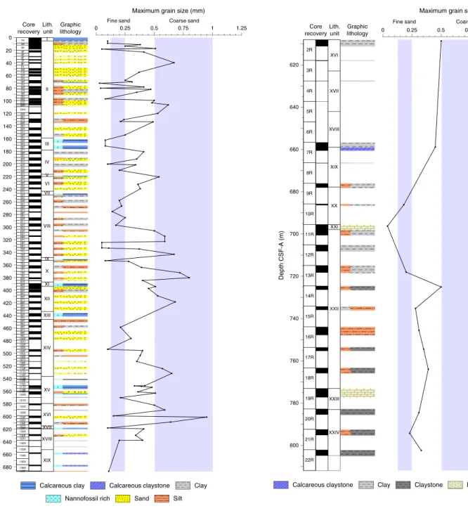
Recovered sediments from Site U1450 are divided into 24 litho-stratigraphic units based on lithologic and paleontological charac-teristics obtained through macroscopic and smear slide analyses and physical property measurements (Figures F4, F5; Table T2).
Unit summaries
Because of the lithologic similarities between units, they have been grouped by lithology and summarized. More detailed descrip-tions of individual units are presented in the subsequent secdescrip-tions.
Units I, III, V, VII, IX, XI, XIII, XV, XVII, and XIX are dominated by calcareous clays. Lower units (XI, XV, and XIX) contain pyritized burrows and/or intercalated clay and silt beds with plant fragments.
Units II, IV, VI, VIII, and XVI are principally siliciclastic sediments that fine upward (i.e., turbidites).
Units X, XII, XIV, XVIII, XX, and XXII are also dominated by siliciclastic sediment but are texturally homogeneous
Units XXI, XXIII, and XXIV are impure limestones and calcare-ous claystones with minor components of silty clay, claystone, and siltstone occasionally containing plant fragments.
Units I and VII contain ash layers.
Lithostratigraphic summary
Similar to Site U1449, lithologic differences between units and variations in grain size and bed thickness reflect cycles of proximal turbidity current channel activity and abandonment. Sand intervals may represent interlevee sheet flows (e.g., Curray et al., 2003), whereas finer grained fractions are more likely preserved in leveed sections. Bioturbated calcareous clays represent times of local chan-nel-levee inactivity and reduced siliciclastic deposition and reflect an increase in settling of pelagic material. Many intervals of calcare-ous material show repeated sequences of color-graded beds, which can occur because of increased entrainment of siliciclastic material, changes in water column productivity, or changes in the oxida-tion/reduction horizons of the pore waters. In Hole U1450B, inter-vals dominated by calcareous and/or clayey material become increasingly lithified with depth, and many are intercalated with very thin to thin silt or siltstone layers. Plant fragments occur throughout the site, more commonly in silt and siltstone intervals, although a few sand-dominated units also contain macroscopic or-ganic material. At the top of Hole U1450A is an 18 cm thick ash layer that presumably corresponds to the ~75 ka Toba volcanic eruption that produced widespread tephra deposits across the Bay of Bengal (e.g., Ninkovich et al., 1978; Gasparotto et al., 2000).
Overall, siliciclastic units (silt, clay, and sand) at Site U1450 are compositionally classified as mica rich (muscovite and biotite) and quartz rich. Sands occur mostly in fine to medium grain size ranges with rare occurrence of coarse-sized particles. Feldspar and heavy minerals (e.g., tourmaline, apatite, zircon, amphibole, garnet, sphene, rutile, chrome spinel, zoisite, glauconite, and opaque min-erals) are common in silt- and sand-rich layers, and metamorphic minerals (sillimanite and chloritoid) and lithic fragments (e.g., quartzite, gneiss, and schist) occasionally appear in sands.
Units containing calcareous sediment (limestone and calcareous claystone) are mottled and bioturbated, consistently include radio-larians and foraminifers, and often exhibit color variations from white to greenish gray. The nomenclature for lithologic descriptions of fine sediments containing carbonate consists of a principal name and a modifier based on the composition estimated from visual de-scription of the cores and from smear slide observations. The prin-cipal name of sediment that appears to contain >75% carbonate is calcareous ooze (see Figure F4 in the Expedition 354 methods chap-ter [France-Lanord et al., 2016a]). The principal name of sediment that appears to contain <10% carbonate is clay. If sediment contains a mixture of clay-sized siliciclastic particles and calcareous compo-nents (i.e., carbonate contents between 10% and 75%), the principal name is calcareous clay. This nomenclature was adopted to describe the continuum of sediments recovered from almost pure clay to al-most pure calcareous ooze. In al-most cases, lithologic names assigned using this protocol match well with measured carbonate content and accurately reflect the continuum of sediments recovered at this site. Examples can be seen in Figure F6 in the Site U1451 chapter (France-Lanord et al., 2016b) and Figure F5 in the Site U1452 chap-ter (France-Lanord et al., 2016c).
Drilling disturbances at this site vary in intensity from slight to high and include flow-in, fractures, up-arching, “soupy” textures, and drilling biscuits. Flow-in is the most common drilling distur-bance in fine-grained intervals, whereas disturbed sands may dis-play a homogeneous (or soupy) texture. See Figure F6 in the Expedition 354 methods chapter (France-Lanord et al., 2016a) for a more detailed description and graphic examples of drilling distur-bance types.
Unit I
Interval: 354-U1450A-1H-1, 0 cm, to 1H-4, 54 cm; Hole U1450B not recovered
Depth: 0–5.04 m CSF-A Age: Late Pleistocene–recent
Lithology: calcareous clay (major); volcanic ash (minor)
Figure F4. Lithostratigraphic summary, Hole U1450A. For legend, see Figure F5 in the Expedition 354 methods chapter (France-Lanord et al., 2016a). For a larger version of this figure, see LITHOSTRAT in Supplementary material. (Continued on next page.)
340 320 300 280 260 240 220 200 180 160 140 120 100 80 60 40 20 0 1H 2H 3H 4F 5F 6F 7F 8F 91 10F 11F 12F 131 14F 151 16F 17F 18F 191 20F 21F 22H 231 24H 25F 261 27F 28F 291 30F 311 32F 331 34F 351 36F 371 38F 391 40F 411 42F 431 44F 451 46F 471 48F 491 50F 511 52F 531 54F 551 56F 571 58F 591 60F 611 62F 631 64F 651 66F 671 68F 691 70F 711 72F 731 I II III IV V VI VII VIII P-wave velocity (m/s) 1760 1600 1440 Graphic lithology Core recovery GRA (g/cm3) 2 1.6 1.2
U1450A Hole summary
Magnetic susceptibility Loop Point (SI) 400 300 200 100 0 -12 -6 0 6 14 10 6 2 -2 Reflectance L*a*b* 68 48 28 8 Natural gamma radiation (cps) 95 75 55 35 15 Lith.
unit Drilling distu
rban ce Lith olo g ica l acc ess orie s De pth CS F-A (m )
Description
Unit I consists of a 5.0 m thick nannofossil-rich calcareous clay with foraminifers. The uppermost 20 cm is yellow and has a soft spongy texture. The color gradually changes downsection to light gray with mottling and abundant burrows. Intervals 1H-1, 19–66 and 108–141 cm, are particularly rich in planktonic foraminifers. Section 1H-2, 9–27 cm, contains a light brown volcanic ash layer composed of fine sand–sized glass shards fining upward (Figure F6). The base of this layer appears to have been disturbed by coring, and a blob of ash is found 32 cm farther downcore (1H-2, 59–65 cm). This ash blob does not appear to be a laterally continuous fea-ture; therefore, we interpret it to be a result of displacement by
cor-ing. Below the base of the ash layer is a 67 cm thick interval of white calcareous clay with large vertical burrows (>5 cm) infilled with dark material, probably pyrite framboids. Below this interval, the white calcareous clay becomes gray with a mottled texture. Intervals 20–50 cm thick of gray calcareous clay are divided by 1–2 cm thick bands of dark green calcareous clay. At the base of the unit (Section 1H-4, 48 cm), calcareous clay transitions into bioturbated gray clay with foraminifers.
Composition from smear slides
See Figure F7 for representative smear slide images.
Figure F4 (continued). 680 660 640 620 600 580 560 540 520 500 480 460 440 420 400 380 360 74F 751 76F 771 78F 791 80F 81F 82F 83F 84F 851 86F 871 88F 891 90F 911 92F 931 94F 951 96F 971 98F 991 100F 1011 102F 1031 104F 1051 106F 1071 108F 1091 110F 1111 112F 1131 114F 115F 1161 117F 118F 119F 120X 121X 122X 123X 124F 1251 126F 1271 128F 129X 130F 1311 132X 133X 134X 135X 136X 137F IX X XI XII XIII XIV XV XVI XVII XVIII XIX P-wave velocity (m/s) 1760 1600 1440 Graphic lithology Core recovery GRA (g/cm3) 2 1.6 1.2
U1450A Hole summary
Magnetic susceptibility Loop Point (SI) 400 300 200 100 0 -12 -6 0 6 14 10 6 2 -2 Reflectance L*a*b* 68 48 28 8 Natural gamma radiation (cps) 95 75 55 35 15 Lith.
unit Drilling distu
rban ce Lith olo g ica l acc ess orie s De pth CS F-A (m )
Nannofossil-rich calcareous clay
Calcareous nannofossils make up a significant proportion of the total grains in the smear slides, up to 85%–95%, with fragments of radiolarians, foraminifers, and diatoms (1H-1, 54 cm; 0.539 m CSF-A). Minor amounts of clay minerals are also found.
Volcanic ash
Smear slides from the ash layers mainly consist of volcanic glass shards 0.01–0.35 mm in diameter and minor amounts of quartz, feldspar, biotite, and hornblende. Volcanic glass appears in the form of clear plates, flakes, and strands with a relatively low refractive in-dex (1H-2, 64 cm; 2.14 m CSF-A). Occasionally, fragments of radio-larians and foraminifers contaminate the ash. The typical range for the volcanic glass proportion is 90%–95% of total grains.
Unit II
Interval: 354-U1450A-1H-4, 54 cm, to 32F-CC, 31 cm; Hole U1450B not recovered
Depth: 5.04–156.76 m CSF-A Age: Middle–Late Pleistocene
Lithology: clay, silt, sand (major); nannofossil-rich calcareous clay with foraminifers (minor)
Description
Unit II is generally characterized by alternating sequences of silt- and clay-rich (Figure F6B) and sand-rich intervals (i.e., turbi-dites) intercalated with calcareous clay between 70.79 and 72.41 m CSF-A. The silt- and clay-rich intervals are located at 5.04–11.6,
96.76–99.04, 128.82–134.4, and 151.9–153.35 m CSF-A. They usu-ally consist of repeated thin- to medium-bedded laminated silt fin-ing upward into clay (Figure F8A). The clays are either structureless or bioturbated (Figure F8B). The silts often exhibit an overall up-ward decreasing trend of thickness and frequency. The sand-domi-nated intervals mainly consist of medium to very thick beds overlain by thin- to medium-bedded clay layers with gradational boundaries. Thick to very thick sand beds often show a soupy tex-ture and are mostly composed of fine to medium normally graded sand, especially in the uppermost parts of the beds (Figure F8C). They also commonly show horizontal stratification with mica-rich or plant debris–rich layers (Figure F9) and occasionally include a few mud clasts.
Composition from smear slides
See Figure F7 for representative smear slide images. Calcareous clay
White and greenish white calcareous clay is mainly composed of calcareous nannofossils with radiolarians. The average proportion of the nannofossil component is 65%–80% of total grains. In some horizons, clay minerals and fragments of foraminifers occur (14F-3, 73 cm; 71.10 m CSF-A).
Clayey silt and silty clay
Silt-sized grains include quartz, feldspar, mica, altered mica, and heavy minerals. Clay-sized minerals include amorphous and apha-nitic grains (2H-1, 52 cm; 9.02 m CSF-A). Carbonate minerals are occasionally present.
Figure F5. Lithostratigraphic summary, Hole U1450B. For legend, see Figure F5 in the Expedition 354 methods chapter (France-Lanord et al., 2016a).
800 780 760 740 720 700 680 660 640 620 2R 3R 4R 5R 6R 7R 8R 9R 10R 11R 12R 13R 14R 15R 16R 17R 18R 19R 20R 21R 22R XVI XVII XVIII XIX XX XXI XXII XXIII XXIV P-wave velocity (m/s) 3450 1450 Graphic lithology Core recovery GRA (g/cm3) 2.5 2 1.5 1
U1450B Hole summary
Magnetic susceptibility Loop Point (SI) 150 100 50 0 -10 -5 0 12 9 6 3 0 -3 Reflectance L*a*b* 72 56 40 24 8 Natural gamma radiation (cps) 100 50 0 Lith. unit Drillin g di s tur b a nc e Lith olo g ica l acc ess orie s De pth CS F-A (m )
Table T2. Intervals, depths, major and minor lithologies, and ages of units, Site U1450. Download table in .csv format. Unit Interval Top depth CSF-A (m) Bottom depth
CSF-A (m) Major lithology Minor lithology Top age Bottom age
354-I U1450A-1H-1, 0 cm, to 1H-4, 54 cm 0.00 5.04 Calcareous clay Volcanic ash recent Late Pleistocene II U1450A-1H-4, 54 cm, to 32F-CC, 31 cm 5.04 156.76 Clay, silt Calcareous clay Late Pleistocene Middle Pleistocene III U1450A-34F-1, 0 cm, to 36F-CC, 37 cm 161.40 176.00 Calcareous clay Clay, silt Middle Pleistocene Middle Pleistocene IV U1450A-38F-1, 0 cm, to 44F-CC, 32 cm 180.40 213.75 Clay, silt, sand None Middle Pleistocene Middle Pleistocene V U1450A-46F-1, 0 cm, to 46F-1, 140 cm 218.40 219.80 Calcareous clay None Middle Pleistocene Middle Pleistocene VI U1450A-46F-1, 140 cm, to 50F-CC, 32 cm 219.80 240.13 Sand Clay Middle Pleistocene Middle Pleistocene VII U1450A-52F-1, 0 cm, to 52F-2, 82 cm 246.90 249.17 Calcareous clay Volcanic ash Middle Pleistocene Middle Pleistocene VIII U1450A-52F-3, 0 cm, to 72F-CC, 23 cm 249.17 345.61 Clay, silt Sand Middle Pleistocene early Pleistocene IX U1450A-74F-1, 0 cm, to 74F-2, 12 cm 351.40 352.98 Calcareous clay Clay early Pleistocene early Pleistocene X U1450A-74F-2, 12 cm, to 81F-1, 80 cm 352.98 385.40 Silt Sand, clay early Pleistocene early Pleistocene XI U1450A-82F-1, 0 cm, to 82F-CC, 22 cm 389.30 394.24 Calcareous clay None early Pleistocene early Pleistocene XII U1450A-83F-1, 0 cm, to 90F-3, 136 cm 394.00 431.13 Sand Clay early Pleistocene early Pleistocene XIII U1450A-92F-1, 0 cm, to 94F-1, 16 cm 436.70 446.36 Calcareous clay None early Pleistocene early Pleistocene XIV U1450A-94F-1, 16 cm, to 112F-1, 113 cm 446.36 532.83 Sand, silt Clay early Pleistocene early Pleistocene XV U1450A-114F-CC, 0 cm, to 121F-CC, 66 cm 541.20 570.57 Calcareous clay Sand, clay early Pleistocene middle Pliocene XVI U1450A-122X-1, 17 cm, to 126F-CC, 20 cm 579.77 612.51 Clay, silt Sand, clay, calcareous clay middle Pliocene middle Pliocene
U1450B-2R-1, 0 cm, to 3R-1, 23 cm 608.00 618.03
XVII U1450A-128F-1, 0 cm, to 128F-CC, 38 cm 618.00 619.90 Calcareous clay Clay early Pliocene early Pliocene U1450B-4R-CC, 0 cm, to 4R-CC, 12 cm 627.50 627.62
XVIII U1450A-129X-CC, 0 cm, to 133X-CC, 25 cm 619.90 648.14 Sand Clay, silt, calcareous clay early Pliocene late Miocene U1450B-7R-1, 0 cm, to 7R-2, 80 cm 656.50 658.90
XIX U1450A-134X-1, 0 cm, to 137F-1, 106 cm 657.20 687.36 Calcareous claystone Clay, silt, sand late Miocene late Miocene U1450B-7R-2, 80 cm, to 9R-1, 0 cm 658.90 677.80
XX U1450B-9R-1, 0 cm, to 11R-1, 11 cm 677.80 695.51 Clay None late Miocene late Miocene XXI U1450B-11R-1, 11 cm, to 11R-2, 94 cm 695.51 697.83 Limestone, calcareous
claystone
Clay late Miocene late Miocene
XXII U1450B-11R-2 94 cm, to 19R-1, 5 cm 697.83 773.05 Clay Silt, limestone late Miocene late Miocene XXIII U1450B-19R-1, 5 cm, to 21R-1, 39 cm 773.05 783.09 Limestone Calcareous claystone,
siltstone, claystone
late Miocene late Miocene
XXIV U1450B-20R-1, 39 cm, to 22R-CC 783.09 804.86 Claystone Siltstone, sandstone, calcareous claystone
late Miocene late Miocene
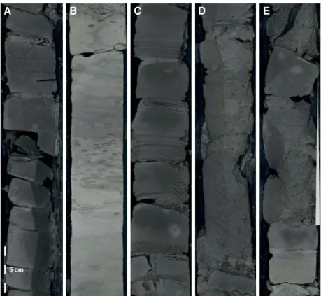
Figure F6. Representative examples of major lithologies recovered in Hole U1450A. A. Volcanic ash (1H-2, 5–37 cm). B. Succession of mud turbidites (1H-5, 1–33 cm). C. Silt/fine-sand dominated turbidites (42F-1, 22–54 cm). D. Homogeneous fine sand (40F-1, 77–109 cm). E. Nannofossil-rich calcareous clay (120X-3, 64– 96 cm). F. Centimeter-sized clasts of light gray nannofossil-rich calcareous clay in a matrix of clay (117F-1, 49–81 cm).
A
B
C
D
E
F
Silty sand
Silty sand layers intercalated in the upper part of the unit consist of quartz, feldspar, mica, and lithic fragments. Heavy minerals, in-cluding amphibole, tourmaline, zoisite, zircon, apatite, and opaque minerals, are frequently recorded. Metamorphic minerals such as sillimanite and chloritoid were occasionally observed. In several horizons, a few glauconitic grains, mostly 0.1–0.2 mm in diameter, are found. The sand at 20.20 m CSF-A includes a large amount of
plant debris and wood fragments with foraminifers. Occasionally, aggregate grains of carbonate minerals occur. The maximum grain size for sand grains is 0.67 mm in diameter (8F-1, 80 cm; 39.80 m CSF-A).
Unit III
Interval: 354-U1450A-34F-1, 0 cm, to 36F-CC, 37 cm; Hole U1450B not recovered
Depth: 161.40–176.00 m CSF-A Age: Middle Pleistocene
Lithology: calcareous clay (major); biosiliceous-rich clay, silt (minor)
Description
Unit III consists of 14.6 m of varicolored nannofossil-rich cal-careous clay with foraminifers and occasional 3–15 cm thick dark gray silt interbeds. The calcareous clay is mostly white-yellow with green and light gray intervals. Small horizontal burrows and mot-tling are pervasive. Vertical burrows occur less often and are gener-ally larger (>3 cm) and infilled with pyrite. From 34F-4, 0 cm, to 34F-CC, 36 cm, a biosilica-rich interval with radiolarians is present. The uppermost 5.1 m of the unit was recovered in Core 34F, fol-lowed by 4.4 m of drilling without coring. When coring resumed in Core 36F, another 5.2 m of this calcareous clay unit was recovered.
Composition from smear slides
See Figure F7 for representative smear slide images. Nannofossil-rich calcareous clay
Calcareous nannofossils make up a significant proportion (up to 85%) of the clay-sized fraction, and clay minerals occur in minor proportion (up to 10%). Radiolarians also contribute a minor amount, generally up to 5%.
Figure F7. Representative smear slide images (parallel nicols), Hole U1450A. A. Volcanic ash with abundant glass shards (1H-2; 1.600 m CSF-A). B. Silty sand including quartz, feldspar, and various kinds of mica and heavy miner-als (22H-2; 106.500 m CSF-A). C. Clay minerminer-als (2H-1, 9.020 m CSF-A). D. Nan-nofossil-rich calcareous clay (76F-1; 360.920 m CSF-A).
0.1 mm 1 mm
0.1 mm 0.1 mm
A B
C D
Figure F8. Hole U1450A features. A. Laminated silt overlain by structureless clay (2H-2A, 79–99 cm). B. Bioturbation in thin mud turbidites (32F-1A, 12– 32 cm). C. Two successive sand turbidites, boundary at 8 cm (28F-1A, 1–22 cm). Note fining-upward texture (normal grading) in the uppermost part of the lower unit and horizontal stratification in the basal part of the upper unit.
A
B
C
Figure F9. Plant fragments, Hole U1450A. A. Occurrence of plant fragments in basal part of sand turbidites marked by white ovals (4F-1, 91–104 cm). B. Microscope photograph of plant fragment. C. Microscope photograph of sand grains from the basal part of the sand turbidites, showing abundant plant fragments.
1 mm
A
B
Silt
Silt-sized grains of quartz, feldspar, lithic fragments, mica, and heavy minerals are found (34F-1, 108 cm; 162.388 m CSF-A). Occa-sionally, carbonate minerals, nannofossils, radiolarians, and their fragments are also present.
Unit IV
Interval: 354-U1450A-38F-1, 0 cm, to 44F-CC, 32 cm; Hole U1450B not recovered
Depth: 180.40–213.75 m CSF-A Age: Middle Pleistocene Lithology: clay, silt, fine sand
Description
Unit IV is characterized by overall dominance of medium- to thick-bedded sand beds intercalated with a few successive thin- to medium-bedded clay- and silt-rich intervals (i.e., turbidites; Figure F6C). Sand-dominated intervals are mostly composed of normally graded fine to medium sand. The grading is especially visible in the uppermost parts of the beds. Some sand beds display no internal structures, perhaps because of homogenization by coring (Figure F6D). However, they also commonly show horizontal stratification with mica. The intercalated clay- and silt-rich beds mainly consist of structureless clay with basal thin or very thin silt or sand layers. Basal silt or sandy layers are laminated and normally graded with sharp lower boundaries.
Composition from smear slides
See Figure F7 for representative smear slide images. Clayey silt
Clayey silt mainly contains detrital grains. Occasionally, nanno-fossils, radiolarians, and their fragments are also found. The miner-alogy of clayey silt is similar to that of silty sand, as described below, although the heavy mineral content tends to be richer compared to sand. Occasionally, carbonate minerals are also recorded.
Silty sand
Silty sand consists of quartz, feldspar, and mica. Organic mate-rial, such as plant debris, was frequently observed. As accessory minerals, heavy minerals including amphibole, tourmaline, zircon, garnet, chromian spinel, chloritoid, and opaque minerals are found. In several horizons, the proportion of heavy minerals is very low, less than 1% of total grains (40F-2, 85 cm; 192.28 m CSF-A). Occa-sionally, euhedral carbonate minerals and aggregate grains of car-bonate minerals are found. The maximum grain size is 0.41 mm in diameter (38F-1, 40 cm; 180.8 m CSF-A).
Unit V
Interval: 354-U1450A-46F-1, 0–140 cm; Hole U1450B not re-covered
Depth: 218.40–219.80 m CSF-A Age: Middle Pleistocene
Lithology: nannofossil-rich calcareous clay
Description
Unit V consists of 1.4 m of green to light gray nannofossil-rich calcareous clay. The uppermost 0.78 m is deformed and consists of broken pieces of calcareous clay in a liquefied matrix, probably fall-in from the fall-interval above that was drilled without corfall-ing.
Composition from smear slides
See Figure F7 for representative smear slide images. Nannofossil-rich calcareous clay with radiolarians
Calcareous clay is mainly composed of nannofossils and a greenish gray layer rich in radiolarians. A relatively high proportion of foraminifers was also observed. The average proportion of the nannofossil component is 50%–75% of total grains.
Unit VI
Interval: 354-U1450A-46F-1, 140 cm, to 50F-CC, 32 cm; Hole U1450B not recovered
Depth: 219.80–240.13 m CSF-A Age: Middle Pleistocene
Lithology: fine sand (major); silty clay (minor)
Description
Unit VI is characterized by overall dominance of medium-bed-ded to very thick bedmedium-bed-ded fine to medium sands. The uppermost part of the sand beds often shows normal grading. The sands are overlain by very thin to thin structureless clay layers with grada-tional boundaries and commonly show horizontal stratification with mica. Taking all characteristics into account, Unit VI mostly represents sand-dominated turbidites.
Composition from smear slides
See Figure F7 for representative smear slide images. Silty sand
Silty sand consists primarily of quartz, feldspar, lithic fragments, mica, and heavy minerals. All grains are angular except altered mica grains. Heavy minerals such as garnet, zircon, amphibole, apatite, tourmaline, sphene, and opaque minerals are present. Large grains of mica and quartz, reaching 0.5 mm in diameter, are ubiquitous. This lithofacies also contains fragments of foraminifers and aggre-gates of carbonate minerals as a minor proportion. The maximum grain size is 0.54 mm in diameter in this interval (46F-2, 77 cm; 220.62 m CSF-A).
Unit VII
Interval: 354-U1450A-52F-1, 0 cm, to 52F-2, 82 cm; Hole U1450B not recovered
Depth: 246.90–249.17 m CSF-A Age: Middle Pleistocene
Lithology: nannofossil-rich calcareous clay with foraminifers (major); volcanic ash (minor)
Description
Unit VII consists of 2.3 m of mottled white to light gray nanno-fossil-rich calcareous clay with foraminifers. Horizontal and vertical burrows are pervasive. Interval 52F-1, 9–21 cm, is a light brown vol-canic ash layer composed of fine sand-sized glass shards. The base of this ash layer shows a band of black coloration and has an irregu-lar sharp boundary with the calcareous clay beneath.
Composition from smear slides
See Figure F7 for representative smear slide images. Nannofossil-rich calcareous clay with radiolarians
Calcareous clay mainly consists of nannofossils, ranging from 85% to 90% of total grains. Few radiolarians and foraminifers were also observed.