The Design and Construction of Interactive
Architectural Environments
The Digital Mile, Zaragoza, Spain
by
Shutsu K. Chai
SUBMITTED TO THE DEPARTMENT OF MECHANICAL ENGINEERING IN PARTIAL FULFILLMENT OF THE REQUIREMENTS FOR THE DEGREE OF
BACHELOR OF SCIENCE AS RECOMMENDED BY THE DEPARTMENT OF MECHANICAL ENGINEERING
AT THE
MASSACHUSETTS INSTITUTE OF TECHNOLOGY
June 2006
©
2006 Shutsu K. Chai All rights reserved.ARCHIVES
The author hereby grants to MIT permission to reproduce and to distribute publicly paper and electronic copies of this thesis document in whole or in part
in any medium now known or hereafter created.
Signature of Author:
Department of Mechanical Engineering May 12, 2006 Certified by: 4 John Fernandez Associate Professor Thesis Supervisor Accepted by: John H. Lienhard V Professor of Mechanical Engineering Chairman, Undergraduate Thesis Committee
1
MASSACHUSETTS INSTIJITE OF TECHNOLOGY
I I
The Design and Construction of Interactive
Architectural Environments
The Digital Mile, Zaragoza, Spain
by
Shutsu K. Chai
Submitted to the Department of Mechanical Engineering on May 12, 2006 in Partial Fulfillment of the Requirements for the Degree of Bachelor of Science as Recommended by the Department of Mechanical Engineering
ABSTRACT
As a part of a master plan for the Digital Mile, a park in Zaragoza, Spain, this thesis will undertake the mechanical design and construction of a responsive and rearrangable system of walls and doors for increasing the flexibility of the "edge" between open space and a new museum building. In order to study this question, this thesis builds on a previous planning thesis and the prescribed architectural forms as a basis for investigation
of potential construction materials and joint technologies. Through this study, a design will emerge for this unique system that allows space to expand and contract and the building edge to become porous or sealed, responding to the demands for different activities and situations. Construction materials and mechanisms will be studied based on the functional requirements of the system. These investigations will lead to
recommendations for mechanical means to achieve the prescribed architectural and performance specifications. It is anticipated that this new building-edge will support a wider variety of activities and in this way enhance the livability and usability of public space. Beyond the physical design, this thesis will also demonstrate the ability of interdisciplinary work to enrich the design process.
Thesis Supervisor: John Fernandez Title: Associate Professor
Table of Contents
1. Introduction ... 7
2. B ackground ... 11
2.1 Kinetic Typologies ... 11
2.2 History of Deployable and Kinetic Environments ... 13
2.3 Materials ... 14 2.3.1 Metals ... 15 2.3.2 Polymers ... 15 2.3.2 Ceramics ... 16 2.3.3 Composites ... 17 2.3.4 Natural Materials ... 17 2.4 Mechanisms ... 18 3. Methodology ... 21
Mechanical Design In-depth ... 21
4. Performance Specifications ... 23
4.1 Environmental Standards ... 23
4.1.1 Exterior Standards ... 23
4.1.2 Interior Standards ... 23
4.2 Usage ... 24
4.3 Summary for Evaluation ... 25
5. Architectural Design ... 27
5.1 Flexible Armature ... 27
5.2 Design Evaluation ... 30
5.3 Most Promising Design ... 31
6. Mechanical Design ... 33
6.1 Mechanisms for Movement ... 33
6.1.1 Column and Deployed Material ... 33
6.1.2 Movement Mechanisms Above Column ... 35
6.1.3 Track System ... 44
6.1.4 Movement Mechanisms Below Column ... 48
6.2 Materials Selection ... 50
6.2.1 Wheels ... 52
6.2.2 Housing (for transmitter) ... 52
6.2.3 Column ... 56 6.2.4 Fabric Interior ... 62 6.2.5 Fabric Exterior ... 64 6.2.6 Remaining Mechanisms ... ... ... 65 7. Conclusion ... 68 8. References ... 70
Appendix A: Movement Mechanisms (above Column) Drawings ... 73
Appendix B: Track Mechanisms Drawings ... ... 83
Appendix C: Column Components Drawings ... 85
Appendix D: Fractal Geometries Background ... 86
Performance Specifications ... 89
Architectural Design ... 89
Appendix F: Performance Specifications ... 91
M useum of the M ile ... 91
Supportable Activities ... 91
Appendix G: Architectural Design ... 100
Design Exploration ... 100
I. Fractal Pathways ... 100
II. Fractal Arrangements ... 103
III. Flexible Armature ... 109
Design Evaluation ... 111
M ost Promising Design ... 115
II. Column Function ... 115
Table of Figures
Figure 1. Map of Spain, Zaragoza in Northeast ... 7
Figure 2. Urban Design Concept: The Digital Mile ... 8
Figure 3. Musuem Building, Second from Left ... 9
Figure 4. Potential configurations of doors based on a fractal ... 9
Figure 5. Hoberman Arch ... 12
Figure 6. Pantograph ... 12
Figure 7. Airtecture Hall ... 13
Figure 8. Walls Extend from Columns, Only Supported by Column ... 27
Figure 9. Single Column Rotation and Extension Methods ... 28
Figure 10. Double Column Extension Method ... 28
Figure 11. Three-Column Clusters with Fabric Deployed Between Columns ... 29
Figure 12. Three Potential Methods of Lifting Columns out of Space: 1. Straight Up, 2. Rotate Up with Vertical Deployment, 3. Rotate Up with Horizontal Deployment .... 29
Figure 13. Example: Vertically Deploying Window Shade ... 30
Figure 14. Obstacles in Design Exploration for Hinged Column Material Deployment.. 32
Figure 15. Column with Exploded View, Rotational Spring Noted ... 34
Figure 16. Deploying Material Between Pair of Columns ... 35
Figure 17. Wheel, Bearings, & Axle Setup ... 37
Figure 18. Base Unit Block Diagram ... 41
Figure 19. Handset Unit Block Diagram ... 42
Figure 20. Context Model with Longest Diagonal Marked . ... 43
Figure 21. Metal Housing ... 44
Figure 22. Rotating Track Component, Isometric View . ... 45
Figure 23. Underside of Rotating Track, Carriage Location Noted ... 46
Figure 24. Circular Cut Rotating Track, Plan View ... 46
Figure 25. Track Rotational Mechanisms, Motor Location Noted ... 47
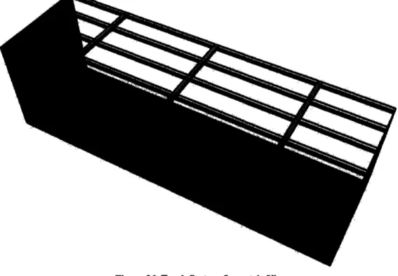
Figure 26. Track System, Isometric View ... 48
Figure 27. Nylon Bristles on Toothbrush ... 49
Figure 28. Typical Ashby Diagram ... 50
Figure 29. Trade-off curve between strength and weight ... 51
Figure 30. Roller-blades with Polyurethane Wheels ... 52
Figure 31. Resistivity vs. Price, 1 x 10⁵ Resistivity Threshold ... 53
Figure 32. Resistivity vs. Density ... 54
Figure 33. Fracture Toughness vs. Density, Foams in Lower Left ... 55
Figure 34. Vickers Hardness vs. Density ... 56
Figure 35. 1/Young's Modulus vs. Density, Potential Materials Labeled ... 57
Figure 36. I/Young's Modulus vs. Density, Additional Materials Labeled ... 58
Figure 37. Shear Strength vs. Density, Woods Labeled ... 59
Figure 38. Price vs. Density, Balsa Compared to Ultra Low Density Wood ... 60
Figure 39. Modulus of Rupture vs. Density, Low Density Materials compared to Polymers (PUR = Polyurethane, PVC = Polyvinylchloride, PE = Polyethylene) ... 61
Figure 40. Polymer Comparison for Interior Fabric Selection ... 63
Figure 41. Column with Dimensions for Volume Calculations ... 66
Figure 43. Koch Curve ... 87
Figure 44. Flat, "Line" Edge ... 92
Figure 45. Open Edge Model ... 92
Figure 46. Stalls Configuration Model ... 93
Figure 47. An makeshift stand at the weekly Boston Haymarket ... 94
Figure 48. Serrated Edge Model ... 94
Figure 49. Enclosed Edge Model ... 95
Figure 50. Free Form Edge Model ... 96
Figure 51. X-Ray Machinery on crossing tracks at MIT Medical ... 102
Figure 52. Potential Configurations for Doors on Sliding Bearings ... 103
Figure 53. Dragon Curve Fractal Series ... 106
Figure 54. Sierpinski Gasket Fractal Series ... 108
Figure 55. Dragon Curve with 17 Distinct Wall Segments Numbered ... 116
1. Introduction
The Department of Urban Studies and Planning at MIT has been given the opportunity to develop a proposal for a new park in Zaragoza, Spain1 called the Digital Mile. As a part of that proposed master plan, this thesis will develop the urban and mechanical design of a reprogrammable museum building "edge."
Located in the northeastern part of central Spain and in close proximity to the Mediterranean Sea, the city has a maritime climate with mild winters and summers (Figure 1).2 The city is an industrial and trade center as well as a busy railway junction, annually hosting the National Trade Fair.3 Given the various social and business
activities of Zaragoza and its mild climate, the outdoor open spaces are an important part of the city.
Figure 1. Map of Spain, Zaragoza in Northeast4
Public spaces and the events that occur within these spaces are an integral part of the city's identity.5 Public spaces create places for markets, community gatherings, business transactions, tourist attractions, art and public performances, drawing people together for a myriad of purposes. As such, public spaces can help make a city distinct
Zaragoza is the capital city of the former kingdom of Aragon. In the last two millennia, Zaragoza has passed through many hands, most notably Roman and Moorish rule; even today, Roman and Islamic architecture remain part of the city. ["Zaragoza" (2005). Encyclopedia Britannica Online, Encyclopedia Britannica.]
2 "Spain" (2005). Encyclopedia Britannica Online, Encyclopedia Britannica. 3 "Zaragoza" (2005). Encyclopedia Britannica Online, Encyclopedia Britannica.
4 Factbook, The World (2005). Map of Spain. The World Factbook. C. I. Agency, Central Intelligence Agency: Map of Spain.
5 "A New Book on 'Event Places': Designing More Effective Public Spaces." PLAN, MIT School of Architecture and Planning Volume, DOI:
and viable because they draw residents and visitors alike. Therefore, careful design of public spaces and their associated events are critical pieces of any urban design.
With the introduction of Spain's newest high-speed train AVE to Zaragoza in the spring of 2004, the mile-long stretch of land that the former railway corridor occupied was made available to become a mile-long area for development, public facilities and open spaces dubbed "The Digital Mile" (Figure 2).6 The Digital Mile will be a unique public space because it will be linked by wireless internet access for computers, or in other words, information access. In addition to creating information accessible places, the park will also include an identifiable and attractive museum building front that is responsive to and functional for a variety of groups and activities (Figure 3).7
-& Im
41 s w _w -i
Figure 2. Urban Design Concept: The Digital Mile
6 "AVE Spain High-Speed Rail Network, Spain." Retrieved November 28, 2005, from http://www.railway-technology.com/projects/spain/.
7 The museum type is also still undefined at this time. Potentially, the use may respond to the design rather than demanding the design to respond to the museum type.
Second from Left.'
In order for space to be both responsive and functional, it must also be flexible in its openness to the public. Yet, spaces whether public or private are frequently defined by fixed boundaries such as walls and fences, leaving little ambiguity about where inside begins and outside ends. The Digital Mile will try to capture ambiguity in the design of the front of its museum building to improve the versatility of the space. The design for the front will be both open and accessible - as is its wireless network. To accomplish the objectives of openness and accessibility, this thesis will study and develop a system of movable walls and doors that blur the boundaries between what is inside and what is outside and allow the building edge to permeate the open space around it. Figure 4, created by Professor Dennis Frenchman is an example of what such a system might be with a system of doors that can rotate into a set of arrangements (Figure 4).9
/ _F r · " _n- - 20LaroMi do _ _ _ _ \ o f 'x ~ ' T M · ',' .. -,w x , w- ,, wN ' _ -L3 I 1'>i I \ - - \ / j-/ \ / \ /
Figure 4. Potential configurations of doors based on a fractal
8 Frenchman, Demnnis (2005). Layers of Media Video Conference 4. Cambridge, Massachusetts Institute of
Technology: 40. 9 Ibid.
Several specific functional requirements have been set at this time relating to usage and size constraints. The rearrangement of parts will likely occur several times a day, or at least on a daily basis. Thus, the design must be simple enough to move
frequently and in short periods of time. As this system will be a part of the building edge, the ability to seal off the building edge and to be weather resistant will be important characteristics. While not necessary in the climate of Zaragoza, the possibility of thermal insulation and air conditioning may prove useful for implementation at other sites. Finally, the geometric requirements of this system will be a height of 30 feet, a length of
100 feet, extending 30 feet into and 30 feet out of the building.
Through exploring existing examples of responsive architecture, further design criteria can be established for the building edge. These criteria will focus on the specific uses and flexibility required. The optimal arrangement and function of this system will emerge from those criteria. Once the optimal arrangement or arrangements and functions are established, this study will focus on developing the plans for a more detailed
mechanical design for the actual construction of the system. This process will include material selection and the joint technologies necessary for the movable parts to function.
The next section reviews existing examples of kinetic architecture in order to provide a starting point for this study. Next, a set of design criteria are developed for the project. Finally, through modeling, an actual responsive system will be designed and engineered.
2. Background
Portable architecture and deployable structures have been present throughout history in different forms. Many everyday examples exist, including something as simple as a tent or mobile home to forms as complicated as the retractable stadium dome at Minute Maid Park. From the tent to the mobile home to the retractable stadium dome, many everyday examples exist. In the evolution of architecture, these structures have gained complexity and grown increasingly innovative. Portable and flexible elements allow the transport or alteration of environments, and the advantages associated with this type of architecture are a result of the flexibility to accommodate to different sites, functions, activities and needs.1 0
2.1 Kinetic Typologies
There are four distinct kinetic typologies: pneumatics, pantographs, structural fabrics, and hinges or sliding elements. More specifically, these four typologies are a combination of deployable and portable structures. The unfolding nature of deployable architecture allows a small collapsed system to expand into a significantly larger structure. Portable structures are completely transportable structures. Pantographs are hinged struts that can expand and contract; for example, Figure 5 shows the Hoberman Arch designed by Chuck Hoberman (Figure 5). Looking at just a small portion of the whole, the struts rotate at the hinges allowing the pantograph to extend and draw back
(Figure 6). Pneumatic structures such as Airtecture Hall, are easily transported and erected inflatable buildings (Figure 7). A simpler example is a moon bounce, a structure that is often seen at traveling carnivals. Structural fabrics, which are lightweight and flexible, include structures as commonplace as tents. Finally, hinges, sliding elements and other moving joints permit and guide movement. Examples include door hinges and
sliding windows. The potential designs for this project will deal with one or a
combination of these typologies; the structures may combine the ability to deploy or un-fold with the ability to move and rearrange. While pneumatic structures are useful for their simplicity of erection, this research will exclude pneumatics.
r igure 5. nooerman
Arch--Figure 6. Pantograph'2
11 Barista, Dave (2001). "Retractable Arch Will Star at Olympics." Building Design and Construction
42(12): 1.
Figure 7. Airtecture I
2.2 History of Deployable and Kinetic Environments
In the field of deployable and kinetic structures, significant research has been done on the form that these structures should take and how best to design the various parts for the intended kinetic functions. Several leading researchers in this field include: Korio Miura from Japan, Mamoru Kawaguchi from Hosei University, Felix Escrig from the University of Seville, Waclaw Zalewski from the Massachusetts Institute of
Technology, and The Deployable Structures Laboratory at the University of Cambridge. 4
Beyond the bare mechanics of these structures, other researchers and designers have sought to make these structures art forms that respond in design to nature, beauty and usage requirements. Chuck Hoberman is also a prominent inventor of deployable structures, but with a greater focus of the structures for art rather than architecture.1 5 For Santiago Calatrava, forms in nature, particularly human form, provide the ideal
prototypes for the overall design of kinetic architecture.16 The Archigram group, led by
Peter Cook, were visionaries of portable, kinetic and reprogrammable architecture that give the user the power to transform and adapt their own buildings, communities and cities.
With growing demands for versatile building structures in the last 30 years, architects and engineers have joined together to develop innovative solutions to respond. Simple examples of reprogrammable space include doors and room partitions. Gunter Henn designed the KonzenForum for Volkswagon with two sets of six 60-foot-high glass
doors that function like vertical blinds, opening the space for natural ventilation and an
'3 BauNetz Airtecture Hall.
14 Gantes, Charis J. (2001). Deployable Structures: Analysis and Design. Southampton, Boston, WIT Press. 5
Ibid.
1
6 Adda, Catherine (2000). Santiago Calatrava "God Does Not Throw Dice". L. F. D'ici. Zurich, Sehfield Film and TV Producktionen AG.
"indoor piazza. ' 8sAnother more complex example is the Mobile Classroom Project by FTL Design Engineering Studio and Todd Dolland. This project includes a set of unfolding walls to expand the enclosed space from a 1.5 meter long trailer to a 50 square meter classroom, thus allowing ease in transportation when folded and ease in erecting the structure as the process is simply unfolding the trailer.19 A third example is
Lightweight Structures Unit and Arena Seating's mobile canopy system that consists of a cantilevered arch that is raised and lowered with a winch.2 0 Flexible and made of
lightweight materials, aluminum with a membrane stretched across, and this canopy is versatile and easily portable.21 In another relevant model, the Bristol Development Corporation Marketing Center, the building structure is folded into a large mast which expands like an upside-down umbrella after the base of the mast is secured in the
ground.2 2
2.3 Materials
The potential designs for this building edge depend on available materials, their properties, and the ability of the material to meet the functionality that the design criteria require. Industrial and natural are two broad groupings for these materials. There are
four major families of industrial materials: metals, polymers, ceramics and composites.2 3 From those broad industrial categories and natural materials, this investigation will focus on those materials that are useful to kinetic architecture, namely those that are lightweight while still having significant strength. In addition, weather resistance will also be
essential to the design of this system as portions of this system may be exterior to the museum building.
Important material properties include ductility, malleability, density, strength, elasticity, durability and weather resistance. Ductility refers to the ease of a material to be drawn into a wire or flattened into a sheet. Malleable materials are easily workable.
Density is measured in weight per volume, and consequently provides a relative measure of weight. Strength is typically assessed by a measure of the compressive and tensile strength that a material can withstand.2 4 Elasticity is a measure of how much a material can deform elastically, or in other words, deform without permanently deforming.2 5 Ideally, the structure will be lightweight so that it will be easily moved. Potentially, flexibility may add another element to the capabilities of the system.
'8 Weber-Hof, Claudine (2000). "Autostadt Wolfsburg, Germany; Gunter Henn's Corporate Theme Park for Volkswagen Engages Modern Architecture to Celebrate the Realm of Product Branding." Architectural Record 188(11): 148.
19 Kronenburg, Robert (2003). Portable Architecture. Oxford, Elsevier/Architectural Press.
20
Ibid.
21 Ibid.
2 2
Ibid.
23Fernandez, John (2006). Material Architecture: emergent materials for innovative buildings and
ecological construction. Boston, Architectural Press.
24
Ibid.
25 For example, a rubber band deforms elastically when it is stretched and returns to its original shape when the force is released. In contrast, taffy stretches and is permanently deformed.
2.3.1 Metals
In the family of metals, there are two large categories: ferrous and non-ferrous, or in other words, iron-bearing and non-iron-bearing. Important characteristics of metals relevant to this project include ductility, high strength, hardness and durability. Steel and especially stainless steel are key ferrous metals used for structural situations. Cast irons may also be utilized for smaller and shorter components such as bearing plates. The primary difference between steel and cast irons is their carbon content, where higher carbon content increases strength but decreases ductility. Stainless steels contain at least 10.5 percent chromium; this metal addition and the addition of copper, nickel, titanium, silicon, molybdenum, aluminum, nitrogen and sulfur contribute to the corrosion
resistance of stainless steel.2 6
Aluminum, copper and zinc are common non-ferrous metals that are possible construction materials. The 6000 series of aluminum are considered the architectural alloys and can be used for structural elements. Aluminum is considered a light metal with good strength and stiffness relative to its weight in addition to a low density. Copper and zinc sheeting and their alloys of bronze and brass are also useful metals because of their ductility and capability of enduring more wear. Copper has a particularly high ductility and mechanical workability. All three metals-aluminum, copper and zinc-are also corrosion resistant, a characteristic essential to enduring varying weather conditions.2 7
2.3.2 Polymers
Polymers are long chains of small molecules called monomers. Because of length of these chains, polymer properties are largely dependent up the arrangement of those chains and interactions between those chains and their subparts (Picture p.162). The
three primary categories of polymers are thermoplastics, thermosets and elastomers. Thermoplastics are those plastics that can be recycled, or in other words, melted and reformed repeatedly; their polymer chains are not chemically bonded and thus, can slide with respect to one another when heated. The structure of thermosets with cross-linking between chains and parts of chains cannot undergo the same process of reformation as the bonds prevent themosets from returning to a liquid state. The relevant thermosets are epoxy resins which will be discussed later in the composites section. Between a solid and a liquid, elastomers exhibit elastic elongation 300%-800% its original length.2 8
Transparent thermoplastics often serve as lighter weight substitutes for glass. Polycarbonate (PC) is a common glass substitute that is hard, durable and UV resistant, but subject to scratching and moisture damage. Ethylenetetrafluroethylene (ETFE) is another common glass substitute, but unlike PC, ETFE is non-rigid and thus, must be held in tension. ETFE is also UV resistant and strong in tension and is generally used to infill an area.2 9
26
Fernandez, John (2005). Meeting with Professor Fernandez. S. Chai. Cambridge: Materials survey with Professor Fernandez..
27 Ibid.
28
Fernandez, John (2006). Material Architecture: emergent materials for innovative buildings and ecological construction. Boston, Architectural Press.
29Fernandez, John (2005). Meeting with Professor Fernandez. S. Chai. Cambridge: Materials survey with
Nylons are also key thermoplastics. Nylon 6 is a flame resistant material, a beneficial characteristic. Ripstop nylon is made of a heavy thread in an approximately half centimeter grid and is thus durable and difficult to rip. Because of its strength and durability, this nylon is useful outdoors in places with strong winds; large kite-makers in Japan often use this material because of its strength and ability to withstand substantial
ripping.3 0
Several thermoplastics can be used as non-rigid fibers in structural fabrics. Polyethylene (PE) and polypropylene (PP) are the two most produced synthetic polymers that can be used as structural fabrics. Polyurethane (PUR) and Polyvinyl chloride (PVC) can be used as Teflon coated structural fabrics. Aramid fibers such as Kevlar are useful for reinforcing composites.31
The last two categories, thermosets and elastomers, have fewer relevant materials. The thermosets of interest are epoxy resins which will be discussed later as a part of the composites section. Important elastomers in kinetic architecture are the silicones which are inorganic polymers. Useful characteristics of silicones include resistance to
chemicals, oxidation and water, stability at high temperatures, non-conductance and high
elasticity.3 2
2.3.2 Ceramics
Ceramics are brittle and hard materials which can be classified as vitreous, glass, stone and concrete. Stone will not be considered as they are too heavy and dense for a kinetic system. Vitreous ceramics are fired metal minerals such as bricks or tiles. The most common glass is made of soda lime silica. Concrete is a mixture of cement, water and different sized aggregates.3 3
Glass is a particularly interesting material given its light transmission properties and existing glass technologies that allow the properties of glass to change on demand. Given that ability to change, glass has the potential to further increase the flexibility and reprogrammability of the museum building edge.
Glass is a super-cooled liquid derived from the fusion of silicon, boron,
germanium, phosphorus and arsenic oxides cooled to a rigid state without crystallizing.3 4 The lack of a crystalline structure permits light rays to pass through glass without
scattering while still absorbing ultraviolet radiation of wavelengths less than 315nm and greater than 3000nm.3 5 Glass has high strength and hardness, but cannot plastically deform and is consequently very brittle with a low tensile strength.36 The appearance and thermal properties of glass can be changed through coatings, sandwiched layers, added impurities and actuated changes in its crystalline structure.
Actuated changes in glass are particularly important for this research as this potentially adds another layer of responsiveness and changeability to the system. There
3 0
Ibid.
31 Ibid.
3 2
Ibid.
33 Fernandez, John (2006). Material Architecture: emergent materials for innovative buildings and ecological construction. Boston, Architectural Press.
3 4
Compagno, Andrea (1995). Intelligent Glass Facades: Material. Practice. Design. Berlin, Birkhauser Verlag.
35
Ibid. 36 Ibid.
are glass types and sandwiched layers that vary in color and transparency with light, temperature, and applied voltages which can be exploited in this study.3 7 In addition,
laminated glass can also be used with a structural fabric where the sandwiched fabric is used to hang the glass.3 8
Of the different types of concrete, aerated autoclaved concrete (AAC) is of interest for kinetic architecture because of its light weight and strength. AAC is essentially a foamed concrete with a cellular structure, a structure similar to a sponge dipped in plaster. AAC's cellular structure allows the material to be light weight and thus easily moved. Typically in the form of panels, blocks or long slabs, AAC is generally used as a rigid core rather than as a stand-alone panel or block as concrete is prone to
chipping.3 9
Ductal is an ultra high performance concrete known for its ductility and high strength. This fiber-reinforced material is capable of significant bending before
fracture.4 0 In addition, Ductal is capable of withstanding 200MPa of compressive force and 40MPa tensile force. Ductal's durability and resistance to environmental "attack" also make Ductal a useful material to consider for this reprogrammable system.41
2.3.3 Composites
Composites are formed of combinations of the above materials. While there are many types of composites, this study will limit the considered composites to pultrusions, a fiber reinforced polymer. Pultrusions are made of fibers pulled through an epoxy resin and then through a die that shapes the fibers.4 2 Listed in order of increasing strength and
cost, carbon, aramid or Kevlar and E-glass fibers are used to create pultrusions.4 3
Compared to wood and metal products, pultrusions are more corrosion resistant and light weight, two characteristics important for this outdoor kinetic system.4 4 In addition,
nearly any shape with a constant cross-section can be pultruded.4 5
2.3.4 Natural Materials
Natural materials, unlike industrial materials, require less processing and thus create more savings on the production side. Relevant natural materials include bamboo, wood and natural fibers. While bamboo is stronger than steel and significantly more lightweight, the difficulty and cost of acquiring bamboo in Spain leads this study to exclude bamboo from consideration. Wood is a biomaterial that has been used in building from the earliest structures and can be used as a structural material. Natural fibers include straw, flax, jute and sisal; these fibers are used in fabrics when woven
37 Ibid. 38
Fernandez, John (2005). Meeting with Professor Fernandez. S. Chai. Cambridge: Materials survey with Professor Fernandez..
39
Ibid.
40 Ibid.
41 Lafarge, Bouygues. (2002). "Ductal." Retrieved December 13, 2005, from http://www.ductal.com.
4 2
Fernandez, John (2005). Meeting with Professor Fernandez. S. Chai. Cambridge: Materials survey with Professor Fernandez..
43 Ibid.
44 Creative Pultrusions, Inc. (2002). ""The World's Most Innovative Leader in The Fiber Reinforced Polymer Composites Industry." ".
45 Strongwell. (2005). "Pultruded Products." Retrieved December 13, 2005, from http://www.strongwell.com/PultrudedProducts/Custom.htm.
together. Fabrics may be a useful flexible and lightweight material for use as part of the kinetic elements in this study.
2.4 Mechanisms
Mechanisms are an integral component of this study as movement is what makes this building edge digital and thus, makes this new building-edge a compelling part of The Digital Mile. Where digital is defined by open access and discreet elements, the reprogrammable aspect of this building-edge is the primary link to the rest of The Digital Mile. Rearranging the partitioning walls will create a set of unique configurations while the flexibility of space will permit the museum front to be open and accessible. Thus, the importance of movement to this system demands careful design and selection of the mechanisms.
Through a survey of general mechanism categories, this thesis will develop a better understanding of what motions will be mechanically feasible and how to begin designing the mechanisms to control and create desired movement. There will be multiple ways of achieving any general type of movement, but those designs will be narrowed down to those that best support the functional requirements of this building-edge. Machines are generally used to aid in repetitive actions or to facilitate tasks that are difficult or impossible to accomplish manually. This section will survey mechanisms that permit these motions, including repetitive, intermittent, reversing, reciprocating, differential and straight-line motions. In addition, this survey will also touch on stopping, hydraulic and automatic feeding mechanisms.
Repetitive motions are a key element in this project; elements of this system must be able to move many times, and often in the same way from day to day, hour to hour, or in other words rearrangeable and reprogrammable. Cams are mechanisms that are used for elements that revolve, oscillate or slide, where the cam is a rotating element that has edges and grooves that impart a motion to a follower. Cams allow the follower to repeatedly travel in variable and complex paths as the cam rotates. A common example..
Intermittent motions are a subcategory of repetitive motions, but involve a pause between repeated motions. As the walls of this building edge will be stationary for
stretches of time, periods of movement are intermittent. Although the overall movement is intermittent, the application of an intermittent mechanism is more relevant to the study of how to introduce precision to the placement of moving elements. The most basic example of a mechanism that imparts intermittent motions is the ratchet gear, much like a notched cam, where a follower encounters gradual movement and sudden pauses. A particularly useful mechanism for intermittent motions would be the Geneva wheel, a mechanism often used on machine tools to rotate a part of the machine through a fraction
of a revolution.4 6
Differential mechanisms allow precise movements as differential motion is the "resultant or difference between two original motions."4 7 This differential resultant can be precise at values significantly smaller than the original motions, thus allowing for more precise movements. A good example of a differential mechanism is the differential screw. A differential screw has two sections of threads at different pitches. The resulting
46
Jones, Franklin D., Ed. (1930). Ingenious Mechanisms: Volume 1. Ingenious Mechanisms For Designers and Inventors. New York, Industrial Press Inc.
4 7
differential motion is the difference between the two pitches, allowing for a slight motion without using a very fine pitch or weak thread.4 8 As the armature of this building edge is shifted from location to location to reconfigure the open space, the precision in placing each kinetic element will be important. For example, if a configuration is supposed to create walls that form a rectangular room, if the corners are not right angles, the
usefulness of the space is compromised; tables may not fit into corners where the angle is less than ninety degrees.
Reversing motions are needed to retract elements, particularly those elements that travel linearly. While this system may involve hinged, rotating elements, this system may also potentially involve elements traversing the entire open space. With elements that may need to move from one end of the space to the other, the reverse, or returning motion is equally as important as the initial forward motion.
Reciprocating motions are those that translate rectilinear motion to rotational motion or vice versa.4 9 This translation may be needed to drive movement from a single location while the elements of the system reach far beyond the mechanism's actuator. A good, simple example of this would be a rack and pinion set-up, with a small rotating gear, or pinion, moving on a flattened gear called a rack. Here, the rack translates the rotational motion from the motor and pinion into linear movement. This may be useful concept, where a rotational actuator drives linear movement, as either the actuator with the kinetic element attached can move along a rack, or the rack can be extended from a fixed actuator.
Stopping mechanisms will be a key component of this system; whatever object is moved from one point must be stopped at another and fixed there. There are two types of stopping mechanisms: one stops only once and must be reset again by hand, and the other can trip again and again periodically or at regular intervals.5 0 The latter type is of greater
interest, as this reprogrammable system should be automated and not require manual resetting. For these mechanical tripping mechanisms, there are three methods: clutches, shifting belts, and disengagement gearing. A clutch as a stopping mechanism separates a driving member, or the source of power, from a driven member. Belts are shifted
generally to control an entire machine's start or stop. Gears that engage and disengage are also capable of starting and stopping a machine or object. Selecting stopping mechanisms requires consideration of the speed of the moving objects, their inertia, and other factors such as how much shock the set-up can withstand.5 In addition to
mechanical tripping mechanisms, there are also electronic tripping mechanisms;
generally electronic tripping mechanisms are used only when they simplify a mechanical mechanism.52
Finally, there are hydraulic transmissions and automatic feeding mechanisms which may have a limited relevance to this project. Hydraulic operation of machines has several advantages over mechanical operation including quiet operation, lower power consumption, fewer moving parts, and fewer wearing parts, resulting in greater reliability
4 8 Ibid. 49 Ibid. 5o Ibid. 5' Ibid. 5 2 Ibid.
and lower maintenance and operation costs.3 Automatic feeding machines are not intuitively relevant, but this building edge will likely make use of several if not many of the same element. Consequently, although automatic feeding is typically applied to feeding parts to a machine in the manufacturing or machining process, some of the underlying concepts for managing multiple identical elements may be applicable.
5
3. Methodology
This project is divided into three stages: investigation of the problem and program definition; architectural design; and mechanical design. Investigation of the problem or architectural program is essentially defining what types of uses and activities that the building-edge will need to support. Architectural design outlines what general form the building-edge should take to meet needs of the architectural program. Mechanical design focuses on how to build the architectural design, including the construction materials and the mechanisms that will allow movement and reprogramming of the system.
The focus of this thesis will be the last stage of mechanical design. The first two stages have already been completed in a separate planning thesis; the methodology of the first two sections are included in Appendix E. The most promising approaches from the first two stages will be investigated in more detail in this engineering thesis through a focus on mechanical design. Through evaluating designs against the set of functional and performance requirements, the best architectural form will emerge, setting the stage for the in-depth research of the mechanical elements of the system.
Once the architectural design ideas have been assessed and the one or two best ideas have been selected, the mechanical design of the system can begin. Following the investigation of mechanical design, the project will return to a second stage of assessing the proposed architectural forms, but this time with attention to the mechanical feasibility and cost of construction. At this point, the final architectural form will be selected, and the project can enter the final stage of mechanical design in which the mechanisms for the best architectural forms are selected and designed with even greater detail.
The mechanical engineering research investigates the kinetic typologies and materials that this responsive environment requires, and in this way, this thesis also articulates a design methodology for kinetic architecture. Through looking at relevant examples of other types of kinetic and portable architecture and deployable structures, a toolkit is developed containing mechanical and architectural elements that can be used as portions of the kinetic system. By using this toolkit as a starting point. the mechanics and architecture evolve and take their own form.
Next, design of the mechanical system will respond to the functional requirements through the materials selection process and design of necessary mechanisms for
movement. 3D computer modeling will also aid the understanding of the kinematics of the proposed solutions. Ultimately, this project consists of two parallel design tracks at different scales: the macroscopic scale of the building and the mesoscopic scale of the individual components that comprise the kinetic system, the focus of this thesis.
Mechanical Design In-depth
The mechanical design is the smaller scale of design that focuses on how any architectural design idea can physically be built. Drawing from the movement
requirements of the architectural design, the functions of the kinetic system are defined. The definition of function leads into two parallel tracks: mechanisms and materials. The mechanisms track explores the potential joint and movement technologies required to move elements of the building edge. The materials investigation involves the assessment and selection of the relevant materials that support the functional requirements of this flexible building edge.
The exploration of function draws on the definition of the architectural program, or in other words, function outlines the general armature movements that will support activities in this space. For example, there are several potential options for the function definition of a window: sliding up and down; swinging in and out, attached to the
building at the top; and swinging in and out, attached to the building at the side. Defining the functions of this system ultimately amounts to movements and characteristics
necessary to achieve the architectural program. More broad examples of these characteristics include whether components of the system will be suspended, permit movement, or provide a secure building edge.
Investigating the joint and movement technologies brings the study to a still smaller scale, delving in to how the functional requirements can be achieved. This portion of the project will proceed through looking at mechanism precedents to identify a set of mechanisms that can be used to move the armature in the desired manner. This process will include the definition of functional requirements of the system such as speed control or strongly fixed positions and the characteristics of the system such as the weight of the elements to be moved. Through a more detailed study of existing mechanisms and their variations, this study will select the most appropriate mechanisms to achieve the reprogrammable building-edge.
The materials selection process addresses both the functional requirements of the larger architectural design and the mechanical design. Proper materials will be important to achieving performance specifications such as weather-proofing, security, digital-projection capabilities, and photo-sensitivity. Carefully selected materials will also affect the usefulness of the system, including moveability of elements, durability of the entire system over time, and robustness of the mechanisms. Materials will be assessed and selected through a program that Professor John Fernandez5 4 has helped to develop, the Cambridge Engineering Selector by Granta Design. This program will output a range of potential materials given an input of desired material properties. For the specific
functional requirements of the larger system, materials will be carefully selected to achieve those demands.
54 John Fernandez is a professor in the Department of Architecture at the Massachusetts Institute of Technology. He is also a part of the Building Technology Group, a group comprised of architecture and engineering faculty.
4. Performance Specifications
The performance specifications are an important part of this design thesis; the established specifications will serve as a criteria against which all design proposals will be evaluated. In addition, the performance specifications will demonstrate the
capabilities that will distinguish a reprogrammable building-edge from a static one, thus further justifying the need for such an edge. This section will discuss the environmental standards for performance and the measures of usability for design evaluation, the two categories of performance criteria that are relevant to the mechanical design. Further discussion of performance specifications are in Appendix F.
4.1 Environmental Standards
Environmental standards refer to the building edge characteristics that permit the separation of environments. Evaluation will focus on the robustness of that separation. These standards will identify the conditions to which the building-edge will be subject and the system characteristics that will respond to those conditions. This section will discuss the functional requirements that the system will need for this building-edge to meet the needs of a museum as defined by the environmental standards.
4. 1. I Exterior Standards
The exterior of the building edge that will face the outside will have a variety of characteristics that must be met: weather tightness, security, corrosion resistance, UV radiation resistance and non-flammability. Weather tightness shields the interior from weather conditions such as rain or heavy winds, protecting any exhibit materials and providing a sufficient temporary shelter for visitors.5 5 Security of the exterior edge is
needed for the building as a whole to be secure so that the museum's valuables are protected, especially after hours. This characteristic includes impenetrability of the exterior wall of the building-edge and strongly fixed kinetic elements. Corrosion resistance and UV radiation resistance are both necessary to prevent degradation of the edge as well as for maintaining the security of the building edge over time. A corroded or degraded exterior wall will be much more easily forcefully breached. Lastly, non-flammability is an important feature for protecting a museum, again, as museums generally contain valuable exhibits, and in this case, will likely have expensive technology.
4.1.2 Interior Standards
The interior of the building-edge also has characteristics that may have impact on the importance of this new edge including lighting, the provision of shade, the possibility of air conditioning and access to electricity. Lighting will be important for nighttime activities and daytime events farther from the open edge that is lit by natural light. Lighting is also an important part of exhibits, ensuring that details are visible and
focusing on important aspects of a display. The provision of shade permits the interior to be a refuge for park visitors away from the sun. The possibility of air conditioning requires a measure of air tightness within any enclosed space that is created. Although
air conditioning may be a bonus, it is not necessary in this moderate climate. Finally,
electricity is an integral part of the system, and thus, its transmission is a necessity. ? Without electricity, the different moving elements would not be able to be automated and
easily reprogrammed.
4.2 Usage
This section will discuss how the building edge will be used and elements of that usability that will be drawn on for the evaluation of any design proposals. Evaluation will focus on the ease of deployment and use; this section will develop the usability characteristics that will be measured. These characteristics will be: programmability, flexibility, ease of reconfiguration, speed, and user characteristics.
1. Programmability: Programmability refers to the degree of morphological change possible, or in other words the changeability the system to support different program demands. Evaluation will focus on the number of configurations possible. The larger the number of configurations (to a certain point56), the greater the number and types of uses that can be supported in the contained space. 2. Flexibility: Flexibility refers to the changeability of the system beyond the
prescribed programs. In other words, this is a measure of whether this kinetic system can create configurations and spaces that are not yet known at the construction of this new building-edge. The evaluation of this characteristic essentially assesses the ease with which the system creates non-predetermined arrangements.
3. Reconfiguration Ease: The ease of set up and use is determined by how this system is rearranged. For example, the rearrangement of the system can be achieved through people pushing or pulling the elements around the space, or the reconfiguration can be motor actuated with a computer directing each element. Each method of moving the system elements has advantages and disadvantages, but this criterion is directed towards measuring how easily each piece of the system arrives in its new positions, and how much effort must be expended by the user to achieve the configurations.
4. Speed: Speed measures the length of time required for the system to change from one configuration to another. This is an important characteristic as it influences the potential frequency of configuration changes. The faster the process, the greater the amount of time that the space can be used for activities and the greater the number of feasible changes within a span of time. This characteristic can be evaluated through an understanding of the movement mechanisms and actuators.
5. User Characteristics: The user characteristics refer to who is capable of initiating
or driving the reconfiguration of the system. These characteristics may include an age range, a particular skill-level, or an affiliation with the museum. Evaluation will identify the specific user characteristics for the system to assess the potential pool of users of the rearrangeable system.
56 There is likely a threshold at which additional configurations no longer contribute to the usefulness of the
space, or in other words, the new configurations offer no additional advantage for supporting a wider range of activities.
The five characteristics listed above outline the aspects that determine the ease of use and deployment for this rearrangeable system and how each attribute will be used for evaluation.
4.3 Summary for Evaluation
To ensure a transparent evaluation process for each design, the performance specifications created in the previous three sections is consolidated into a summary table. This table can be treated similarly to a checklist, but instead of checking for the presence of absence of each element, ratings can be provided to create a quantitative assessment of each design proposal. A "Ratings" column will replace the "Relevance" column later in this thesis when this table is used for rating. Currently, the "Relevance" column
identifies each specification with the portion of the thesis for which the specification is relevant. A more complete table is also included in Appendix F.
Table 1: Summary Table of Performance Specifications and Evaluation Criteria
Performance
Specification Measure of Success for Evaluation
ENVIRONMENTAL STANDARDS Exterior Standards 1. Weather-Tightness 2. Security 3. Corrosion Resistance 4. UV Radiation Resistance 5. Non-flammability Interior Standards 1. Lighting 2. Provision of Shade 3. Air Conditioning 4. Electricity
Does the exterior edge shield the interior from outdoor weather conditions? Provide shelter for visitors and protect exhibit materials?
Does the exterior edge have strongly fixed kinetic elements to secure the museum's valuables? Is the material sufficiently impenetrable?
Is the exterior material corrosion resistant? Is the exterior material UV radiation resistant?
Is the exterior material non-flammable to prevent the spread of an outside fire into the museum?
Can light pass through the walls? Can each area of the space be lit at all times?
Does the interior space provide refuge from direct sunlight? Does the interior/exterior edge have sufficient air-tightness for cooling and heating interior space with air-conditioning? Does this setup provide room for electric wiring to power the automated reconfiguration of the space?
USAGE
1. Programmability
2. Flexibility
3. Reconfiguration Ease 4. Speed
How many distinct configurations are possible? Can this system create configurations outside the pre-determined and pre-set configurations?
How easily is this system set up and rearranged? Is the system computer-controlled? Motor-actuated?
How much time is necessary for the system to reconfigure? Is
Relevance Mechanical Design: Materials Selection Mechanical Design Materials Selection Materials Selection Materials Selection Mechanical Design Architectural Design Mechanical Design Mechanical Design Architectural Design Mechanical / Architectural Design Mechanical Design Mechanical
the time long? Design
5. User Characteristics Who is capable of reconfiguring this system? Does it require Mechanical training or can anyone adjust the building-edge configuration? Design
The relevant specifications will be extracted for each category of design to create tables for evaluating each design. The architectural design process will provide a collection of potential building-edge systems; this table will serve as a systematic and quantitative means of rating and assessing each design and ultimately, selecting the most promising design. For the mechanical design, this table will function as more of a checklist for refining the mechanisms and selecting the materials.
5. Architectural Design
The result of the architectural design process was a form that this reprogrammable system ought to take, or in other words, the architectural design process has articulated the spaces that can be created and the type of armature necessary to create those spaces. Through an exploration of potential articulations of the performance specifications, a
series of potential forms was generated. These forms were evaluated against the
performance specifications and against the mechanical construction limitations using the table above. The evaluations of proposed designs are included in Appendix G.
This section will also provide a brief sample of how the architectural design has already begun to account for mechanical feasibility during the design process. The
sample design process focuses on one of the three potential architectural designs explored by the planning thesis. This following section demonstrates the use of mechanical design in the architectural design process.
5.1 Flexible Armature
These forms seek to bring together the variety of arrangements that have already been presented, exploring the possibilities of having several of the proposals within the same system. The capability to realize more than one proposed form may lead to a
system with greater flexibility and potential configurations that originally intended. Flexible armature refers to the elements that may remain fixed in the other designs, but in this design, would be rearrangeable as well. Thus, rather than focusing on specific configurations that have already been defined, this section outlines several design proposals focusing on how the flexible armature will move and how partitioning
materials will be deployed. For each of these designs, the assumption is that each column can move to any point in the building-edge space.
1. Armature moves horizontally, Material deploys horizontally
The first of these models focuses on a single column as the starting point for all walls to deploy from (Figure 8). The deployed material can be coplanar in two directions
or in completely different directions to create configurations such as the Sierpinski Gasket and the Dragon Curve.
I-
1 I
Figure 8. Walls Extend from Columns, Only Supported by Column
With the deployed material extending from a single column, the extending must be supported and deployed using some sort of a mechanism. The following figure provides
a potential solution for deployment to confirm that this model warrants consideration and further exploration (Figure 9).
exr tt-
~$~
1F
t
J~~~~~~·~?
~~I
Ace
IrB_0wnl45tt Af
jw
Iu
p asE(7t ox+-CAcIb
(to elirwicna6: - sYoi clv
Figure 9. Single Column Rotation and Extension Methods
The rotation can be actuated from the post and material can be deployed using supports at the top of the material. This deploying material also eliminates the problem of walls with a fixed size, a problem with the swinging doors. The following figure reiterates this rotation and extension, but uses a second column to add further stability while also limiting the deployment of material to a single direction between the two
(Figure 10).
Figure 10. Double Column Extension Method
Another consideration with the first design that uses a single column that is raised by the previous figure is the need to have a sufficiently robust deployment mechanism to
support the material that is deployed.
Building on the last two examples with a material deployed between two columns and material deployed in multiple directions, this final method of horizontal deployment from movable posts uses a cluster of three columns (Figure 11).
I II i cekn -4
VVWZi~fiC
*-W*Alt-ex"S.td~I
l-
Il -I F
i
"-,, 1 V
Figure 11. Three-Column Clusters with Fabric Deployed Between Columns
The struggle with this final method of deployment is the size that a cluster of three columns is heavier and bulkier, potentially increasing the difficulty of the reconfiguration process.
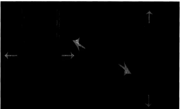
2. Armature lifts out of space, Material may deploy from subsequent orientation Another way for the armature to reconfigure is through vertical movements. Vertical movements allow the armature to completely lift out of the space to completely clear the floor to create a truly open and uninterrupted space. This complete clearing is a characteristic unique to this category of flexible armature. The following figure provides a summary of the three potential ways that armature can lift out of the space (Figure 12).
L, u ai atr (1) . I '4l l
I
Al
rt
AA,5% Sr-'z~~~~~~~~~~~~~~~CLtf3/
or &W 4 cu-AtW OIL fVdL~ 41C Li i
EicH4r -AFigure 12. Three Potential Methods of Lifting Columns out of Space: 1. Straight Up, 2. Rotate Up with Vertical Deployment, 3. Rotate Up with Horizontal Deployment
Each of these lifting methods creates a partitioning element through the
deployment of material between two columns; material is deployed when the columns are
/
(3)
I
.. ... CJC- .---- _ --t I I.
(2)s
pulled apart. In addition, these methods also include a horizontally deploying capability as shown in the "Double Column Extension Method."
The first method lifts the armature directly out of the space without changing orientation. The advantage of this method will become more apparent through subsequent discussion on the disadvantages of the remaining two methods. The
drawback with this design is the space needed to store these columns once they have been withdrawn upwards; this space will need to be as tall as the space below to completely remove the columns thus creating an storage space above with little flexibility and usefulness.
For the second and third methods, the armature is extracted from the space by rotating the armature upwards. The exact direction of the rotation differentiates the second design from the third. In the second design, one column ends below the other allowing for vertical deployment of material much like a window shade (Figure 13).
Figure 13. Example: Vertically Deploying Window Shade
In the third design, the pair of columns is rotated to the side and so that the columns end up side by side. When the columns are separated and the material is deployed, the material forms a horizontal plane to create a canopy or ceiling. This horizontal deployment creates a form not discussed in the performance specifications. Although not mentioned earlier, this design may allow this reprogrammable building edge to extend beyond the defined limits if the columns can extend out of the space to essentially create an awning. An awning provides a partially shaded or sheltered space for outdoor activities and sitting spaces.
5.2 Design Evaluation
To evaluate each design proposal, the design concept was first assessed as a whole with some reference to the relative strengths and weakness of the other designs. Then, each design that still merited consideration was assessed against the relevant
performance specifications. Through this process, the most promising architectural design emerged for further exploration and detailing and a subsequent mechanical design process. This section gives a brief evaluation of the most promising architectural
design and the subsequent section discusses the evaluation of that design. Inherent in its conceptual design, a system with flexible armature naturally increases the flexibility of a space over its stationary counterparts. This proposal is really a proposal to build a system that can achieve other models that are based on straight edge walls. Any of the
configurations possible with the relevant designs will also be possible with this system. This characteristic alone is sufficient to justify proceeding to the next stage of design.
5.3 Most Promising Design
Through the evaluation process, the planning thesis has determined that the most promising design is the system of flexible armature comprised of columns and deployable material. A general framework of function was defined in greater detail before
proceeding to the mechanical design. This framework included how the columns will function, how they will be clustered, and the number of columns. The details of function will be elaborated in this section, while clustering and column count explanations are
included in Appendix G.
Column function is dependent on how the material is deployed, retracted and stored. There were four potential solutions. The first solution involves a single column with material extending outward by some mechanism in one or two directions. The
second solution uses a pair of columns with material stretched between them; the material stored within the columns is deployed as the columns are pulled away from one another. Similar to the prior solution, the third solution employs a cluster of three columns with two segments of material stretched between the three, or in other words, a center column with material deployed as the other two columns are pulled away. The final solution is also based on the second solution, but with an added hinge at the top to lift the columns out of the space to both clear the space and to allow vertical or horizontal deployment. The following table summarizes these column systems.
Table 2: Four Potential Column Systems for Wall Deployment
Extending Walls 2-Column, Material 3-Column, 2-Direction Hinged Columns Stretched Between Material Deployment
To select a column system for further design, the feasibility and drawbacks of each of these column and material deployment designs are evaluated. As noted before, the largest concern of the extending wall system is whether the mechanisms for extending the wall can be strong enough. The 2-column design is promising as long as material deployment is actuated by the separation of the columns rather than an extending
to be sturdier with two firmly fixed material holders. The 3-column design is similar to the 2-column design and is equally as promising; the only drawback is the increased number of columns that may increase the density of columns and size of column systems resulting in crowding of the building-edge space. Finally, the hinged column is based on the promising 2-column design, but the hinging action is difficult to achieve cleanly; the following diagram demonstrates the obstacles for a hinged system (Figure 14).
vea
wt+rd t
-
act dme
ch
OWL
c*tb~
a
J40J
A&4-x
fm-U
Ac -
}C
iM t iF*i
oYifiut kh '
fr* Ih& O lot 'of ej=L,,
finch III
00"Ie.
Nola OC 4c 'r n" u
0
--0 xrac
14apa4o*
H
tr.AaWVf*&'
P" S*LI I; s fVgrw+Votia MMOA-4'Figure 14. Obstacles in Design Exploration for Hinged Column Material Deployment
These diagrams illustrate the design process through which the hinged column was eliminated from consideration. The design evolved through consideration of the functional requirements of a hinged pair of columns. Horizontal deployment was determined feasible using an existing track system, but horizontal deployment where tracks already exist will for the most part deploy material below a ceiling, a pointless effort. Exploration of vertical deployment revealed the complexity of mechanical design necessary for realizing this concept. Consequently, this investigation confirmed that the hinged column would be unsuitable and that a 2-column material deployment system would best serve this building-edge system.
_Z44"
. -__