Publisher’s version / Version de l'éditeur:
Questions? Contact the NRC Publications Archive team at
[email protected]. If you wish to email the authors directly, please see the first page of the publication for their contact information.
https://publications-cnrc.canada.ca/fra/droits
L’accès à ce site Web et l’utilisation de son contenu sont assujettis aux conditions présentées dans le site LISEZ CES CONDITIONS ATTENTIVEMENT AVANT D’UTILISER CE SITE WEB.
Student Report; no. SR-2009-03, 2009-01-01
READ THESE TERMS AND CONDITIONS CAREFULLY BEFORE USING THIS WEBSITE. https://nrc-publications.canada.ca/eng/copyright
NRC Publications Archive Record / Notice des Archives des publications du CNRC :
https://nrc-publications.canada.ca/eng/view/object/?id=adefa4d8-aedb-4d4f-9245-3436f0d38593 https://publications-cnrc.canada.ca/fra/voir/objet/?id=adefa4d8-aedb-4d4f-9245-3436f0d38593
NRC Publications Archive
Archives des publications du CNRC
For the publisher’s version, please access the DOI link below./ Pour consulter la version de l’éditeur, utilisez le lien DOI ci-dessous.
https://doi.org/10.4224/18227304
Access and use of this website and the material on it are subject to the Terms and Conditions set forth at The Planar Motion Mechanism; IOT's Latest Model
National Research Council Canada Institute for Ocean Technology Conseil national de recherches Canada Institut des technologies oc ´eaniques
SR-2009-03
Student Report
The Planar Motion Mechanism; IOT's Latest Model.
Wroblewski, L.
Wroblewski, L., 2009. The Planar Motion Mechanism; IOT's Latest Model. St. John's, NL : NRC Institute for Ocean Technology. Student Report, SR-2009-03.
DOCUMENTATION PAGE
REPORT NUMBER
SR-2009-03
NRC REPORT NUMBER DATE
April 2009
REPORT SECURITY CLASSIFICATION
Unclassified
DISTRIBUTION
Unlimited
TITLE
THE PLANAR MOTION MECHANISM; IOT’S LATEST MODEL
AUTHOR(S)
Leah K. Wroblewski
CORPORATE AUTHOR(S)/PERFORMING AGENCY(S)
Institute for Ocean Technology – National Research Council
PUBLICATION
SPONSORING AGENCY(S)
Institute for Ocean Technology – National Research Council
IOT PROJECT NUMBER NRC FILE NUMBER KEY WORDS
Planar Motion Mechanism, model tests, ice tank
PAGES 28 FIGS. 22 TABLES SUMMARY
This report will give a detailed description on what a Planar Motion Mechanism is, what it does and what kind of testing it is used for. The report will give details on the ice tank testing facility,
background information on the planar motion mechanism, details of the new version as well as a description of the tests that were conducted earlier this year to determine its working ability.
ADDRESS National Research Council
Institute for Ocean Technology Arctic Avenue, P. O. Box 12093 St. John's, NL A1B 3T5
National Research Council Conseil national de recherches Canada Canada Institute for Ocean Institut des technologies
Technology océaniques
The Planar Motion Mechanism; IOT’S Latest Model
SR-2009-03Leah K. Wroblewski
SUMMARY
This report details the Planar Motion Mechanism, a special device that enhances the ability to test models of ships and offshore structures in the facilities of the National Research Council’s Institute of Ocean Technology. The mechanism has been used in IOT’s ice tank in both open water and ice testing in order to
dynamically simulate real life environments for the models being tested. From testing that has been completed using this mechanism, significant data can be obtained that will prove to be critical when constructing the actual vessel and for producing numerical models.
The report itself provides background information on the PMM and general topics on model ship testing. This includes details on the six degrees of freedom of a floating body, details of harmonic testing, as well as how the PMM is significant for this type of testing. The report also covers information on why testing should be done for vessels and offshore structures.
In addition, the report will also discuss recent testing that was carried out on the newest version of the PMM. Several figures are included which show how these tests were carried out.
Lastly, a conclusion that summarizes what has been presented in the report will be included.
Table of Contents
1.0 Introduction………..1
2.0 Institute of Ocean Technology………..1
2.1 The Ice Tank Testing Facility………2
3.0 Offshore Structures and Ships that Encounter Ice………5
4.0 Ship Motions………...7
5.0 Planar Motion Mechanism………9
5.1 Harmonic Tests………..9
5.2 Set-up………10
5.3 Types of Testing………..13
6.0 Testing With the Latest Model………...15
7.0 Specifications and Improvements to the PMM………22
8.0 Conclusion and Recommendations………..………24
9.0 References………25
List of Figures
Figure 1: Ice Tank layout.………..3
Figure 2: Diagrams of the Tow Carriage and the Service Carriage……….4
Figure 3: Front view of the tow carriage from the north side of the tank……….…4
Figure 4: (From left to right) Onshore Platform, Fixed Platform, Jack-up Rig, Semi-Submersible, Frill Ship, and Tension Leg Platform……….6
Figure 5: Sunkar drilling barge in winter surrounded by ice rubble….……….6
Figure 6: The Explorer; one example of the devastating effects of ice………..…..7
Figure 7: The Six Degrees of Freedom……….8
Figure 8: The sway-sub carriage about to be mounted underneath the tow carriage………...……….11
Figure 9: Dynamometer that attaches to the Terry Fox model………11
Figure 10: The Terry Fox with the dynamometer installed within ………..12
Figure 11: Rear view of the PMM with Terry Fox model attached……….13
Figure 12: Movements with the PMM ………14
Figure 13: The Terry Fox as it starts to proceed down the tank in the initial ice sheet test in a path controlled by the PMM………...……….16
Figure 14: The Terry Fox as it starts to proceed down the tank in the initial ice sheet test……….17
Figure 15: The rear view of the model …...………17
Figure 16: The path made in the ice.………..…18
Figure 18: The model during testing with pack ice ………..19 Figure 19: Model during testing..………..……...20 Figure 20: View of the pack ice from the top of the service carriage prior to the
initial Test………20 Figure 21: The Terry Fox attached to the PMM after the initial pack ice test…. 21 Figure 22: View of the ice tank after the ice sheet had been broken up into pack ice….………21
1.0 INTRODUCTION
Model ship testing has always been of utmost importance in the marine industry. The Institute of Ocean Technology conducts many tests of both offshore
structures and marine vessels using its world class testing facilities and advanced technology. These facilities and technologies allow the institute to simulate environmental conditions and movements of the floating body in order to obtain valuable information for clients from all around the world. One of these advanced technologies is the Planar Motion Mechanism (PMM). The PMM is a very significant piece of equipment due to its ability to move the attached model in a variety of exact manoeuvres simulating life-like conditions. Several versions of PMMs have been in existence. In winter of this year, a new upgrade has been constructed and was tested in the ice tank testing facility at IOT. The following report describes this testing and gives background information regarding the theory and motions behind the PMM.
2.0 INSTITUTE OF OCEAN TECHNOLOGY
The National Research Council of Canada is a national research and
development organization. Starting in 1916, the institute currently has more than 20 programs and departments throughout the country, including the Institute of Ocean Technology (IOT) located in St. John’s, NL (3). IOT was established in 1985 and is known throughout the world for conducting research using its world class testing facilities. The institute is well known for its ability to simulate real
world environments and develop new technologies in order to provide data that is significant to the marine industry. Highly skilled technologists, designers, and engineers conduct experiments using the many unique testing facilities at IOT which include The Offshore Engineering Basin, Tow Tank, Ice Tank, Cold
Rooms, and Cavitation Tunnel. In addition, the institute has special technologies that enhance these facilities, which include a yacht dynamometer, the marine dynamic test facility, and the planar motion mechanism (2).
2.1 The Ice Tank Testing Facility
The Ice Tank, also known as the refrigerated model basin, is the largest of its kind in the world and is used to simulate Arctic environments for testing purposes (11). The 90 m long tank allows for 76m long ice sheets to be created of various thickness. The 12m width and 3m depth of the tank allows for limited
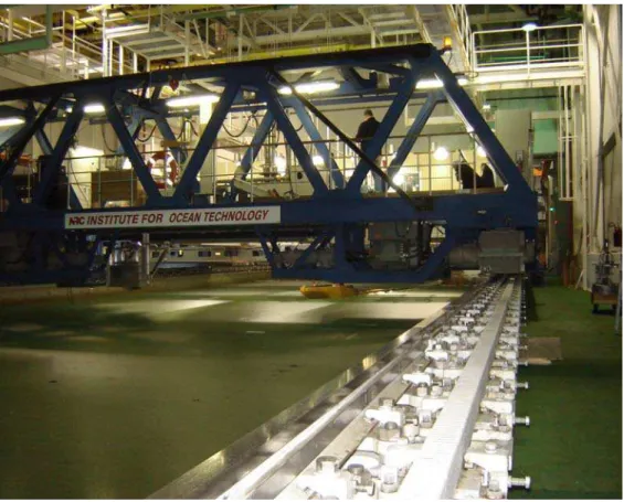
manoeuvrability of the models being tested, but still allows for larger models to be either self-propelled, moored or towed along the tank (4). The basin contains a 15m long vicinity called the trim dock or set-up area, which is used to prepare the model being tested. This area is separated from the rest of the tank by a large door that acts as a thermal barrier. At the other end of the tank is a large melt pit that has a sloped ramp leading to it. This pit has an insulated cover at the top that allows for ice kept within to melt while another ice sheet is being grown above (11). Both the set-up area and the melt pit can be seen in Figure 1, a diagram showing the layout of the tank. The tank itself rests on four concrete columns which allow thermal expansion to occur with changing temperatures.
Held in a 105m long, 18m wide, 10m high space, the walls and ceiling are made of materials that use special techniques to reduce air leakage in from the outside. Several underwater cameras surround the model placed in the test frame of the tow carriage (as seen in Figure 3), being placed both on the underwater carriage and above the water (11). Models are of various sizes; for ships they are 2-12m in length and 0.5-4m for offshore structures (4). These models are attached to the tow carriage (Figure 2) and rest on the test frame which can be adjusted to properly fit the model. The ice tank allows for testing of ship resistance, ship self-propulsion, manoeuvring in ice, and the measurement of ice forces on moored and fixed structures while in a simulated ocean environment (4).
Fig. 1 Ice tank layout (Picture adapted from http://iot-ito.nrc-cnrc.gc.ca/facilities/it_e.html)
Fig. 2 Diagrams of the tow carriage and the service carriage (Picture adapted from http://iot-ito.nrc-cnrc.gc.ca/facilities/it_e.html)
3.0 OFFSHORE STRUCTURES AND SHIPS THAT ENCOUNTER ICE
The oil and gas industry is one example of an industry that heavily relies on ships and offshore structures year round, thus ice is a major obstacle that is
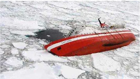
encountered. Over 4,000 production facilities are currently operating on the Outer Continental Shelf causing corrosion, fatigue, and damage caused by ice and ice floes to be of major concern (5). Such activity requires testing to be done in a simulated environment to determine the ability of a vessel or structure to deal with such issues. As can be seen in Figure 4, various types of structures are already in operation off the shores of North America. Dangerous external loads can be put on these structures by heavy amounts of ice. Because ice in the ocean varies in strength, thickness, size, drift speed, and concentration, measuring the amount of load that will be applied is very difficult (6). With the need to simulate complex loads imposed by ice (such as that in Figure 5), experiments with an actual physical model have been proven to be the best method for assessing how ships and structures will interact with an ice
environment (14). One can see how important this knowledge is by seeing what happened to The Explorer cruise ship when it came into contact with ice (Figure 6).
.
Fig. 4 (From left to right): Onshore platform, fixed platform, jack-up rig, semi-submersible, drill ship, and tension leg platform (image from
http://www.mms.gov/tarprojectcategories/structur.htm)
Fig. 5 Sunkar drilling barge in winter surrounded by ice rubble (image from http://www.ogp.org.uk/pubs/4004.pdf)
Fig. 6 The Explorer; one example of the devastating effects of ice (image adapted from
http://www.dailymail.co.uk/news/article-495918/Titanic-terror-Britons-saved-Antarctic-rescue-cruise-ship-struck-iceberg.html)
4.0 SHIP MOTIONS
There are six degrees of freedom that are used to describe the motion of a ship or floating structure (7): •Yaw •Sway •Roll •Pitch •Heave •Surge
Fig. 7 The Six Degrees of Freedom
The direction of each degree uses the right hand coordinate system where z points down, sway and yaw are positive, and surge is positive in the direction of motion (13). As shown in Figure 7, yaw often occurs from a sudden steering manoeuvre and is measured as rotation along the vertical (z axis). Sway is defined as sideways motion measured as the boat moves back and forth along the y-axis. Rotation about the longitudinal (x-axis) is known as roll and rotation along the transverse (y-axis) is called pitch. Heave occurs when the entire vessel moves up and down (vertical motion) along the z-axis and when the boat moves along the x-axis (longitudinal motion provided by propulsive motion) surge occurs (7).
5.0 PLANAR MOTION MECHANISM
Model tests are the most effective way of assessing a ship’s manoeuvrability in an ocean environment. Ship model tests are done to determine numerical simulation data including hydrodynamic coefficients that represent ship motions in the form of a mathematical model (12). In order for these to be successful, the model itself has to closely replicate both the geometric and dynamic conditions of the ship and it’s operations (14).
The Planar Motion Mechanism (PMM) is a special device that is used in testing where models need to be manoeuvred through ice or open water (1) and is a significant component of IOT’s testing equipment. This device is especially important for providing numerical data for situations where ships and ice come into contact with each other. The PMM is able to simulate ocean environments and motions of a ship that may occur in real life. The movements of the PMM are controlled by computer programs which pre-program the exact patterns,
moments, force, and motion surrounding the model which are later recorded in detail, making the device excellent for specific testing (13).
5.1 Harmonic Tests
Many tests exist for model ships. These include stationary straight-line tests, stationary circulation tests, harmonic tests, pure sway, pure yaw, pure yaw with rudder deflection, and pure yaw with drift (9). Harmonic tests are those that
require a Planar Motion Mechanism to complete since a number of parameters go into setting up these tests including sway and yaw characteristics. Because the model will be in constant motion in a number of directions for such a test, parameters set are often restricted by the size of the tank and the means by which the ships motion is provided (9). The planar motion mechanism is
extremely significant for these tests since forward speed, propeller rate, type of propulsion, and a pre-programmed path are able to be set by the PMM and the carriage of which it is attached (15).
5.2 Set-up
The outer frame of the PMM is attached to the bottom of the main tow carriage in the tank, providing forward movement. This is where the sway sub-carriage (Figure 8) is connected. The yaw assembly (allowing for yaw movement) is then connected to the sway sub-carriage. The PMM allows the model to move along the y-axis (parallel to the tow carriage) and to rotate along the z-axis, besides movement along the x-axis, which is provided by the carriage itself (12). One aspect of the PMM that makes it so unique is it’s ability to control the yaw and sway axes of the model. The model is mounted onto a special dynamometer (Figure 9) that is attached to the PMM. This is used to measure forces such as torque and rotational speed of the model as well as components of the 6 degrees of freedom (15). A computer control system manages the sway and yaw motors and complex motion is programmed into the system. Before the tests are carried
out, the software of the PMM ensures rates assigned for the parameters are able to safely occur. During execution, the module loads data files, sending
information to the motors controlling the sway and yaw motions. Once the files are transferred, the program takes control (13). Figures 10 and 11 show views of the Terry Fox model attached to the PMM.
Fig. 9 Dynamometer that attaches to the Terry Fox model
Fig. 11 Rear view of the PMM with Terry Fox model attached
5.3 Types of Testing
The most common tests that are conducted with the PMM are rudder and yaw sweeps, pure yaw and sway tests (1). The PMM’s controlled sway motions, and measured sway and surge forces along with yaw moments allow the model to move in many different directions (12). The four standard motion test types conducted by the PMM are static drift, pure sway, pure yaw and pure yaw with drift (13). A diagram showing this motion can be seen in Figure 12. Static drift occurs when the model being tested is yawed at a specific predetermined angle and where the forward direction of movement is fixed. Pure sway is a test that involves the model being held at a yaw angle of zero and is swayed along the y-axis with a particular period and amplitude. A pure yaw test involves specific yaw
motion to that at which the model is travelling in a direction that is always tangent to the curve of its motion. This test exposes the hull to a number of headings at different advancing speeds (10). Finally, a test where the model’s drift angle is added to the yawing angle and that has the model drifting relative to an angle of the pure yawing motion is referred to as pure yaw with drift (13). (Yaw angle refers to the angle between the ship’s heading and a reference point, drift angle is the angle made between the heading of the vessel and the path taken [7].)
Static drift
Pure Sway
Pure Yaw
Pure Yaw with Drift X+ Y+
#
M .$
Fig. 12 Movements with the PMM (image adapted from Planar Motion Mechanism Controller Guide, Oceanic Consulting Corporation, 2005)
6.0 TESTING WITH THE LATEST MODEL
During the month of January a new model of the Planar Motion Mechanism arrived at the Institute of Ocean Technology. This model had been in the works for quite some time and was constructed in hopes of fixing problems that had been discovered with the old model in 2005. The PMM was specially designed for the facilities at IOT by Cussons Technology, a leading manufacturing company of industrial testing equipment based in the United Kingdom. Several tests were conducted using a model of the Terry Fox Icebreaker both with level ice (the original and unbroken ice sheet) and pack ice (level ice broken up into pieces of a specific size) of 40mm thickness, corresponding to 800 mm full scale level ice in (typically in the range of first year ice). This ice was prepared in the ice tank at IOT. The ice tank allows for an air bubbler system to create ice of particular density, which allows for ship and ice interactions to be modeled
effectively. The tank is kept at particular temperatures (usually around 0 while the tests are being completed), and shear strength, flexural strength, compression tests, and density tests are performed on the ice throughout testing (14). Pack ice was created by breaking apart the level ice using the platforms of the service carriage in the ice tank and also by cutting the ice vertically. Ice floes were of a particular square shape in order to model actual ice conditions. Several
photographs were taken of the pack ice using a birds eye view from the top of the service carriage prior to each experiment to determine pack ice concentration. As shown in Figures 12-17 the first test was conducted with a single flat ice sheet. One can see from the path that the Terry Fox model left in the ice that the model travelled along the y-axis with the boat rotating in synchronization to create a sinusoidal path through the ice. This path was pre-programmed into the PMM before the test was completed.
Fig. 13 The Terry Fox as it starts to proceed down the tank in the initial ice sheet test in a path controlled by the PMM
Fig. 14 The Terry Fox as it starts to proceed down the tank in the initial ice sheet Test
Fig. 16 The path made in the ice
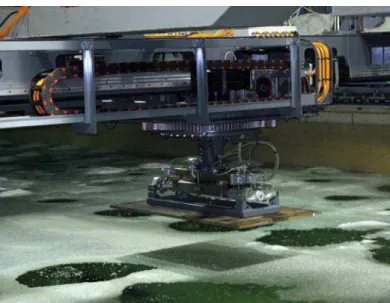
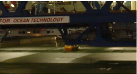
Figures 18-22 show the tests that were conducted with pack ice. During these two tests the Terry Fox model moved along the tank in a pure sway path; the ship moved along the y-axis as it was propelled by the carriage in the forward direction along the x-axis. Figure 18 and 19 were taken while the model was in motion.
Fig. 19 Model during testing
Fig. 20 View of the pack ice from the top of the service carriage prior to the initial test
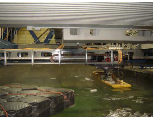
Fig. 21 The Terry Fox attached to the PMM after the initial pack ice test
Fig. 22 View of the ice tank after the ice sheet had been broken up into pack ice
7.0 SPECIFICATIONS AND IMPROVEMENTS TO THE PMM
With the creation of the latest version of the PMM, several changes had been made in order to improve and correct errors that were present in the previous model (15). For example, many issues were present within the configuration of the PMM’s control system. A number of other improvements had been made since the use of the last PMM:
1. The 2005 model had breakout boxes that were in need of repair. The newer version has a breakout box with 12 uncommitted connections that can be used by sensors and signals if needed for future use.
2. Proximity switches for travel limits provided with the new version ensure that the PMM will stay within its range of motion so the model will not impact the tank walls during testing.
3. Mounting arrangements for the tow carriage are now improved with the new version, wooden spacers have been placed at the ends of the PMM frame and C-clamps are used when attaching the frame. In addition, mounting plates are now permanently welded to the sides of PMM and to the tow carriage test frame. 4. A self-contained data acquisition computer is used for calibration
5. The cabinet containing the controls for the PMM is placed outside the control room; inside the control room is a laptop taking up little space and a small console that contains a joystick and a stop button in case of an emergency.
6. The new PMM now has a closed loop control and a separate transducer that is able to detect sway and yaw positions, an improvement from the last model.
In addition to these solutions, improvements were made to the stiffness of the system, control and precision of motion, and improvements to the load
8.0 CONCLUSION AND RECOMMENDATIONS:
The recent tests that were conducted with the PMM in IOT’s world class ice tank show how the path of a ship as it travels through ice can be simulated in a
controlled environment. Harmonic testing done with the PMM display how critical tests like this are of utmost importance for the safety and sustainability of ships and offshore structures that come into contact with ice. By using the PMM,
elements such as load forces, moments and measurements of the six degrees of freedom for a model ship can be measured and this mathematical data allows for conclusions to be drawn that are crucial for the marine industry. The testing conducted in February of this year was successful in showing differences between the old and new PMM and how several improvements were made. Nevertheless, more testing is to be completed with this model and will occur in the Ice Tank throughout the year.
9.0 REFERENCES:
1. (2002) Oceanic Consulting Corporation, Planar Motion Mechanism
Retrieved March 13, 2009 from:
http://www.oceaniccorp.com/EquipmentDetails.asp?id=2
2. (2005) National Research Council Canada, Institute of Ocean Technology,
About Us
Retrieved March 15, 2009
http://iot-ito.nrc-cnrc.gc.ca/about_e.html
3. (2005) National Research Council Canada, About Us
Retrieved March 15, 2009
http://www.nrc-cnrc.gc.ca/aboutUs/index_e.html
4.0 (2005) National Research Council Canada, Ice Tank Retrieved April 1, 2009
5.0 (2009) Offshore Energy & Minerals Management. Offshore Structures.
Retrieved March 13, 2009 from:
http://www.mms.gov/tarprojectcategories/structur.htm
6.0 Bol’shev, A.S., Shkinek, K.N., Frolov, S.A., Uvarova, E.V. (2000). Hydro Technical Construction. Simulating Likely Ice Loading on continental-Shelf
Structures, 34, pp 614
7.0 Britannica Online Encyclopedia. Ship Motions in Response to the Sea
Retrieved March 3, 2009 from:
http://www.britannica.com/EBchecked/topic/540904/ship/64201/Ship-motions-in-response-to-the-sea#ref528245
8.0 International Association of Oil and Gas Producers. International Standards
Bulletin.
Retrieved, March 5, 2009 from:
9.0 International Towing Tank Conference. (2002) Testing and Extrapolation Methods Manoeuvrability Captive Model Test Procedure, pp 6-26
10.0 John E. W. (2002). Journal of Offshore Mechanics and Arctic Engineering.
Comparing Different Test Procedures to Determine the Coefficients of the Manoeuvring Model for an FPS0, 212-213
11.0 Jones, S.J. (1986). Proceedings of the 21st American Towing Tank Conference: Canada’s New Ice Tank.
Washington, D.C., U.S.A. National Academy Press
12.0 Lau, Michael, Liu, Jian Cheng, Derradji-Aouat, Ahmend, Williams, F. Mary. (2004) Preliminary Results of Ship Manoeuvring in Ice Experiments Using a
Planar Motion Mechanism. pp1-3
13.0 Oceanic Consulting Corporation. (2005). Planar Motion Mechanism; Control
Software User Guide, Control Software Documentation, Control Software Listing, Compumotor Z600 Series Software Reference, pp1-3, 18-19
14.0 Shi, Yu. (2002) Model Test Data Analysis of Ship Manoeuvrability in Ice .pp
15-24, 56-61
15.0 IOT PMM archived files and photos
10.0 ACKNOWLEDGEMENTS:
There are many people I wish to thank for helping me create this report. First of all I would like to acknowledge Brian Hill of the Institute of Ocean Technology. I would also like to thank Chris Meadus, Steven Keats and Austin Bugden for helping me obtain information about the PMM and for answering the many questions I had about experiments in the ice tank. I would also like to thank Michael Lau and Paul Thorburn for their help with obtaining data from the testing that occurred in January/February of this year on the new PMM model.