Bioinspired Mineralization in Hydrogels for
Sustainable Materials Processing
byAbigail U. Regitsky
B.S. Materials Science and Engineering
Georgia Institute of Technology, 2013
Submitted to the Department of Materials Science and Engineering
in partial fulfillment of the requirements for the degree of
Doctor of Philosophy in Materials Science and Engineering
at theMASSACHUSETTS INSTITUTE OF TECHNOLOGY
September 2018
© 2018 Massachusetts Institute of Technology. All rights reserved. Signature of Author: _____________________________________________________________ Department of Materials Science and Engineering August 6, 2018 Certified by: ___________________________________________________________________ Niels Holten-Andersen Associate Professor Thesis Supervisor Accepted by: ___________________________________________________________________ Donald R. Sadoway Chairman, Departmental Committee on Graduate Studies
Bioinspired Mineralization in Hydrogels for Sustainable
Materials Processing
byAbigail U. Regitsky
Submitted to the Department of Materials Science and Engineering on August 6, 2018 in partial fulfillment of the requirements for the degree of Doctor of Philosophy in Materials Science and EngineeringAbstract
Biominerals have been widely studied due to their unique mechanical properties, afforded by their inorganic-organic composite structure and well-controlled growth in macromolecular environments. More recently, growing concerns over climate change and environmental sustainability and the emerging relevance of green chemistry make biomineralization an even more attractive process to study. In this thesis, we focus on the earlier stages of mineral nucleation and growth, where the organic, hydrogel-like matrix dominates the bulk of the material and the mineral is distributed throughout the matrix as nano- and/or microparticles. The phase, morphology, and size of the particles can be controlled using the choice of the hydrogel, functional moieties on the gel polymer backbone or ends, and soluble additives. Depending on the choice of organic matrix and inorganic mineral, the matrix can be dissolved to leave highly uniform particles with tailored properties for a variety of industrial applications, or the matrix can be left intact, creating a hydrogel-mineral composite with improved mechanical properties through organic-inorganic interfacial interactions or additional functionality, such as magnetic properties. In particular, we studied a gelatin-calcium carbonate mineralization system and demonstrated the use of rheology as a mechanoscopic characterization technique for monitoring mineral growth in hydrogels. We also investigated mineralization in metal-coordinate hydrogels, specifically magnetite in Fe-catechol crosslinked gels. We showed that magnetite mineralization occurs at the network crosslinks, leading to mechanical reinforcement of the hydrogel while introducing magnetic properties to the material. Finally, we used tannic acid to modify the growth of calcium carbonate particles, which we employed as green additives for reducing the friction and wear of lubricants. Thesis Supervisor: Niels Holten-Andersen Title: Associate Professor
Acknowledgements
My deepest gratitude goes to my advisor, Niels Holten-Andersen. I am incredibly thankful for his guidance and encouragement throughout my PhD, which were always delivered with a smile. His passion for scientific discovery and excitement for new ideas made research that could sometimes feel mundane truly fun and rewarding. I really appreciate how much Niels cares about his students, in both their scientific and their personal development. He gave me the freedom to explore not only my own research interests but also my personal and professional interests in sustainability and policy, which has empowered me to embark on a career path that a few years ago was only a dream. I would also like to thank the members of my committee: Professors Alfredo Alexander-Katz, Carl Thompson, and Krystyn Van Vliet. The questions and insights they provided have only made this a better thesis. Throughout my research, I had the pleasure of collaborating with many people. First, I am extremely grateful to have had the opportunity to co-author a paper with Sungjin Kim. I have really enjoyed our conversations and experimental trials in figuring out our project together. For this and other projects, I would also like to acknowledge Jake Song and Dr. Bavand Keshavarz, as well as Professor Gareth McKinley, who has been like a second advisor to me. I would also like to thank all the past and present members of the Laboratory for Bioinspired Interfaces for always being willing to answer my questions and discuss new ideas and for not taking themselves too seriously and generally being great people.Although I came to MIT for academics, in hindsight, I have realized how fortunate I am to have chosen a grad school with so many extracurricular activities and student groups, which have given me remarkable opportunities to serve my community and to hone my leadership skills. I am particularly thankful for the MIT Graduate Student Council Sustainability Subcommittee and External Affairs Board, the MIT Waste Alliance, and the MIT Science Policy Initiative and all of the students and staff with whom I have worked. On a personal note, I would like to thank my friends at MIT, especially my DMSE classmates. From quals study sessions to board game nights, I would not have survived MIT without them. I would also like to acknowledge my family: my parents, Han and Tintin, who gave me opportunities from a young age to foster my scientific curiosity and have always pushed and supported me in all my endeavors and my parents-in-law, Jon and Stacy, for welcoming me into their family and for their constant support. Above all, I am grateful for my husband, Ross, whose unconditional love and support made this journey possible and whose Adobe Illustrator skills adorn several pages of this thesis. Lastly, I would like to acknowledge the sources of financial support that not only funded but also helped guide my PhD research: BP and the MIT Energy Initiative, for the DMSE/BP Fellowship and for providing opportunities to discuss my research interests, which led to some of my initial project ideas; Interlub S.A. de C.V., particularly Roberto Iberri and Susy Ferreira, for funding and for a rewarding industrial collaboration; the Martin Foundation and the MIT Environmental Solutions Initiative, for the Martin Fellowship for Sustainability and for programming and events to create a community of fellows; the MRSEC Program of the National Science Foundation under award number DMR – 1419807; and the Office of Naval Research under the Young Investigators Program Grant ONR.N00014-15-1-2763.
Contents
Introduction
11
Background
15
2.1 Calcium Carbonate Biominerals ... 16
2.2 Magnetite Biominerals ... 19
2.3 General Principles of Biomineralization ... 21
2.4 Nucleation and Growth Pathways ... 23
2.4.1 Classical Nucleation Theory ... 24 2.4.2 Non-Classical Theories—Precursors to Nucleation ... 252.5 Hydrogel Mineralization ... 26
2.5.1 Gelatin Hydrogels ... 28 2.5.2 Metal-Coordinate Hydrogels ... 282.6 Oscillatory Rheology ... 29
2.7 Sustainable Materials Processing & Applications ... 31
2.7.1 Green Chemistry & Sustainable Engineering ... 31 2.7.2 Mineral Carbonation ... 32 2.7.3 Hydrogel Composites ... 33Rheology as a Mechanoscopic Method to Monitor Mineralization in
Hydrogels
35
3.1 Introduction ... 35
3.2 Results & Discussion ... 38
3.2.1 Mineralized CaCO3 Characterization ... 38 3.2.2 Rheological Characterization ... 40 3.2.3 In Situ Mineralization ... 453.3 Conclusions ... 49
3.4 Experimental Methods ... 50
In Situ Mechanical Reinforcement of Polymer Hydrogels via Metal-coordinated Mineralization
53
4.1 Introduction ... 53
4.2 Results & Discussion ... 54
4.3 Conclusions ... 68
4.4 Experimental Methods ... 69
Tannic Acid-Modified Calcium Carbonate Particles as Sustainable
Lubricant Additives
75
5.1 Introduction ... 75
5.2 Results & Discussion ... 76
5.2.1 Characterization of CaCO3 particles ... 76 5.2.2 Friction reduction ... 78 5.2.3 Wear reduction ... 815.2.4 Effects of tannic acid ... 83
5.3 Conclusions ... 84
5.4 Materials and Methods ... 85
Conclusions & Outlook
87
6.1 Summary ... 87
6.2 Future Opportunities ... 88
Chapter 1
Introduction
Climate change is arguably one of the most pressing societal crises of our time. Global efforts by governments, companies, researchers, and individuals are underway to curb greenhouse gas (GHG) emissions in an attempt to keep global warming below 2 °C. Because the burning of fossil fuels for energy is responsible for a significant portion of these emissions, the majority of research and technological innovation that is conducted to address climate change deals with decarbonizing the world energy supply through alternative energy (and energy storage) technologies, such as solar photovoltaics, wind turbines, hydroelectric power, and hydrogen fuel cells. While tackling the energy challenge is critical and necessary, it is not sufficient to focus only on energy when endeavoring to create a more sustainable world. Another important, and often underrated, aspect to consider is the sustainability of the physical things that we make use of in everyday life, considering both the materials of which they are made and the processes by which they are made. Even if we had an endless supply of renewable energy, we could not and should not continue to build and produce material structures and goods with the disregard for sustainability and the environment that we often do now. Of course, this is not a new notion. The entire fields of green chemistry and engineering have developed over the last several decades to address the need for more sustainable products andprocesses.1,2 With the renewed interest in manufacturing, the concept of sustainable manufacturing has also begun to take root, complemented by the development of manufacturing technologies like additive manufacturing and bottom-up fabrication.3,4 In these disciplines, many are looking to Nature’s “manufacturing” processes for inspiration on how to produce things more sustainably and with unique properties. For the work in this thesis, we are largely inspired by the processes of biomineralization, whereby organisms form strong, tough inorganic-organic composites (such as shells, bones, and teeth) in a highly-controlled fashion under ambient conditions without harmful precursors or byproducts. By learning how Nature is able to grow these minerals, we can translate these inherently sustainable mechanisms into industrial manufacturing practices. In particular, we aim to help elucidate early biomineralization processes through novel mechanical characterization and to use these tools to more sustainably fabricate beneficial materials. In this thesis, we explore gelatin and metal-coordinate hydrogel mineralization systems at low particle fractions and use oscillatory rheology both to study how the minerals affect the mechanical properties of the hydrogel systems and to monitor the growth of the minerals in situ. We also exploit the ability of organic molecules to control mineral growth to develop sustainable additives for lubricant applications. In Chapter 2, we begin with background information included to give context for the remainder of the work covered in this thesis. It contains descriptions of calcium carbonate (CaCO3) and magnetite, biominerals which inspired the minerals grown in this work, and of the general biomineralization process, including the integral role of hydrogel-like matrices and mineral nucleation and growth theories. We also cover the basics of oscillatory rheology and of green chemistry, and we discuss the potential applications of hydrogel mineralization and hydrogel-mineral composites. Chapter 3 comprises our work with mineralizing CaCO3 in gelatin hydrogels and pioneering rheology as a mechanoscopic tool to monitor mineralization in situ, published as Ref. 132. In Chapter 4, we continue to use rheology to understand the mechanical reinforcement of magnetite in catechol-modified polyethylene glycol hydrogels when mineralized in situ at the gel crosslinking sites. We take a break from hydrogels in Chapter 5 to share an industrial
collaboration, where we used tannic acid to modify the growth of CaCO3 particles for enhancing lubricant performance. Each story is unique, but woven through them is the common thread of using chemistries and processes inspired by biomineralization to synthesize useful materials in a sustainable way.
Chapter 2
Background
Six hundred million years ago, organisms began incorporating inorganic elements into organized mineral components, a process known as biomineralization.5 The major types of biominerals synthesized by organisms today are calcium carbonates (CaCO3), phosphates, and oxalates; iron oxides and hydroxides; and silica. Many of these occur in different polymorphs and have a variety of functions, such as structural support, calcium and iron storage, and sensing.6,7 These biominerals are inorganic–organic composites formed in aqueous environments at physiological conditions, often with superior mechanical properties, such as higher toughness and ultimate tensile and compressive strength, compared to their purely inorganic counterparts.8 Thus, biominerals have been widely studied from biological, chemical, and materials science standpoints in order to better understand the mechanisms involved in their formation and to learn how to mimic these “green” mineralization processes in synthetic systems.9–12 One of the most well-known and studied examples of biomineralization is nacre, which has a brick and mortar composite structure of high aspect ratio tablets of aragonite (aCaCO3 polymorph) within a proteinaceous organic matrix.13 The organic matrix functions both as
a scaffold for nucleation and growth during crystallization and as a glue in the final composite structure.14 During mineralization, the organic matrix creates a hydrogel-like environment within which the aragonite tablets grow.15 In addition to nacre, other biominerals, such as
in hydrogel-like organic matrices. Thus, in vitro hydrogel networks have become a common method to experimentally study and mimic natural biomineralization systems.26–31
Because of the increased structure of the environment and solution confinement in pores, mineralization in gels varies greatly from that in solution. Classical nucleation theory does not account for the intricacies associated with gels, such as time-dependent chemical gradients and interactions with the gel network itself.32 It is also difficult to detect nuclei within gels,29 and
experiments are limited to basing nucleation times from when crystals can be visually observed instead of actual nuclei formation.30 Furthermore, recent studies have suggested that biomineralization may occur through non-classical nucleation and growth pathways, potentially involving amorphous precursors to nucleation.33–38 Hence, important pre-nucleation events may be entirely unnoticed in hydrogel systems using current characterization techniques. Rheology is a mechanical characterization tool commonly used to measure the properties of hydrogels and other soft, viscoelastic materials. Using rheology to study in vitro hydrogel mineralization schemes could provide a novel method to observe these early mineralization events.
2.1 Calcium Carbonate Biominerals
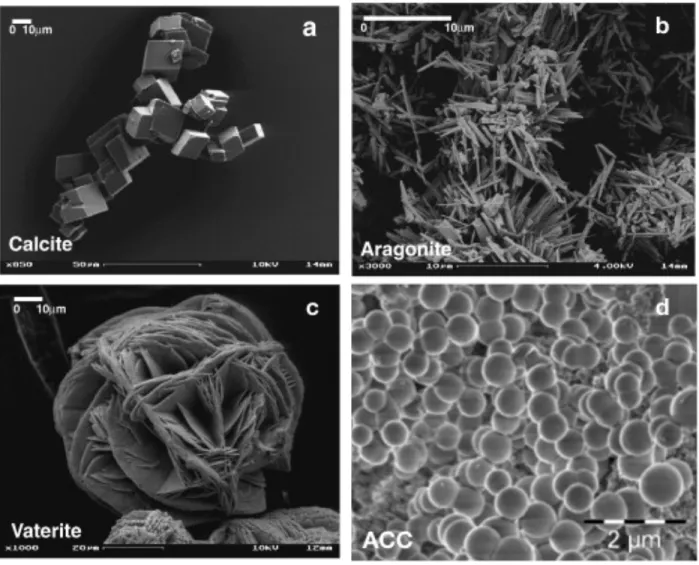
Calcium carbonate has four anhydrous mineral phases, in order of decreasing stability: calcite, aragonite, vaterite, and amorphous calcium carbonate (ACC), which has at least five variants.39 The most widely occurring polymorphs in biominerals are calcite and aragonite, while vaterite exists rarely in nature and ACC occurs largely as calcium storage sites.8 However, ACC has also been shown to play an important role in early mineralization of calcite and aragonite biominerals as a transient phase.36,40–43 Calcite has a hexagonal crystal structure and forms rhombohedral crystals,44 shown in Figure 2.1a, while aragonite is orthorhombic and commonly forms needle-like crystal aggregates,45 shown in Figure 2.1b. Vaterite is also hexagonal and typically forms fine fibrous crystals in spherulitic aggregates,46 shown in Figure 2.1c. It can sometimes be difficult to differentiate vaterite from ACC, which exists as amorphous spheres, shown in Figure 2.1d.41Figure 2.1 SEM images of CaCO3 polymorphs, showing different shapes and morphologies of the polymorphs. (a) Rhombohedral calcite, (b) needle-like aragonite, (c) vaterite spherulites, and (d) spherical ACC. Adapted from refs.41,47 Calcium carbonate biominerals are largely found in marine organisms, for which they often function as exoskeletons, such as shells.8 Corals, coccolithophores (unicellular algae), brachiopods, and mollusks are some of the organisms that utilize CaCO3 in their inorganic components.48 As mentioned above, nacre is a classic example of a CaCO 3 biomineral which composes part of most mollusk shells. The brick-like structure of nacre can be seen in Figure 2.2. The aragonite platelets are typically ~10 μm in diameter and ~0.5 μm thick, glued together by ~20 nm thick layers of organic matrix, which makes up only ~5wt% of the entire material.49 In addition to the nacreous layer, mollusk shells have an outer prismatic layer, also shown in Figure 2.2, which is generally composed of calcite but depending on species, can also be aragonite.48
The prismatic layer has high hardness for initial protection, while the nacreous layer has high toughness to resist crack propagation. Figure 2.2 (a) SEM image of a section of a mollusk shell, showing the structural and morphological differences in the nacreous and prismatic layers and (b) a higher magnification SEM image of nacre, detailing the brick and mortar-like tile arrangement. Adapted from refs.48,50 Although it constitutes a very small fraction of nacre, the organic matrix is key to the formation and structure of the overall composite. As shown in Figure 2.3a, prior to mineralization, the organism deposits a pre-formed matrix consisting of layers of β-chitin interspersed with a silk-like hydrogel.15 Within the hydrogel and along the chitin layers are aspartic acid-rich glycoproteins, depicted in Figure 2.3c, which are involved in controlling mineral nucleation and growth.51 Once mineralization is initiated, the aragonite tablets grow within the hydrogel region, shown in Figure 2.3b, with their c-axes aligned perpendicular to the tablet stacking direction and occlude some of the organic matrix into what becomes the thin glue layer.15
Figure 2.3 Depictions of the mineralization environment of nacre (a) before and (b) after mineralization has occurred. (c) A more detailed look at the pre-formed organic matrix components of nacre. Adapted from refs.15,51
2.2 Magnetite Biominerals
Magnetite is another common biomineral, often studied due to its magnetic properties. It is an iron oxide with the formula Fe3O4 and contains both divalent and trivalent iron in a face-centered cubic lattice.52 It is ferrimagnetic at room temperature, and the preferred direction of magnetization, or easy axis, is along the [1 1 1] cube diagonals.53 Magnetite biomineralization is primarily studied in magnetotactic bacteria and chitons, but it is also proposed to be involved in the magnetoreception of migratory/homing birds, honeybees, and some fish.54 The mineral components of magnetotactic bacteria are contained in magnetosomes, a magnetite nanoparticle enveloped in an organic vesicle.55 Some magnetotactic bacteria mineralize greigite (Fe3S4), but we will focus solely on magnetite in this thesis. The size and shape of magnetosomes is highly genetically regulated and varies between different strains of bacteria; however, each individual nanoparticle fits within a size range (35-80 nm) such that it remains a stable single magnetic domain. Within a bacterium, the magnetosomes are arranged along their easy axis to form a chain (see Figure 2.4a), which is hypothesized to facilitate magnetotaxis, allowing the bacterium to align with Earth’s magnetic field lines.56 Because of the fine control ofa
b
c
nanoparticle size, shape, composition, and magnetic properties afforded through magnetosome biomineralization, many studies have focused on mimicking this biomineralization scheme for magnetic nanoparticle applications.57–59 Figure 2.4 (a) Transmission electron microscopy image of magnetotactic bacteria (scale bar 1 μm) and (b) optical micrograph of chiton teeth along the radula. Adapted from refs.56,60 Another organism which utilizes magnetite is the chiton, a mollusk whose radular teeth are reinforced by magnetite, making them one of the hardest and stiffest known biominerals.61 Chiton teeth are mineralized within an organic matrix, and their formation is highly controlled via specialized proteins, structured templating, and ion transport mechanisms.56,62 Each tooth displays a mineralization gradient from the tip (highest mineral content) to the base (see Figure 2.4b), which results in a corresponding gradient in mechanical properties. Along with magnetite’s functional magnetic properties, this unique material design has made chiton teeth a model for the development of synthetic magnetic nanocomposite materials.63,64
2.3 General Principles of Biomineralization
Biomineralization has historically been separated into two categories: biologically induced mineralization and matrix-mediated or biologically controlled mineralization.5 In biologically induced mineralization, organisms create environments that cause the adventitious precipitation of minerals but do not strictly control properties of the mineral, like polymorph, size, or shape, which makes these biogenic minerals often difficult to discern from those mineralized in inorganic settings.8 On the other hand, in biologically controlled mineralization, organisms specifically regulate properties of the minerals through well-defined organization of organic molecules, forming minerals that are drastically different than those that could be achieved inorganically.65 This is accomplished through the genetic regulation of chemical, spatial, and structural control mechanisms, which work together to control mineralization and are explained further below.8 Nacre and other biominerals nucleated within hydrogel-like environments are matrix-mediated; thus, we will focus on the mechanisms of biologically controlled mineralization for the remainder of the thesis. Chemical control involves the regulation of mineral solubility and supersaturation, which in turn control nucleation and growth. Solubility depends on the balance between the free energy needed to disrupt the lattice of the solid and the free energy released by forming aqueous species.8 The energies of solvated ions or complexes in solution are functions of pH, temperature, and available complexing agents, which can be regulated by mineralizing organisms.47 In addition to control through solubility, concentration of ions can be directlyregulated using ion transport channels and pumps.7 The solubility product, Ksp, of a mineral is
related to the solubilities of ions and is an equilibrium constant which measures the activity product (AP) of the mineral at equilibrium and determines the thermodynamic condition for mineral precipitation—precipitation occurs when AP > Ksp.8 Supersaturation is a measure of the
thermodynamic driving force for precipitation and is related to the difference between the activity and solubility products. Thus, organisms regulate mineral nucleation and growth by
controlling both the solubility of the mineral and the extent to which the concentration increases above the solubility. Spatial and structural control mechanisms are largely directed by the organic matrix, which is constructed from specifically coded proteins, polysaccharides, and small molecules, such as the organized macromolecular matrix of nacre in Figure 2.3c.65 Spatial control primarily denotes the regulation of mineral size and shape by the formation of organic boundaries which compartmentalize mineral deposition.8 This separation also enables discrete control of the environments of each compartment, leading to mineral differentiation. Organisms create these spatial boundaries through vesicles, cellular assemblies, and macromolecular frameworks.7 The specific spacing of the β-chitin layers control the aragonite thickness, giving nacre its characteristic high aspect ratio tablets. Structural control refers to regulation of mineral polymorph and orientation of the crystal with respect to the matrix and other deposited minerals. The organic matrix molecules template the crystal growth through organization of ion-binding molecules at regular distances similar to those of a certain crystal orientation of a specific mineral polymorph.8 These binding molecules, often acidic polypeptides, act as both nucleation promoters and growth inhibitors, depending on the location and timing of their interaction with the mineral.66 This phenomenon can be seen in the nacre organic matrix in Figure 2.3c, where aspartic acid residues template for the aragonite polymorph. Chemical, spatial, and structural control are used in conjunction with one another to fully control the mineral properties. For example, organisms can finely control the supersaturation through spatial separation and ion transport.8 Spatial organization and supersaturation regulation, along with the presence of organic molecules, such as calcium binding proteins, also enable control of mineral nucleation at specific sites, as depicted in Figure 2.3a.67
2.4 Nucleation and Growth Pathways
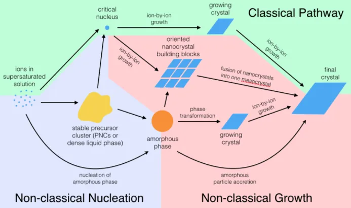
Several different and possibly overlapping biomineral crystallization pathways exist, as shown in Figure 2.5. There are classical and non-classical theories for both nucleation and growth. Illustrated with a green background in Figure 2.5, the classical growth theory follows textbook crystallization, where the solid nucleates from solution and grows through ion-by-ion attachment dependent on supersaturation levels. Non-classical growth theories are shown with a red background in Figure 2.5. One non-classical theory is that of mesocrystals, which form from the fusion of oriented nano-crystalline building blocks, often stabilized by organic molecules.68 A similar theory is that of accretion of amorphous nanoparticles, whereby amorphous particles are nucleated, come together, and then transform to crystalline structures.69 It is also speculated that ion-by-ion attachment to the crystal may occur simultaneously with this particle accretion mechanism, as depicted in Figure 2.6. Figure 2.5 Diagram of the different possible nucleation and growth pathways of biominerals. Classical nucleation and growth theories are depicted with a green background, while non-classical nucleation is shown with a purple background and non-classical growth mechanisms have a red background.Crystalline phases are depicted in blue, while an amorphous phase is orange and an unknown precursor phase is in yellow. See text for more details. The dynamics of ion-by-ion attachment and orientated nanocrystal attachment or amorphous particle accretion should vary greatly within a hydrogel network; thus, different growth pathways should result in different changes of the viscoelastic properties of the hydrogel system and should show different characteristics in rheological measurements. Figure 2.6 Schematic of amorphous particle accretion growth mechanism. Amorphous particles are shown in red, ions in gray, and the growing crystal in dark blue with lines representing the crystal lattice. This theory suggests that crystals grow from the accrual of amorphous particles, alongside ion-by-ion growth. Adapted from ref.69
2.4.1 Classical Nucleation Theory
Although recent findings suggest that some aspects of biologically-controlled biomineralization cannot be explained using classical nucleation theory (CNT) alone, it is still the primary framework within which nucleation of crystals from solution is understood and thus, the general concepts will be examined briefly below. CNT is based on the balance of bulk free energy and surface or interfacial free energy of a cluster of atoms (nucleus) that form a new phase, such as a solid in a supersaturated solution.8 Thiscluster formation is a stochastic process, and when it occurs in the bulk solution, it is referred to as homogeneous nucleation.38 The free energy of formation of a nucleus is a sum of the bulk free energy of the nucleus, ΔGv, a negative, volume-dependent term, and the interfacial free energy, γ, a positive, area-dependent term,70 and for a classical spherical nucleus with radius r can be written as Δ𝐺#$% ='(𝜋𝑟(Δ𝐺++ 4𝜋𝑟.𝛾. The bulk free energy encompasses the driving force for nucleation and is related to the supersaturation—higher supersaturation leads to a more negative bulk free energy. From this equation can be calculated a critical radius, rcrit, below which a nucleus will lower its free energy by shrinking and above which a nucleus would lower its free energy by growing, thus beginning the nucleation and growth process of the new phase. The value of ΔGnuc at rcrit can be thought of as the thermodynamic barrier to nucleation.8 When nucleation occurs at preferred sites, it is referred to as heterogeneous nucleation. These sites could be dust, impurities, or specific molecules added as nucleation promoters, which essentially lower the barrier to nucleation by lowering the interfacial energy of the nucleating species.8 Organic molecules involved in biomineralization often act as heterogeneous nucleation sites and can be responsible for selection of less thermodynamically stable crystal polymorphs in typical environments.7 As seen in Figure 2.3, poly-aspartic acid rich proteins serve as heterogeneous nucleation sites for aragonite tablets in nacre.
2.4.2 Non-Classical Theories—Precursors to Nucleation
According to CNT, any association of ions smaller than the critical nucleus size is unstable and, therefore, will dissolve back into solution. Anything larger is also unstable and grows. However, recent studies33–35 have reported the existence of such (meta)stable solute associations in homogeneous solutions, considered precursors to nucleation, depicted in yellow in Figure 2.5. One theory involves small, stable precursors deemed pre-nucleation clusters (PNCs).38 The exact definition of PNCs is still debated, but in general, they are considered to be small, thermodynamically stable solute clusters on the order of a few nanometers that do not have formal phase boundaries with the surrounding solution but are precursors to phaseseparation.33,38 Many open questions remain regarding their significance in crystal nucleation and growth and their mere existence. One of the challenges of investigating PNCs is that it is difficult to detect them with current techniques. They have only been directly observed in cryo-TEM experiments,34 whose results have recently been questioned by some of the study’s own authors.71 Another developing theory is a two-step mechanism of nucleation, which also involves the idea of precursor clusters.35 Unlike PNCs, however, these clusters are thought to be hundreds of nanometers in size and consist of a dense liquid phase. It is believed that the crystal nucleus forms within this liquid cluster. Developing a rheological technique to observe the mineralization process would help to elucidate the presence of PNCs and dense liquid phases and their roles in biomineralization.
2.5 Hydrogel Mineralization
A hydrogel is a crosslinked polymer network whose entire volume is swollen with water.72,73 The crosslinks can be of covalent nature (chemical gels) or of physical nature (physical gels), such as physical entanglements, hydrogen bonds, hydrophobic interactions, and van der Waals forces. The crosslinking density of a hydrogel modulates its properties, such as stiffness and pore size. The hydrogel pores physically confine portions of the absorbed solution, creating a different mineralization environment than in bulk solution or on a film by allowing control of solute concentration and supersaturation due to limits of diffusion through the gel. Common hydrogels used in biomineralization and crystal growth are gelatin,26,30,74–77 agarose,78–81 silk fibroin,82,83polyacrylamide,84,85 silica,86,87 and alginate.28,88
In addition to modifying the physical environment for mineralization, hydrogels can also regulate the chemical environment through incorporation of soluble species, use of network polymers with charged or polar groups, and/or covalent attachment of functional chemical groups onto the hydrogel matrix.29 Cationic impurities have been used to alter CaCO
27
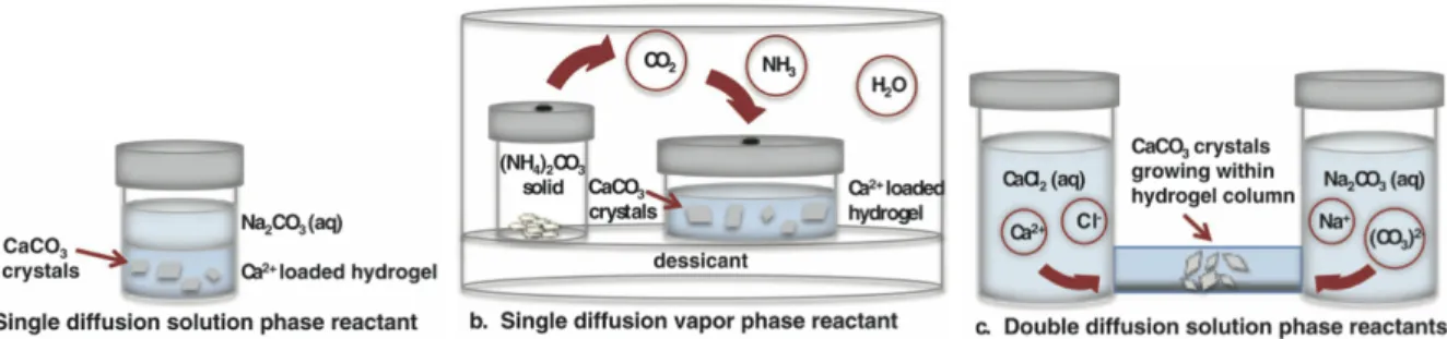
using Mg2+ as a nucleation inhibitor.89 Gelatin, a polymer which has positively and negatively charged groups on its backbone, can directly interact with solute ions, adjusting local ion concentrations or acting as heterogeneous nucleation sites.29 Sulfonated84 and carboxylated85 hydrogel networks have been shown to change CaCO3 growth kinetics and morphology. With these types of modifications, hydrogels can be tailored to grow crystals with specific size, shape, and polymorph. Several different experimental techniques have been developed for growing minerals inside hydrogels. Figure 2.7 depicts three methods, in which the solid forms from the precipitation of two reactants, induced by increasing supersaturation through diffusion of one (single diffusion) or both (double diffusion) reactants.29 In a single diffusion experiment, one reactant is embedded into the hydrogel and the other is allowed to diffuse from a solution covering the gel, as in Figure 2.7a or from a gas phase into the gel, as in Figure 2.7b. For a double diffusion setup, both reactants begin in solution and diffuse from opposite ends of the gel, shown in Figure 2.7c. Figure 2.7Schematic of three common hydrogel mineralization experimental setups. (a) Diffusion of a single solution phase. (b) Diffusion of a single gas phase. (c) Diffusion of both reactants through solution. Adapted from ref.29 For studying early mineralization kinetics within hydrogels, light microscopy is still the common method to detect the first visible crystal nuclei.30 Because of magnification and resolution limits (typically ~0.2 microns), the detection of the first nuclei does not correspond to the time of actual nucleation, where only small clusters of atoms have come together (angstrom-nm scale).
2.5.1 Gelatin Hydrogels
Gelatin is made by the partial hydrolysis of collagen, a major structural protein found in animals.90 When gelatin solutions are heated to above 40°C, the gelatin dissolves to create a viscous solution, in which its molecules behave like random coils.91 When this solution is cooled to below the gelatin helix-coil transition (~35-40°C), triple helical junctions form between gelatin molecules that act as physical crosslinks in the gelatin network, forming a gel.92,93 The three most pronounced amino acids found in gelatin (glycine, proline, and hydroxyproline) are known to be important in the formation of the collagen triple helices.94 Intermolecular hydrogen bonding, facilitated by the glycine-rich sequences, stabilize the triple helical junctions. Thus, the kinetics of gelation and the properties of the gel, are very sensitive to the environmental parameters during gelation, such as gelation temperature and time. Gelatin is amphoteric, having amino acid residues with both positively- and negatively-charged side groups. The specific charge characteristics of gelatin depends on its processing and the solution pH. Gelatin is not believed to interact in a specific chemical manner with CaCO3; however, during mineralization, the charged side groups of gelatin molecules may interact electrostatically with dissolved ions, such as negative carboxylic acid groups with positive Ca2+ ions. This local concentration of Ca2+ ions could lead to the attraction of negative CO32- ions andthus, the formation of CaCO3 nuclei. Therefore, positions on the gelatin backbone may act as heterogeneous nucleation sites for growing minerals.29
2.5.2 Metal-Coordinate Hydrogels
Metal-coordinate hydrogels are a type of supramolecular gel where the crosslinks are formed through coordinate covalent bonds between multiple ligands and a metal ion center.95 Coordinate bond binding energies largely fall in between those of strong covalent bonds and weaker bonds like hydrogen bonds, making them relatively strong but often reversible. In addition to simply changing the backbone polymer, hydrogel mechanical properties can betailored by using different combinations of ligands and metal ions to alter the bond energies and association/dissociation kinetics. For this thesis, we will focus on hydrogels whose metal-coordinate chemistries are inspired by mussel byssal threads. These holdfast threads are secreted under highly-controlled conditions and adhere the mussel to rocks and other hard substrates, keeping them anchored in rough waters.96 One of many key components in the mussel foot proteins found in the byssal adhesive plaque and thread coating is the modified amino acid 3,4- dihydroxyphenyl-L-alanine (DOPA), whose catechol moiety forms strong coordinate complexes with Fe3+ and other transition metal ions.97 In the core of the threads, histidine residues predominate and coordinate with divalent metal ions, such as nickel and copper, forming complexes which are hypothesized to impart the self-healing properties of mussel fibers.98,99 In recent years, our group and others have designed synthetic hydrogels using both catechol-100–103 and histidine-based104–107 metal-coordinate
crosslinks. To obtain a simple, well-controlled network, we primarily use 4-arm polyethylene glycol (PEG) functionalized with either catechol or histidine end groups, which coordinate with metal ions in a bis (two ligands per metal ion) or tris (three ligands per metal ion) fashion to form viscoelastic gels. Typically, we use Fe3+ ions for catechol gels and Ni2+ or Cu2+ ions for histidine gels, but other di-/trivalent transition metal ions can also form gels with different mechanical properties.101,105,107 Our group has also fabricated metal-coordinate hydrogels where iron oxide nanoparticles are the crosslinking centers of a catechol gel rather than Fe3+ ions.108 These
nanoparticle gels exhibit very different mechanical properties than ion gels, a discovery which inspired some of the work in this thesis where we attempt to grow iron oxide particles in situ from an Fe3+ metal-coordinate gel.
2.6 Oscillatory Rheology
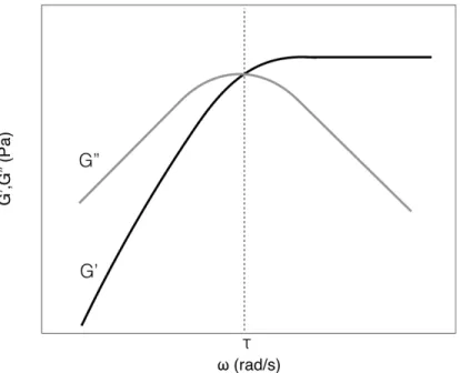
Oscillatory rheology is used to characterize the mechanical properties of viscoelastic systems, such as gels. Small amplitude oscillatory shear (SAOS) rheology measures these properties within the linear viscoelastic regime, at small deformations. A standard SAOS measurement is the stressresponse of the gel to an oscillatory shear strain at different frequencies. The stress is a function of the storage modulus (G’), or stiffness, and loss modulus (G”), which correspond to the material’s elastic and viscous nature, respectively, and are typically graphed versus the frequency, as shown in Figure 2.8.109 Figure 2.8 A typical rheological graph of G’ (solid) and G” (hollow) against frequency, including a crossover point indicating a transition from liquid- to solid-like behavior at higher frequencies. When G’ > G”, the material is dominated by its elastic response and is deemed more solid-like, while it is dominated by its viscous properties and is more fluid-like when G” > G’. Gels often show a crossover point in G’ and G”, as in Figure 2.8, which indicates the frequency at which the material changes from responding more like a solid than a liquid. The inverse of this frequency is often described as the material’s characteristic relaxation time, τ. The rheometer can also be set to measure the stress response at a given frequency over a period of time, which can be useful to observe a sol-gel transition at a crossover point.72 These types of time measurements would also be expected to show changes in G’ and G” over the course of in situ mineralization experiments, which would then provide information of the timescales at which mineralization events occur. Large amplitude oscillatory shear (LAOS) rheology measures materials’ nonlinear viscoelastic properties, whose mechanical response is dependent on the strain amplitude, in addition to the strain rate. There are four basic types of LAOS responses with increased strain
amplitude: strain thinning (decrease in G’ and G”), strain hardening (increase in G’ and G”), weak strain overshoot (local maximum in G”), and string strain overshoot (local maxima in G’ and G”).110 Materials in the real world are often subjected to conditions that push them beyond their linear viscoelastic limits. Thus, LAOS measurements can be integral to understanding material behavior.
2.7 Sustainable Materials Processing & Applications
2.7.1 Green Chemistry & Sustainable Engineering
The concept of green chemistry emerged in the early 1990s as a design approach to eliminate or reduce hazardous substances in chemical products and processing. It has since evolved into an organized design framework with a guiding set of twelve principles that encompasses all aspects of chemical production to achieve sustainability at the molecular level.111 Subsequently, a separate but complementary framework for green engineering was developed with its own twelve principles, focusing on a broader systems approach to realizing sustainability through science and technology.1 Over the last 20 years, green chemistry has flourished into a field unto its own, encompassing hundreds of diverse research avenues among its different principles.2 While the work presented in this thesis was not designed as a whole with every principle in mind—the ideal usage for which the green chemistry and engineering principles were conceived—we draw inspiration from several key principles, namely: avoiding toxic reagents, using water as a preferred solvent alternative, reducing energy use through ambient temperature and pressure conditions, and using renewable feedstocks.1,111 Around the same time that green chemistry was developing, the field of nanotechnology was also emerging and similarly promising technological solutions to energy and environmental challenges. Appropriately, researchers began to apply the green chemistry principles to nanotechnology, creating green nanoscience for the sustainable design and production of nanomaterials.112–114 Among the greener strategies developed for synthesizing nanoparticleswith controlled properties is using templates as growth media.113,115 In this thesis, our work uses hydrogels as these templates to grow metal oxide nanoparticles at ambient conditions in an aqueous environment. Our growth of magnetite is particularly relevant to green chemistry, as these magnetic nanoparticles are becoming a popular substrate to immobilize catalysts for facile magnetic separation enabling catalyst recycling for chemical reactions.116,117
2.7.2 Mineral Carbonation
Mineral carbonation (MC) is a process in which CO2 is stored through the mineralization of calcium- or magnesium-bearing minerals or ions into stable carbonates.118 This mineralization process can be achieved in many different ways, including in situ direct mineralization by injecting CO2 into geological formations, ex situ mining of calcium and magnesium silicates followed by direct reaction with CO2, and indirect carbonation, whereby reactive ions are first extracted from minerals before reaction with CO2.119 In situ MC has the benefit of limited transportation after mineralization of products but also has safety concerns with potential leakage and with causing unpredictable large-scale environmental changes. Ex situ MC has the benefit of secure, permanent storage but still requires large energy inputs for the mining process. This can be avoided by using waste streams to provide the calcium or magnesium mineral components, but other constituents of the waste stream create impurities in the carbonate, which can then only be used in low grade applications. Indirect MC of calcium- and magnesium-rich waste streams is able to produce pure carbonates that have the potential to be used in higher quality applications. However, the additional extraction step adds significant costs to the MC process, which makes it undesirable.118 If pure CaCO 3 crystals of specific polymorph, shape, and size could be made from the MC process, their high value could offset the costs of extraction. A tailored hydrogel system could provide the necessary control over crystal growth to enable the production of CaCO3 minerals as high value products for industries such as plastics, paper, cosmetics, paints, and pharmaceuticals.120
2.7.3 Hydrogel Composites
Hydrogel (nano)composites are combinations of hydrogel networks and a variety of inorganic (nano)particles or carbon-based nanomaterials, wherein the particles are incorporated into the hydrogel as entrapped fillers or have more specific bonding with the polymer chains of the hydrogel, even participating in the hydrogel crosslinking mechanism. Incorporation of these particles can impart improved or new properties to the hydrogel, such as mechanical reinforcement or functional performance, like the addition of electrical, magnetic, or optical properties. Thus, hydrogel composites have been studied for a wide range of applications, particularly in drug delivery and biomedical applications, as well as environmental remediation.121–123 Some of the first nanocomposite hydrogels were poly(N-isopropylacrylamide) (PNIPAM) gels crosslinked with nanoclay sheets studied by Haraguchi et al.124 These showed higher toughness and extensibility compared to covalently crosslinked PNIPAM gels and have since sparked considerable research into mechanically superior clay hydrogels125,126 and other hydrogel composites,127–130 including work in our group on iron oxide nanoparticle hydrogels.108 Incorporating iron oxide into hydrogels has become particularly interesting for the development of magnetic, responsive hydrogels for applications such as magnetic targeting and magnetocaloric heating/cooling for drug delivery and wastewater treatment.131 Current limitations of magnetic hydrogels include a common tradeoff between magnetic and mechanical properties and the random orientation of the incorporated nanoparticles. In situ mineralization of the nanoparticles within the hydrogel network could enable greater control over the spatial and chemical incorporation of the particles, helping to solve these issues.
Chapter 3
Rheology as a Mechanoscopic Method to
Monitor Mineralization in Hydrogels
Reproduced in part with permission from Regitsky, A. U., Keshavarz, B., McKinley, G. H. & Holten-Andersen, N. Rheology as a Mechanoscopic Method to Monitor Mineralization in Hydrogels. Biomacromolecules 18, 4067–4074 (2017).132 Copyright 2017 American Chemical Society. The full text of this article can be viewed at http://pubs.acs.org/articlesonrequest/AOR-UWdbfSqH6d6Feg2x5u8u3.1 Introduction
As described in previous chapters, biominerals have been widely studied due to their unique mechanical properties, afforded by their inorganic–organic composite structure and well-controlled growth in macromolecular environments. However, a lack of suitable characterization techniques for inorganic minerals in organic-rich media has prevented a full understanding of biomineralization. In this chapter, we applied rheometry to study mineral nucleation and growth dynamics by measuring viscoelastic material properties of a hydrogel system during mineralization. Our proof-of-concept system consists of a gelatin hydrogel matrix preloaded with calcium ions and a reservoir of carbonate ions, which diffuse through the gel to initiatemineralization. We found that gels with diffused carbonate show an increase in low frequency energy dissipation, which scales with carbonate concentration and gel pH. Using this signal, and recognizing that mineralization occurs simultaneously with carbonate diffusion in our system, we have mechanoscopically tracked mineral growth in situ, showcasing the potential of rheometry for studying mineralization kinetics in real time. Despite intense studies on their structure and formation, questions on early thermodynamics and kinetics of biomineral nucleation and growth still remain. Accordingly, recent advances in high resolution electron microscopy such as cryo-TEM34,133,134 and liquid cell TEM135,136 have been employed to capture early mineralization events, providing subnanometer resolution images of mineral growth frozen in time137 and real-time videos of in situ mineral phase transformations,135 respectively. These and other recent studies have afforded insights into nonclassical nucleation and growth pathways of biominerals, such as amorphous
precursors,36,135,138 prenucleation clusters,33,34,37 dense liquid phases,35,139 and oriented aggregation by particle attachment,69,134,137 wherein organic molecules are hypothesized to function as nucleation enhancers or inhibitors or as cluster stabilizers.140,141 However, high-resolution electron microscopy techniques are static measurements of structure, not of material properties, and they do not allow in situ studies of biomineralization within hydrogel-like organic matrices. It remains difficult to detect nuclei within gels,29 and experiments are limited to studying nucleation by extrapolation from visual observation of crystal growth instead of actual nuclei formation.30 Furthermore, because of the crowded macromolecular environment and solution confinement in pores, mineralization in gels varies greatly from that in solution, and mineralization studies in dilute aqueous solutions therefore cannot substitute for mineralization in macromolecular hydrogel media. Hence, prenucleation and early mineral growth remain uncharacterized in hydrogel systems using current experimental techniques. In this chapter, we propose rheometry as a mechanical characterization tool for observing the growth of minerals in hydrogels. In particular, we use small amplitude oscillatory shear (SAOS) rheology to monitor the changes in linear viscoelastic mechanical properties of a gelatin
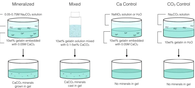
hydrogel system with CaCO3 mineral deposits. While rheology has been used previously to characterize general viscoelastic properties of mineralized hydrogels,142,143 we specifically seek to deconstruct the unique mechanical contributions from the minerals, the hydrogel matrix, and the mineral–hydrogel interface to observe and quantify mineral growth in situ. We investigated the mechanical differences between gels which have CaCO3 particles grown directly within the gel, CaCO3 particles physically mixed into the gel, and gels with no minerals, shown in Figure 3.1 as mineralized, mixed, and control gels, respectively. In all gel systems, we observed increased viscous dissipation in direct correlation with Na2CO3 solution concentration. Since mineralization is controlled directly through carbonate diffusion in the supersaturated gel conditions used here, we used this specific carbonate mechanical signal to track the growth of minerals in situ and in real time. We also used scanning electron microscopy, thermogravimetric analysis, and x-ray powder diffraction to characterize the mineral particles grown in the hydrogel composite systems. Figure 3.1 Diagram of sample preparation procedures for “mineralized” and “mixed” gels, where CaCO3 particles are either grown in the gel or manually mixed in, respectively, and for control gels without minerals. Gels are then characterized mechanically using small amplitude oscillatory rheology. 0.05-0.75M Na2CO3 solution 10wt% gelatin embedded with 0.05M CaCl2 CaCO3 minerals grown in gel
10wt% gelatin solution mixed with 0.1-5wt% CaCO3 CaCO3 minerals cast in gel Mineralized Mixed No minerals in gel NaNO3 solution or H2O 10wt% gelatin embedded with 0.05M CaCl2 Ca Control CO3 Control No minerals in gel 10wt% gelatin in H2O Na2CO3 solution
3.2 Results & Discussion
3.2.1 Mineralized CaCO
3Characterization
To create mineralized gels with different mineral contents, we varied the concentration of Na2CO3mineralizing solution from 0.05 to 0.75 M. We calculated the volume fraction of grown
particles from mass fractions measured using TGA, assuming CaCO3 density of 2.711 g/cm3 and
gelatin solution density similar to that of water (1 g/cm3).44 As shown in Figure 3.2a, we achieved
a range of CaCO3 volume fractions from 0 to 1.8%, with higher Na2CO3 concentration resulting in
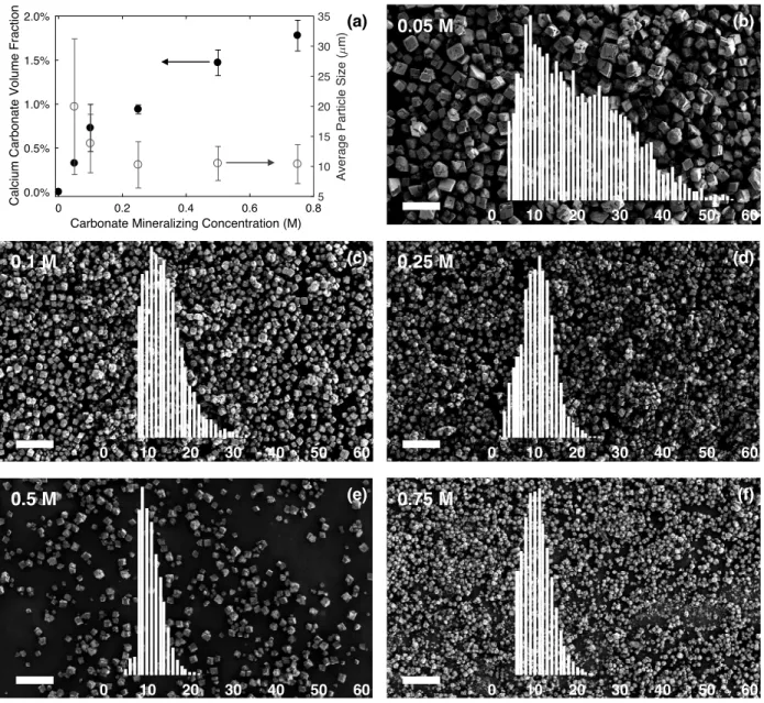
higher mineral volume fractions. We also characterized the particle sizes using SEM to understand how the average particle sizes and size distributions changed with varying Na2CO3 concentration. Particle sizes generally decreased with increasing Na2CO3 concentration to an average of ∼10 μm, as depicted in Figure 3.2a. Figure 3.2b–f illustrates representative SEM images of particles grown using each Na2CO3 concentration with insets of the particle size distributions. At higher concentrations of Na2CO3, a higher rate of nucleation is in effect, leading to a larger number of particles of smaller size, while at lower concentrations of Na2CO3, a lower nucleation rate enables particles nucleated earlier to grow larger, leading to a broader distribution. The particle size distribution obtained from the 0.05 M Na2CO3 solution may indicate a bimodal distribution, which would account for the large standard deviation in sizes.
Figure 3.2 Properties of mineralized CaCO3 particles grown in gels after 1 h. (a) CaCO3 volume fraction
(closed circles) and average particle size (open circles) as a function of the concentration of Na2CO3 solution used for mineralization. (b–f) Representative SEM images of particles grown with increasing Na2CO3solution concentration (top left of each image). Overlays show particle size distributions in μm. The density of the particles in the images are a result of the sample preparation procedure for SEM and are not a reflection of the particle density within the gel. All scale bars are 100 μm. In addition to enabling particle size measurements, SEM images depicted rhombohedral particle morphologies for all samples, indicative of the calcite polymorph. X-ray powder diffraction (XRPD) of mineralized particles confirmed calcite as the dominant polymorph, as evidenced in Figure 3.3. The difference in relative peak intensities of the sample and the reference can be 0 0.2 0.4 0.6 0.8
Carbonate Mineralizing Concentration (M)
0.0% 0.5% 1.0% 1.5% 2.0%
Calcium Carbonate Volume Fraction 5
10 15 20 25 30 35
Average Particle Size (
m) 0 10 20 30 40 50 60 0 10 20 30 40 50 60 0 10 20 30 40 50 60 0 10 20 30 40 50 60 0 10 20 30 40 50 60 0.05 M 0.1 M 0.5 M 0.75 M 0.25 M (b) (c) (d) (e) (f) (a)
attributed to preferred orientation of the sample during mounting. The most intense peak at ~29° coincides with the [104] direction, which corresponds to the lowest energy cleavage plane of calcite and is often found to be the direction of the faces of mineralized calcite
rhombohedra.87
Figure 3.3 (a) XRPD spectrum of CaCO3 particles grown in 10wt% gelatin in 0.05M CaCl2, with a 0.5M
Na2CO3 mineralizing solution. (b) Calcite reference peaks. When comparing the sample peaks to the calcite reference, it is clear that the sample displays the calcite polymorph.
3.2.2 Rheological Characterization
We conducted frequency sweeps to measure the storage moduli (Gʹ) and loss moduli (Gʺ) of all gel samples. All gels showed solid-like behavior, with Gʹ > Gʺ across all frequencies measured, as shown in Figure 3.4a. These data are taken from one sample from each of the four types of gels and are representative of the mechanical behavior of the whole group (see Figure 3.5 for the complete set of data). In correlation with the presence of carbonate, we observed two marked differences in mechanical behavior of mineralized and CO3 control gels compared to mixed and Ca control gels: higher values of Gʹ across the frequency spectrum and an increase in Gʺ at low frequencies. We anticipated higher values of Gʹ from mineralized samples, likely from the interaction of gelatin with the surface of CaCO3 particles and potential incorporation of gelatin molecules within the growing particles,29 but we did not expect significant changes in the gelatin system from the presence of carbonate ions alone. Regardless, because of the high reactant (a) (b) 0concentrations—and thus, high levels of supersaturation—used in our experiments, mineralization correlates closely with the diffusion of carbonate ions into the calcium-loaded gel. Therefore, the mechanical differences associated with the presence of carbonate can be used as indirect signals of the growth of minerals. In particular, the increase in Gʺ at low frequency offers a unique signature of the growing presence of particles in mineralized systems. We further explore this increase in dissipation in Figures 3.6 and 3.7 below. Figure 3.4 (a) Representative graph of the storage and loss moduli of mineralized (circle), mixed (square),
and control samples (Na2CO3 control–star, CaCl2 control–asterisk) from 0.1 to 100 rad/s angular
frequency. (b) Same data from (a) replotted as tan(δ) to simplify the data representation and highlight the
enhanced low frequency dissipation signature of the mineralized and CO3 control samples.
10-1 100 101 102
Angular Frequency (rad/s) 102
103 104
Storage and Loss Moduli (Pa)
10-1 100 101 102
Angular Frequency (rad/s)
0 0.01 0.02 0.03 0.04 0.05 0.06 0.07 Tan( ) (a) (b)
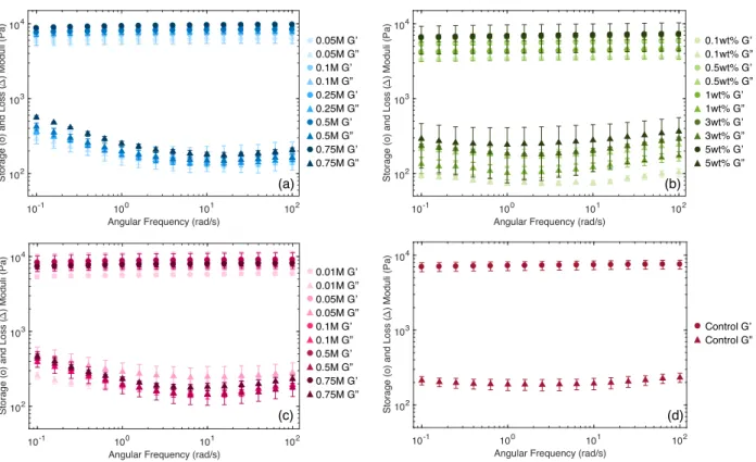
Figure 3.5 Averaged frequency sweep data for all samples tested. (a) Mineralized samples with increasing Na2CO3 mineralizing solution depicted in darker shades. (b) Mixed samples with increasing weight percent of mixed in CaCO3 particles shown in darker shades. (c) Carbonate control samples with increasing Na2CO3 mineralizing solution depicted in darker shades. (d) Calcium control average with H2O used as the Na2CO3 substitute solution. To simplify the presentation of rheological data based on this low frequency dissipation signature, we use the loss tangent (tan(δ) = Gʺ/Gʹ). Figure 3.4b depicts the same data as in Figure 3.4a converted to tan(δ). Here, the increase in tan(δ), or energy dissipation, at low frequencies is even more clear. Because this signature is evident only at low frequencies, we are able to further simplify the differences between samples by using a single value of tan(δ) at ω = 0.1 rad/s, normalized by the minimum value of tan(δ), which we call Δtan(δ) = (tan(δ)ω=0.1rad/s –
tan(δ)min). To maintain a low mutation number, which is defined as the ratio between the
measurement time of a single data point and the gelation time scale characterizing the evolution in viscoelastic properties of the gel, we opted not to go to lower frequencies.144 For in situ
measurements, it is important to maintain a mutation number smaller than unity, which for our system, limits the lower bound of frequency to 0.1 rad/s.
10-1 100 101 102
Angular Frequency (rad/s) 102
103 104
Storage (o) and Loss (
) Moduli (Pa)
10-1 100 101 102
Angular Frequency (rad/s) 102
103 104
Storage (o) and Loss (
) Moduli (Pa)
10-1 100 101 102
Angular Frequency (rad/s) 102
103 104
Storage (o) and Loss (
) Moduli (Pa)
10-1 100 101 102
Angular Frequency (rad/s) 102
103 104
Storage (o) and Loss (
) Moduli (Pa) (c) (b) (d) 0.05M G’ 0.05M G” 0.1M G’ 0.1M G” 0.25M G’ 0.25M G” 0.5M G’ 0.5M G” 0.75M G’ 0.75M G” (a) 0.01M G’ 0.01M G” 0.05M G’ 0.05M G” 0.1M G’ 0.1M G” 0.5M G’ 0.5M G” 0.75M G’ 0.75M G” 0.1wt% G’ 0.1wt% G” 0.5wt% G’ 0.5wt% G” 1wt% G’ 1wt% G” 3wt% G’ 3wt% G” 5wt% G’ 5wt% G” Control G’ Control G”
To better understand how the low frequency dissipation signature correlates with gel mineralization, in Figure 3.6 we plot Δtan(δ) for gels with respect to (a) particle volume fraction and (b) Na2CO3 mineralizing solution concentration. Figure 3.6a shows that Δtan(δ) increases with particle volume fraction in mineralized samples, while there is no increase in Δtan(δ) with the particle volume fraction that is mixed in. However, Figure 3.6b shows that similar values of Δtan(δ) are achieved in CO3 control samples with no particles. These data confirm that the presence of mineral alone does not lead to increased dissipation and that the magnitude of Δtan(δ) correlates with the amount of carbonate in the gel. To further test this correlation, we diffused 0.5 M Na2CO3into mixed gels and observed a corresponding increase in Δtan(δ) independent of CaCO3 particle content (see Figure 3.6a and 3.6b).
Figure 3.6 Variation in Δtan(δ) (tan(δ)ω=0.1 – tan(δ)min) of all gels with respect to (a) CaCO3 volume fraction
in the gel and (b) Na2CO3 mineralizing solution concentration. Samples represented include mineralized
(circle), mixed (square), Na2CO3 control (star), CaCl2 control (asterisk), and mixed + Na2CO3 (triangle).
Notice the collapse of data points from (a) to (b) of mixed + Na2CO3 samples with varying CaCO3 volume
fraction but identical Na2CO3 solution concentration.
It has been widely observed that the mechanical properties of gelatin can depend strongly on various aspects of the system, including pH,145–147 salt concentration,148 and other dissolved
species, such as surfactants.149 Specifically, studies have shown increases in storage moduli of gelatin gels at higher pH,150 which may explain the higher moduli observed for gels exposed to Na2CO3 (see Figure 3.4a) given that Na2CO3 is a base. However, the link between pH and viscoelastic dissipation in hydrogels has not been thoroughly explored. When plotting Δtan(δ) against the pH of CO3 control gels, we observe a tight linear correlation (see Figure 3.7), but gels 0 0.4 0.8 1.2 1.6 2
Calcium Carbonate Volume Fraction (%)
0 0.01 0.02 0.03 0.04 0.05 0.06 Tan( ) (a) 0 0.2 0.4 0.6 0.8
Na2CO3 Mineralizing Solution Concentration (M)
0 0.01 0.02 0.03 0.04 0.05 0.06 Tan( ) (b)
exposed to basic pH using NaOH, without the presence of carbonate, do not show the same mechanically dissipative behavior. These results strongly suggest that carbonate-specific interaction with the gel network, rather than gel pH, is the major source of the observed dissipation. One possible explanation of this carbonate-induced dissipation is the association of divalent CO32– ions with the gelatin matrix. Simulations by Tlatlik et al. revealed that hydrogen
bonding between PO43– and HPO42– ions and the collagen triple helix caused some bending of the
collagen molecules, increasing flexibility.151 A similar association mechanism could be occurring between CO32– ions and collagen triple helices in our system, leading to increased dissipation at longer time scales (corresponding to lower frequencies) due to gelatin network helical bending. This additional hydrogen-bonding capacity from the presence of CO32– ions could also be leading to increased associations between gelatin molecules, resulting in a long-time relaxation mode similar to the α*-relaxation described by Shabbir et al. when hydrogen-bonding moieties were added to their polymer melt system.152 They used rheology as well as dielectric relaxation spectroscopy to characterize this low frequency relaxation mode, revealing dielectric spectroscopy as another potential useful characterization technique for mineralization studies. Figure 3.7 Δtan(δ) with respect to gel pH for Na2CO3 control samples (star) and gels exposed to NaOH (plus sign) to produce a high pH environment without the presence of carbonate. 8 9 10 11 12 pH 0 0.01 0.02 0.03 0.04 0.05 0.06 Tan( )
In addition to increased dissipation due to the presence of CO32– ions, there may also be a smaller contribution to low frequency dissipation from the interaction of the grown minerals with the gelatin network. Studies have shown the appearance of a longer time, α*-like, relaxation mode associated with the addition of filler particles to rubber networks due to organic–inorganic interfacial interactions.153 Elucidating the exact contributions of the minerals and CO32– ions to the increased low frequency dissipation in the system would require further study.
3.2.3 In Situ Mineralization
Next, we wanted to utilize the low frequency mechanical dissipation signal to monitor changes in mineralization in situ and in real time. The experimental setup is depicted in Figure 3.8a. We gelled the gelatin on the rheometer and added the Na2CO3 mineralizing solution after beginning G’ and G” measurements. Figure 8b demonstrates a clear increase in tan(δ)|ω=0.1 over time during in situ mineralization in a gel, whereas tan(δ)|ω=0.1 remains constant for the Ca control. To ensure that the rheological probing of the system during mineral growth was not affecting the results, we also conducted a control experiment with rheological measurements delayed until after mineralization had occurred. The close correspondence of the data (see Figure 3.9) confirmed the noninvasiveness of the technique. While further analysis is required to fully understand what aspects of mineral growth are encapsulated in the time evolution of tan(δ), our results confirm the ability of rheology to nondestructively probe mineral growth in gels in real time.Figure 3.8 (a) Schematic of the in situ mineralization setup using a parallel plate geometry with the calcium-loaded gelatin gel surrounded by the carbonate solution. The carbonate diffuses radially inward. Dimensions are not drawn to scale. (b) Evolution of tan(δ) at ω = 0.1 rad/s over time for a gelatin gel undergoing in situ mineralization (open circle) and a CaCl2 control sample (asterisk). Figure 3.9 Data from control experiment to test non-invasiveness of in situ mineralization technique. Original data in blue; non-invasive control data in red. (a) Tanδ at ω = 0.1 rad/s and (b) the oscillatory strain amplitude (or invasiveness) of the measurement over time. (c) Post-mineralization tanδ over multiple angular frequencies. The parallel plate geometry used above is not ideal for this type of experiment since it creates a radially inhomogeneous gradient of particle growth within the gel. Hence, further rheological
Ca
2+Ca
2+CO
32-CO
3 2-102 103 104 Time (s) 0 0.01 0.02 0.03 0.04 0.05 0.06 Tan( ) at = 0.1 rad/s 60 mm 25 mm 1 mm (a) (b) 10-1 100 101Angular Frequency (rad/s)
0.01 0.02 0.03 0.04 0.05 0.06 Tan( ) After Mineralization Mineralized Non-invasive Control 102 103 104 Time (s) 0 1 2 3 4 5
Oscillatory Strain Amplitude (%)
Mineralized Non-invasive Control 102 103 104 Time (s) 0 0.01 0.02 0.03 0.04 0.05 0.06 Tan( ) at = 0.1 rad/s Mineralized Non-invasive Control (a) (b) (c)
data analysis is complicated because we cannot determine how much of the system has been mineralized (radially) at any given time. Therefore, we also conducted in situ mineralization experiments using a cylindrical Couette geometry with a transparent outer cylindrical wall, schematically depicted in Figure 3.10a. This geometry has a larger surface area over which the CO32– ions can diffuse, and the transparent outer cylinder allowed us to monitor visually the axial fraction of the gel that has mineralized. The Couette geometry also enabled us to capture live images showing crystal growth over time, as shown in Figure 3.10b. Figure 3.10c depicts ΔL, the axial distance of the mineralization front from the gel/solution interface, over time, which represents the growth of the mineralized portion of the gel. Dashed lines connect the images in Figure 3.10b to corresponding time points in Figure 3.10c. Finally, Figure 3.10d portrays the time evolution of tan(δ) of the gelatin–CaCO3 system at nine different frequencies. Here, tan(δ) is normalized by the initial value of tan(δ) to more clearly show the relative changes in tan(δ) over time at various frequencies. The largest change in tan(δ) occurs at a frequency of 0.1 rad/s, the lowest frequency measured, confirming that probing the mineral–gel system at lower frequencies gives more sensitivity overall, and especially at earlier times during mineralization. Furthermore, the essential similarity of the shapes of the mineralized tan(δ)|ω=0.1 curves in Figures 3.8b and 3.10d, captured using different instruments and different measurement geometries, reveals that rheological measurements are indeed robust characterization tools for quantifying the dynamics of mineral growth in hydrogels.
Figure 3.10 (a) Schematic of the in situ mineralization setup using a cylindrical Couette geometry with the calcium-loaded gelatin gel shown in dark gray and the carbonate solution shown in light gray. The carbonate diffuses axially downward. Dimensions are not drawn to scale. (b) Images of the gelatin gel during in situ mineralization at various time points in the cylindrical Couette geometry. The sharp, horizontal line toward the top of each image is the interface between the top of the gel and the carbonate solution. (c) Distance of the mineralization front from the interface over time, showing growth of the mineralized fraction of the gel. Dashed lines connect data points at various times to corresponding images in (b). (d) Evolution of tan(δ) at varying frequencies over time, indicating the greatest increase in dissipation at the lowest frequency of ω = 0.1 rad/s.