Publisher’s version / Version de l'éditeur:
ECS Transactions, 28 (2010), 32, pp. 45-56, 2010-04-30
READ THESE TERMS AND CONDITIONS CAREFULLY BEFORE USING THIS WEBSITE.
https://nrc-publications.canada.ca/eng/copyright
Vous avez des questions? Nous pouvons vous aider. Pour communiquer directement avec un auteur, consultez la première page de la revue dans laquelle son article a été publié afin de trouver ses coordonnées. Si vous n’arrivez pas à les repérer, communiquez avec nous à [email protected].
Questions? Contact the NRC Publications Archive team at
[email protected]. If you wish to email the authors directly, please see the first page of the publication for their contact information.
Archives des publications du CNRC
This publication could be one of several versions: author’s original, accepted manuscript or the publisher’s version. / La version de cette publication peut être l’une des suivantes : la version prépublication de l’auteur, la version acceptée du manuscrit ou la version de l’éditeur.
For the publisher’s version, please access the DOI link below./ Pour consulter la version de l’éditeur, utilisez le lien DOI ci-dessous.
https://doi.org/10.1149/1.3507926
Access and use of this website and the material on it are subject to the Terms and Conditions set forth at
Electrocatalytic Activities of Perovskite toward Oxygen Reduction Reaction in Concentrated Alkaline Electrolytes
Li, XiaoXia; Qu, Wei; Zhang, JiuJun; Wang, HaiJiang
https://publications-cnrc.canada.ca/fra/droits
L’accès à ce site Web et l’utilisation de son contenu sont assujettis aux conditions présentées dans le site LISEZ CES CONDITIONS ATTENTIVEMENT AVANT D’UTILISER CE SITE WEB.
NRC Publications Record / Notice d'Archives des publications de CNRC:
https://nrc-publications.canada.ca/eng/view/object/?id=b7eae5d5-dfdb-4002-bb37-d2ce7d0a9c7c https://publications-cnrc.canada.ca/fra/voir/objet/?id=b7eae5d5-dfdb-4002-bb37-d2ce7d0a9c7c
Electrocatalytic Activities of Perovskite toward Oxygen Reduction Reaction in Concentrated Alkaline Electrolytes
XiaoXia Li, Wei Qu∗, JiuJun Zhang, HaiJiang Wang National Research Council, Institute for Fuel Cell Innovation
Vancouver, BC, Canada, V6P 1W5
Perovskite La0.6Ca0.4CoO3 powder was prepared through a sol-gel method and characterized by XRD and BET. The electrocatalytic properties of La0.6Ca0.4CoO3 (LCCO) and La0.6Ca0.4CoO3-Carbon composite (LCCO-C) based electrode layers towards oxygen reduction reaction (ORR) were studied using rotating ring-disk electrode technique (RRDE) in 1, 4, and 6 M KOH electrolytes. Koutechy-Levich theory and RRDE measurement were applied to acquire the overall electron transfer number and kinetic parameters, such as the kinetic currents and rate constants. The overall electron transfer number was measured to be almost 4 for both pure LCCO and composite LCCO-C. A synergetic effect toward the ORR was observed in the LCCO electrode layer in the presence of carbon. This synergetic effect might be one of the reasons for the improved ORR performance on the composite LCCO-C electrode.
Introduction
Metal-Air rechargeable batteries, in particular Zinc-Air Rechargeable Batteries (ZARBs), have drawn great attention in recent years due to their advantages of high specific energy, low cost, and safe operation in several possible application areas such as portable, backup-power, and automobile. However, the major challenge of the relatively low performance and insufficient stability of the bi-functional air-electrode in current ZARB technology hinders further progress. (1-3).
In literature (1, 4-6), Lanthanum-based perovskite-type oxides (LnBO3, Ln= La, or partially substituted by Ca or Sr; B= Co, Mn, or Fe) have been extensively studied as the air-electrodes due to their high catalytic activities towards the ORR, high oxide ion mobility, mixed ionic and electronic conductivity, as well as environmental benign features. These kinds of materials also possess catalytic activities towards oxygen evolution reaction (OER), making them a candidate for bi-functional electrode in metal-air rechargeable batteries. Another advantage of perovskite is that their structures can be tailored by partially substituting Ln or B site cations within a perovskite structural frame to reach a compromise between their catalytic activities, oxygen adsorption properties, and chemical stability in concentrated alkaline solutions (7-8). Unfortunately, their relatively low conductivity and low specific surface area remain limitation for air-electrode applications (9). In order to increase both the conductivity and surface area, these perovskite-type oxides were mixed with high surface area carbon black to form a composite electrode. The carbon particles serve as the reaction sites for both the ORR
∗
and the OER during the discharging and charging processes of the ZARB air-electrode. For example, compositeLa1-xCaxCoO3 materials were reported to be one of the promising bi-functional electrodes in Zinc-Air rechargeable batteries (10-12). However, the ORR kinetics catalyzed by pure La1-xCaxCoO3 or La1-xCaxCoO3-carbon composite has not been deeply explored, particularly in concentrated alkaline solutions.
As a continuation of research for new cathode materials for zinc-air batteries (13), we investigated the role of carbon towards ORR in composite catalyst by comparing the ORR catalytic performance between pure LCCO and its composite LCCO-C. LCCO was synthesized using a sol-gel method, and characterized using X-ray diffraction (XRD) and the Brunauer Emmett Teller (BET) gas adsorption technique. The LCCO powder was mixed with carbon particles to form composite LCCO-C. The ORR catalytic performance on these two electrodes was studied comparatively using cyclic voltammetry (CV) and rotating ring-disk electrode (RRDE) techniques. The kinetic parameters, including overall electron transfer number, kinetic currents, and kinetic rate constants, on both electrodes were obtained in 1, 4, and 6 M KOH solutions separately.
Experimental
LCCO synthesis and structure characterization
La0.6Ca0.4CoO3 powder was synthesized by sol-gel method in which citric acid, lanthanum nitrate, calcium nitrate, and cobalt nitrate were used to prepare the precursor. Then the formed precursor was treated in air at 650oC for 3 hours. The crystal phase of samples was assessed by XRD. The XRD data were collected with a Bruker D8 Advance diffractometer (Bruker, Cu K-α1 source, =1.5406 Å) over the range 10-90º 2θ-2θ with a scanning rate of 0.1º s–1. The specific surface area measurements were carried out by the gas adsorption technique (BET) method on a surface area analyzer (SA3100, Beckman Coulter).
Working electrode preparation
The carbon used to form LCCO-C composite was a Vulcan carbon powder with a BET surface area of 222 m2 g-1. On a rotating-ring disk electrode (RRDE) tip (AFE7R9GCPT, Pine Research Inc.), a glassy carbon (GC) disk electrode was used as the substrate electrode to prepare both LCCO and LCCO-C electrode layers. The coating ink was prepared by ultrasonically mixing LCCO or LCCO-C powder with appropriate 2-propanol aqueous solution. In the fabrication of electrode layer, a 10 L of coating ink was carefully pipetted on the top of GC disk. Then a 4.0 L of 0.5 wt% Nafion® solution (diluted from 5 wt% Nafion solution, DuPont Co.) was pipetted on the top of this electrode layer. Then the layer was left to dry in air under a 20 W lamp.
Electrochemical measurements
Electrochemical measurements for LCCO and LCCO-C coated electrode were conducted using a Solartron Analytical 1470E Cell Test System. A conventional electrochemical cell containing three electrodes was used for all cyclic voltammetry and RRDE measurements. For the RRDE working electrode, the GC disk and Pt ring had geometric areas of 0.16 cm2 and 0.036 cm2, respectively. The ring electrode collection efficiency of this RRDE was measured to be 0.20±0.01(13). The counter electrode was a Pt mesh and the reference electrode a commercially available Hg/HgO electrode (CH Instruments, Inc.). Deionized water (Millipore SuperQ system, resistivity 18 MΩ cm) was used to prepare the electrolyte solutions with various concentration of KOH. Before
taking cyclic voltammetry measurements, the solution was bubbled with pure N2 (99.99 %) for 30 minutes to remove any dissolved O2. And for the ORR measurements, the solution was saturated by bubbling pure O2 (99.99 %) for 30 minutes.
All experiments were conducted at ambient temperature (23±1oC) and pressure (1.0 atm).
Results and Discussions
Structure and morphology characterization
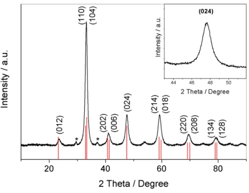
In order to study the phase of the synthesized material, high-resolution XRD patterns were collected for the as-prepared LCCO powder, as shown in Figure 1. It can be seen that the XRD patterns are almost identical to the standard values (JCPDS-ICDD File No. 01-036-1389), which can be readily indexed to the Rhombohedral phase of La0.6Ca0.4CoO3 (space group: R-3m, 166). There are no peaks detected for oxide phases of La2O3 or CoOx, indicating that both of them entered into the perovskite structure. It is noticed that there are two small peaks, marked with asterisks in the spectrum, are still not clear at this moment. According to the peak broaden of (024) (as shown in the inset), the average size of particle was calculated to be ~ 8 nm using the Debye-Scherrer formula (14). The BET measurements were also conducted on this material, and gave a surface area of ~30 m2 g-1.
Figure 1. Typical XRD pattern for La0.6Ca0.4CoO3. The red vertical bars are the standard pattern of the Rhombohedral phase of La0.6Ca0.4CoO3. The inset is the diffraction peak of (024).
Electrocatalytic activities towards ORR and OER
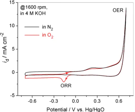
In order to test the electrochemical properties of the synthesized material, LCCO or LCCO-C coated electrode was put into an N2- and O2-saturated 4 M KOH solution for
cyclic voltammetric (CV) measurements in potential range of –0.70 to +0.70 V vs. Hg/HgO. Figure 2 shows the typical results for LCCO-C coated electrode. A sharp upward peak observed at high potential range can be assigned to the oxygen evolution reaction (OER) (15):
4 OH−→ O2 + 2H2O + 4e- [I]
In the negative sweep to the low potentials, a downward peak was observed at –0.16 V, which can be ascribed to oxygen reduction reaction. These observed activities towards both ORR and OER suggest that LCCO-C material synthesized in this work could be a candidate for air-cathode in zinc-air rechargeable batteries.
Figure 2. Cyclic voltammegrams of LCCO-C electrode in potential range of –0.70 ~ +0.70 V vs. Hg/HgO in N2 (black) and O2 (red) saturated 4 M KOH solution. Rotating rate: 1600 rpm, and potential scan rate: 25 mV s-1. LCCO loading: 0.17 mg cm-2.
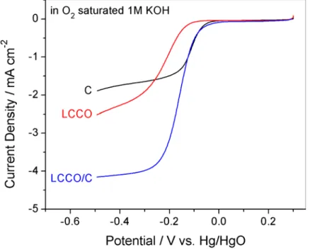
To compare the ORR activities of carbon, LCCO, and LCCO-C, the electrode coated by these three materials were tested using RRDE technique in O2-saturated 1 M KOH, and the results obtained are shown in Figure 3. It can be seen that the onset potential of carbon is more positive than that of LCCO. However, the ORR catalyzed by carbon has a pathway of 2-electron transfer process to produce HO in alkaline solution2− reported in the literature (4). For LCCO, the ORR process has a lower onset potential than that of carbon, indicating the ORR activity of LCCO is less than that of carbon. However, we found, and will discuss in a later section, the ORR catalyzed by LCCO is mainly through a 4-electron pathway to produce −
OH , which is desirable for air-cathode. Fortunately, composite LCCO-C combines the advantages of positive onset potential of carbon and 4-electron pathway of LCCO to give an ORR with positive onset potential and 4-electron pathway to produce −
effect when LCCO and carbon form a composite electrode material. This synergetic effect can be understood according to 2+2-electron transfer pathway. When both LCCO and carbon exist in the electrode layer, O2 would be firstly reduced at the carbon sites to produce HO through a 2-electron pathway, and then the formed 2− HO would find the 2− adjacent LCCO sites to be further reduced to OH . This 2+2-electron transfer pathway − was also proposed by Hermann et al. using a channel flow cell (16).
Figure 3. ORR activity comparison between carbon (black curve), LCCO (red curve) and LCCO-C (blue curve). Electrode rotating rate: 2500 rpm, potential scan rate: 5 mV s-1; The electrode loadings: carbon 0.24 mg cm-2, LCCO 0.17 mg cm-2, and LCCO-C 0.41 mg cm-2; Electrolyte: O2-saturated 1M KOH.
ORR kinetics of LCCO-C electrode measured by RRDE technique
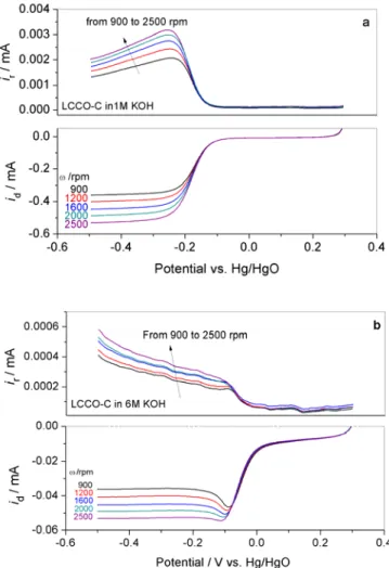
For more quantitative evaluation of the ORR activity of LCCO-based electrode, RRDE technique was employed to obtain the kinetic information in O2 saturated 1, 4, and 6 M KOH solutions. For comparison, both LCCO and LCCO-C coated electrodes were evaluated using the same procedure. Figure 4 shows typical disk and ring currents collected on rotated LCCO-C electrode at different rates from 900 to 2500 rpm in O2 -saturated 1 M and 6 M KOH solutions.
Compared to the case of 1 M KOH solution, the diffusion current (or plateau current) at 6 M KOH solution is about 10 times smaller. The ratio of diffusion currents in 1 M and 6 M KOH is in good agreement to the theoretic ratio calculated in Koutecky-Levich (K-L) plots discussed in our previous work (13). This is due to the decreased solubility and diffusion coefficient of oxygen as well as the increased kinematic viscosity of the electrolyte when the concentration of KOH is increased.
In the case of 6 M KOH solution (Figure 4b),there is a downward peak-like disk current when the potential was scanned from +0.30 V to –0.50 V. It has been recognized
in literature that this peak current comes from the electroreduction of adsorbed O2 inside the thick electrode layer (17). In both the 1 M and 6 M KOH solutions, O2 can adsorb in the electrode layer and give electroreduction currents when the potential is scanned to the ORR kinetic range. However, due to the significantly smaller oxygen concentration in 6 M KOH compared to that in 1 M KOH (0.16×10⁻³ mol L-1 to 0.83×10⁻³ mol L-1) (18), the diffusion current in 6 M KOH is much smaller than the electroreduction current of adsorbed O2 inside the electrode layer, which cause a peak-like current observed until its depletion. This peak is then followed by a smaller diffusion current. If the electrode is rotated faster, the diffusion current will become larger, and gradually masks the peak current. This is the case shown in Figure 4b, supporting our explanation above. Therefore, the disk currents after the peak in the case of 6 M KOH are the real diffusion-controlled currents, which will be used for the quantitative analysis of the ORR kinetic parameters in the following section.
Figure 4. ORR disk (id) and ring currents (ir) collected on LCCO-C electrode in O2 -saturated (a) 1 M and (b) 6 M KOH. The potential of ring was fixed at 0.50 V (vs. Hg/HgO). Negative potential scan rate: 5 mV s-1, the LCCO-C loading: 0.41 mg cm-2 (LCCO:C=0.4:0.6 w:w).
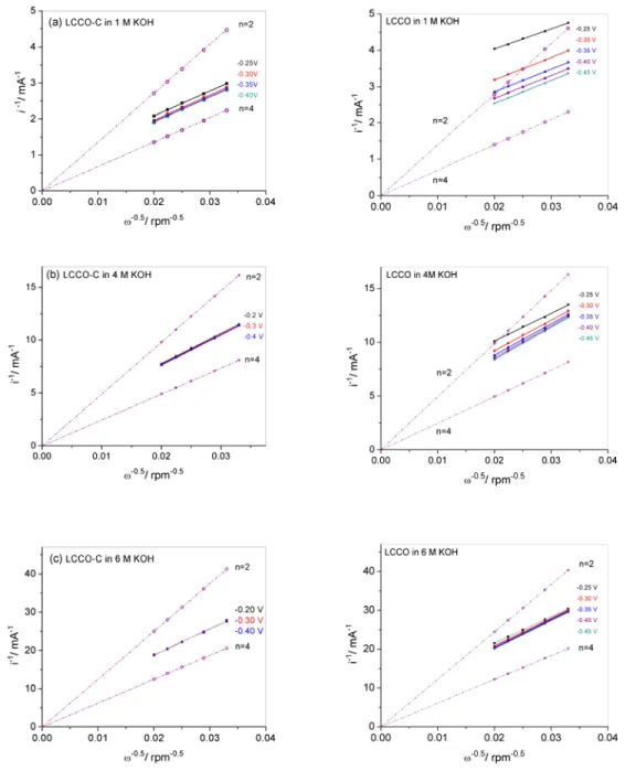
The disk I-V curves in Figure 4 consist of three ranges: the kinetics controlled range (low current range), the mixed kinetics and diffusion controlled range (middle current range), and the diffusion controlled range (plateau current range). Using Koutecky-Levich plots (i.e. rotating disk electrode theory) (19), both the ORR kinetics and diffusion processes can be analyzed. Figure 5 shows K-L plots for both LCCO and
LCCO-C electrodes in three KOH concentrations. According to K-L theory, if the reaction is assumed to be the first order with respect to the dissolved oxygen, the measured disk current (id, A) can be expressed as Equation [2] (20):
dl k d i i i 1 1 1 + = [2]
where ik and idl are the kinetic and diffusion-limiting currents, respectively. Furthermore, these ik and idl (both in an unit of A) can be expressed as Equations [3] and [4], respectively: 2 O k nFAkC i = [3] 2/3 1/6 1/2 1/2 2 2 20 . 0 nFAC D ν ω Bnω idl = O O − = [4]
where n is the overall electron transfer number in ORR, F is the Faraday constant (96500 C mol-1), A is the geometric area of the disk electrode (0.16 cm2),
2
O
C (mol cm-3) is the oxygen concentration dissolved in the electrolyte solution,
2
O
D (cm2 s-1) is the diffusion coefficient of oxygen , ν (cm2 s-1) is the kinematic viscosity of the electrolyte, ω (rpm) is the electrode rotation rate; k (cm s-1
) is the rate constant for O2 reduction reaction. In Figure 5, the theoretical K-L plots for the 2- and 4-electron transfer processes towards the ORR are also displayed in dash lines for comparison. These theoretical plots were calculated based on Equation (3) and the parameters reported in literature (21, 22). The corresponding values of B in Equation (3) and the theoretical slopes (1/Bn) for n=2 and n=4 in K-L plots were summarized in our recent work (13). It can be seen that all experimental plots show a linear and parallel feature at various potentials in 1, 4, and 6 M KOH for both two electrodes, confirming a first-order kinetics with respect to oxygen concentration (23). The slopes of the K-L plots were calculated close to the values of the theoretical 4-electron transfer lines on two electrodes in three concentrations, suggesting that the ORR process catalyzed by LCCO or LCCO-C are both dominated by a 4-electron transfer pathway.
It should be noted that there is a difference between the smooth electrode and the porous layer electrode when using RRDE technique for the kinetic evaluation. The major effect is the Nafion® layer thickness inside the porous layer, which can affect the diffusion of O2 within the electrode layer (24). To address this effect, Equation [2] may be expressed as Equation [5]: dl f k d i i i i 1 1 1 1 + + = [5]
where if is diffusion-limited current density within the Nafion® ionomer layer, which can be expressed as Equation [6]: 1 2 2 − =nFC D L i f O f O f [6]
where n and F have the same meanings as those in Equation (3), COf
2 and
f O
D
2are the
concentration and diffusion coefficient of O2 in the Nafion® layer, respectively, and L is the thickness of the Nafion® layer. In our experiments, the thickness of Nafion® ionomer layer is about 0.63 µm, as the density of Nafion film is 2 g cm-3 (25). Assuming the concentration and diffusion coefficient of oxygen in 117 Nafion layer is the same in acid
and alkaline media, if in Equation [6] was calculated to be 57 mA cm-2 according to the reported value of COf 2 and f O D 2in 1 M H2SO4 (26).
Figure 5. ORR Koutecky-Levich plots of LCCO-C (left) and LCCO (right) electrode in O2-saturated (a) 1 M, (b) 4 M, and (c) 6 M KOH solutions, respectively. The experiment conditions are the same as those in Figure 4.
In order to obtain the ORR kinetic constants in Equation (2), the K-L data was plotted at different electrode potential from –0.25 to –0.40V in three KOH concentrations, as shown in Figure 5. Each data group was extrapolated to ω-1/2=0 to obtain the intercept ( f k i i 1 1
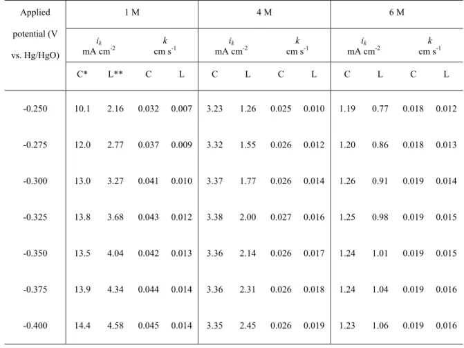
+ ), from which the ORR kinetic current densities (ik) and kinetic constants (k) were calculated and listed in Table 1. It can be seen that the values of ik and k are both
dependent on the electrode potentials, especially in lower alkaline concentrations. At all electrode potentials, the values of kinetic current densities and rate constants on LCCO-C electrode are higher than that on LCCO in all three concentrations. This result suggests that LCCO-C has a better catalytic performance towards ORR than LCCO and that the observed synergetic effect in the presence of carbon in the composite electrode layer might be one of the reasons.
Table 1 ORR kinetic currents ik (mA cm-2, corrected by accounting the effect of if) and rate constants k (cm s-1) on LCCO and LCCO-C electrodes at various potentials in O2 -saturated 1 M, 4 M and 6 M KOH solutions (ambient temperature and pressure).
Applied potential (V vs. Hg/HgO) 1 M 4 M 6 M ik mA cm-2 k cm s-1 ik mA cm-2 k cm s-1 ik mA cm-2 k cm s-1 C* L** C L C L C L C L C L -0.250 10.1 2.16 0.032 0.007 3.23 1.26 0.025 0.010 1.19 0.77 0.018 0.012 -0.275 12.0 2.77 0.037 0.009 3.32 1.55 0.026 0.012 1.20 0.86 0.018 0.013 -0.300 13.0 3.27 0.041 0.010 3.37 1.77 0.026 0.014 1.26 0.91 0.019 0.014 -0.325 13.8 3.68 0.043 0.012 3.38 2.00 0.027 0.016 1.25 0.98 0.019 0.015 -0.350 13.5 4.04 0.042 0.013 3.36 2.14 0.026 0.017 1.24 1.01 0.019 0.015 -0.375 13.9 4.34 0.044 0.014 3.36 2.31 0.026 0.018 1.24 1.04 0.019 0.016 -0.400 14.4 4.58 0.045 0.014 3.35 2.45 0.026 0.019 1.23 1.06 0.019 0.016
C* is composite electrode of LCCO-C L** is pure LCCO electrode
RRDE measurements to obtain ORR overall electron numbers
The overall electron number (n) of the ORR on both electrodes can be calculated from the ratio of disk and ring currents in RRDE measurements as well as from the K-L slopes. According to the RRDE theory, the overall electron transfer numbers and the corresponding mole percentage of H2O2 produced (mol% H2O2) in the ORR process can be determined using Equations [7] and [8], respectively (27, 28):
) / ( 4 N i i i n r d d + = [7]
N i i O H 100(r/ d) % 2 2 = [8]
Here, id is the current on the disk electrode, ir is the current on the ring electrode, and N is the collection efficient of ring electrode (=0.20±0.01). Based on Figure 4 as well as Equations [7] and [8], the overall electron transfer numbers in ORR process were calculated in potential range from –0.20 V to –0.50 V for the two electrodes at 2500 rpm in 1, 4, and 6 M KOH, as presented in Figure 6. It can be seen that the electron transfer numbers on LCCO-C and LCCO electrodes are in the range of 3.5-3.9 in the three alkaline solutions, which correspond to 3-14% of H2O2 production. The results are in good agreement to the results estimated from K-L plots in Figure 5.
Figure 6. ORR overall electron transfer numbers, obtained using RRDE electrodes coated with LCCO-C and LCCO separately in O2-saturated 1 M (black), 4 M (red), and 6 M (blue) KOH solutions. The electrode rotated at 2500 rpm. The experimental conditions were the same as displayed in Figure 4.
Conclusions
Perovskite La0.6Ca0.4CoO3 was successfully synthesized using a sol-gel method and characterized by XRD and BET. This LCCO material and its carbon composite (LCCO-C) were used to prepare the electrode layers for oxygen reduction reaction in 1,4, and 6 MKOH solutions. Both electrodes showed activities towards ORR but LCCO-C displayed a better activity than LCCO due to a synergetic effect in presence of carbon in the composite electrode layer. RRDE technique was used to quantitatively evaluate the ORR kinetics on both electrodes. Based on the experimental data, the ORR kinetic parameters, such as ORR overall electron transfer number, the ORR kinetic currents ik (corrected by accounting the effect of if) and kinetic rate constants k, were obtained using Kouteky-Levich analysis. The ORR processes catalyzed on these two materials are both 4-electron dominated transfer pathway to form the final product −
OH . LCCO-C was found to possess better catalytic performance towards ORR than LCCO, and the observed synergetic effect in the presence of carbon in the composite electrode layer was proposed to be one of the possible reasons.
Acknowledgements
This Project is financially supported by Program of Energy Research and Development (PERD) under Program at Objective Level (POL) 2.2.6, project C51.006, Canada.
References
1. H. Arai, S. Müller, O. Haas, J. Electrochem. Soc., 147 (10), 3584 (2000). 2. J. Goldstein, I. Brown, B. Koretz, J. Power Sources, 80, 171 (1999). 3. L. Swette, and J. Giner, J. Power Source, 22, 399 (1988).
4. L. Jörissen, J. Power Source, 155, 23 (2006).
5. J. Tulloch, and S. W. Donne, J. Power Sources, 188, 359 (2009).
6. S.W. Eom, S. Y. Ahn, C. W. Lee, Y. K. Sun, M. S. Yun, Solid state Phenomena,
124-126, 1055 (2007).
7. H. M. Zhang, N. Yamazoe, J. Mater. Sci. Lett., 8, 995 (1989).
8. T. Hyodo, M. Kayashi, N. Miura, N. Yamazoe, J. Electrochem. Soc., 143, L266 (1996).
9. V. Nikolova, P. Iliev, K. Petrov, T. Vitanov, E. Zhecheva, R. Stoyanova, I. Valov, D. Stoychev, J. Power Sources, 185, 727 (2008).
10. A. Weidenkaff, S. G. Ebbinghaus, T. Lippert, Chem. Mater. 14, 1797 (2002). 11. S. Muller, K. Striebel, O. Haas, Eletrochim. Acta, 39, 1661 (1994).
12. C. K. Lee, K. A. Striebel, F. R. McLarnon, E. J. Cairns, J. Electrochem. Soc., 144
(11), 3801 (1997).
13. X. X Li, W. Qu, H. J. Wang, R. Hui, L. Zhang, J. J. Zhang, in press in Electrochim. Acta, doi:10.1016/j.electacta.2010.05.041.
14. V. Radmilovic, H. A. Gasteiger, P. N. Ross, J. Catal., 154, 98 (1995).
15. M. H. Miles, Y. H. Huang, S. Srinivasan, J. Electrochem. Soc., 125, 1931 (1978). 16. V. Hermann, D. Dutriat, S. Müller, Ch. Comninellis, Electrochim. Acta, 46, 365
(2000).
18. K. E. Gubbins, R. D. Walker, J. Electrochem. Soc., 112, 469 (1965).
19. A. J. Bard, L. R. Faulkner, Electrochemical Methods: Fundamentals and Applications, 2nd ed., John Wiley & Sons, New York, 2001.
20. R. R. Adzić, N.M. Marković, V. B. Vesović, J. Electroanal. Chem., 165, 105 (1984). 21. K. E. Gubbins, and R. D. Walker, J. Electrochem. Soc., 112, 469 (1965).
22. D. R. Lide (Ed.), CRC Handbook of Chemistry and Physics, CRC Press, the content of the 90th Edition, 2009-2010.
23. H. Meng, and P. K. Shen, Electrochem. Comm., 8, 588 (2006).
24. T. J. Schnidt and H. A. Gasteiger, Chapter 22, in Handbook of Fuel Cells, Fundamentals, Technology, and Applications, Vol. 2 (Electrocatalysis), edited by W. Vielstich, A. Lamm, and H. A. Gasteiger, Wiley, 2003.
25. O. A. Baturina, and G. E. Wnek, Electrochem. Solid-State Lett., , 8 (6), A267 (2005). 26. A. T. Haug, and R. E. White, J. Electrochem. Soc., 147 (3), 980 (2000).
27. C. B. Bezerra, L. Zhang, K. C. Lee, H. S. Liu, J. L. Zhang, Z. Shi, A. L. B. Marques, E. P. Marques, S. H. Wu, J. J. Zhang, Electrochim. Acta, 53, 7703 (2008).
28. U. A. Paulus, T. J. Schmidt, H. A. Gasteiger, R.J. Behm, J. Electroanal. Chem., 495, 134 (2001).