Publisher’s version / Version de l'éditeur:
Journal of Building Enclosure Design, pp. 15-18, 2011-07-01
READ THESE TERMS AND CONDITIONS CAREFULLY BEFORE USING THIS WEBSITE. https://nrc-publications.canada.ca/eng/copyright
Vous avez des questions? Nous pouvons vous aider. Pour communiquer directement avec un auteur, consultez la
première page de la revue dans laquelle son article a été publié afin de trouver ses coordonnées. Si vous n’arrivez pas à les repérer, communiquez avec nous à PublicationsArchive-ArchivesPublications@nrc-cnrc.gc.ca.
Questions? Contact the NRC Publications Archive team at
PublicationsArchive-ArchivesPublications@nrc-cnrc.gc.ca. If you wish to email the authors directly, please see the first page of the publication for their contact information.
NRC Publications Archive
Archives des publications du CNRC
This publication could be one of several versions: author’s original, accepted manuscript or the publisher’s version. / La version de cette publication peut être l’une des suivantes : la version prépublication de l’auteur, la version acceptée du manuscrit ou la version de l’éditeur.
Access and use of this website and the material on it are subject to the Terms and Conditions set forth at
An experimental procedure to quantify air intrusion in commercial
roofing systems
Molleti, S.; Baskaran, B. A.
https://publications-cnrc.canada.ca/fra/droits
L’accès à ce site Web et l’utilisation de son contenu sont assujettis aux conditions présentées dans le site LISEZ CES CONDITIONS ATTENTIVEMENT AVANT D’UTILISER CE SITE WEB.
NRC Publications Record / Notice d'Archives des publications de CNRC: https://nrc-publications.canada.ca/eng/view/object/?id=7b7c5ae3-6165-4ff9-bb19-f2dede3f5beb https://publications-cnrc.canada.ca/fra/voir/objet/?id=7b7c5ae3-6165-4ff9-bb19-f2dede3f5beb
An Experimental Procedure to
Quantify Air Intrusion in
Commercial Roofing Systems
N R C C - 5 4 4 6 0
M o l l e t i , S . ; B a s k a r a n , B . A
J u l y 2 0 1 1
A version of this document is published in / Une version de ce document se trouve dans:
Journal of Building Enclosure Design, Summer 2011 (www.wbdg.org/pdfs/jbed_summer11.pdf) http://www.nrc-cnrc.gc.ca/irc
The material in this document is covered by the provisions of the Copyright Act, by Canadian laws, policies, regulations and international agreements. Such provisions serve to identify the information source and, in specific instances, to prohibit reproduction of materials without written permission. For more information visit http://laws.justice.gc.ca/en/showtdm/cs/C-42
Les renseignements dans ce document sont protégés par la Loi sur le droit d'auteur, par les lois, les politiques et les règlements du Canada et des accords internationaux. Ces dispositions permettent d'identifier la source de l'information et, dans certains cas, d'interdire la copie de documents sans permission écrite. Pour obtenir de plus amples renseignements : http://lois.justice.gc.ca/fr/showtdm/cs/C-42
Page 1 of 8
An Experimental Procedure to Quantify Air Intrusion in Commercial Roofing
Systems
Suda Molleti and Bas Baskaran
National Research Council Canada 1200 Montreal Road, Campus-Building M-24, Ottawa, Ontario K1A 0R6, Canada Introduction
The commercial buildings encompasses hospitals, schools, offices, lodging, and the retail sector with its big box stores, enclosed malls, strip malls, grocery stores and fast food restaurants Approximately one fourth of North American commercial buildings are roofed with Flexible Roof Systems (FRS) (NRCA 2004). In FRS, the waterproofing membrane is on the top exposed to the environmental forces with other roofing components such as insulation and cover board below it integrated to the structural substrate using mechanical fasteners. Field observations have identified that air intrusion in mechanically attached roof systems can affect roof system performance. However, the question of how much air movement occurs and which components provide the required resistance to air movement has never been addressed. To measure air intrusion in mechanically attached roof systems, an experimental study is recently completed at the National Research Council (NRC) of Canada as part of its Special Interest Group for Dynamic Evaluation of Roofing Systems (SIGDERS) research.
What is Air Intrusion?
In FRS, the waterproofing membrane is available in three different types: Modified bituminous (Mod-Bit), Thermoplastic [polyvinyl chloride (PVC) and thermoplastic olefin (TPO)] and Thermoset [ethylene propylene diene terpolymer [EPDM]). The Mod-Bit is asphaltic based and comprises of two ply membranes- base and cap sheet, which on integrating as a roof system performs as a one ply membrane. Both the base and cap sheets come in standard width of 3ft. The thermosets and thermoplastics are single ply membranes composed predominately of synthetic polymer. These are strong, flexible sheets with thickness in the range 45 mil to 80 mil. All the membranes are sealed at joints or overlaps to form continuous waterproofing. Both these membranes are available in different sheet widths ranging from 6 ft to 12 ft.
The waterproofing membranes, material wise are inherently impermeable to air and if constructed properly as a system, they can certainly perform as an air barrier impeding any air leakage from the exterior environment to the interior and vice versa. Therefore, the water proofing membrane can be designated as the air barrier to control air leakage (Kalinger 2008). However, the flexibility and elastic nature of membranes and their discrete fastener attachment
Page 2 of 8
mechanisms, can cause membrane ballooning or fluttering due to wind induced suctions and interior mechanical pressurization. The volume change of the membrane ballooning causes negative or bubble pressure below the membrane, which is equalized by the indoor conditioned air moving into the system, and this is termed as ―air intrusion (Figure 1): when the conditioned
indoor air enters into a building envelope assembly, such as roofs, but cannot leave the assembly to exterior environment” (Molleti 2009). The pressure equalization depends on the air
intrusion resistance of the components below the membrane (insulation, deck and other).
What are the effects of Air Intrusion?
Cautions regarding air intrusion are not new (Dregger 2002). There are existing technical notes, manuals and papers that have identified how air intrusion affects roof assembly performance. However, no information is available regarding the amount of air intrusion that can occur in mechanically attached roof systems and their sensitivity to air movement.
The wind-uplift resistance of a mechanically attached roof system depends on the membrane’s response to wind dynamics. Fluttering during wind action creates a region of low pressure below the membrane. To equalize the pressure, indoor air intrudes into the system. If the roof components below the membrane do not provide sufficient resistance to air intrusion and the rate of air intrusion is rapid, the combination of the positive and negative uplift forces on the membrane, which resists the entire uplift load, could lead to the failure of the membrane and system. This is illustrated in Figure 2.
Apart from diffusion, which causes water vapor transportation into roof systems, the other significant mechanism of moisture entry into a roof system from a building’s interior is air intrusion. Dew point temperature can occur below the membrane and within the insulation. When warm humid air--which can hold a high quantity of water vapor--is drawn into a roof assembly and contacts surfaces materials at the dew point temperature it condenses as shown in Figure 2. Condensation can lead to wet insulation, which will reduce its thermal performance and affect the roof assembly’s energy performance.
How to Quantify Air Intrusion?
To measure air intrusion in flexible roof systems, an experimental study is recently completed at the National Research Council (NRC) of Canada as part of its Special Interest Group for
Page 3 of 8
Dynamic Evaluation of Roofing Systems (SIGDERS) research. Since 1994, SIGDERS did a pioneering research work on the wind uplift performance of flexible roofing systems, which led to the development of a technical guide ―A Guide for the mechanically attached flexible membrane roofs‖ and national standard CSA A123-21-10 ―Standard test method for the dynamic wind uplift resistance of membrane-roofing systems‖. As part of this on-going research work, air intrusion quantification was determined to be an influential parameter on the performance of flexible roofing systems, and SIGDERS focussed on determining control data for air intrusion in these roofing systems.
Air intrusion involves volumetric measurements, which is technically different from the air leakage. Similar to air leakage, a differential pressure and flow path is required for air intrusion, however the air intrusion measured is the volumetric flow into the flexible roofing system. To quantify the volumetric flow, a new test laboratory was developed at the NRC - Dynamic Roofing Facility for Air Intrusion Quantification (DRF-AI).The test apparatus is shown in Figure 3. It is composed of a movable two-section top chamber and closed bottom chamber; each has a dimension of 20 feet by 8 feet by 3 feet. The test consists of installing a roof specimen between the two chambers, prescribed suction pressures in the range of 5 psf to 25 psf in increments of 5 psf are applied across the system in the top chamber through a controllable blower, while the resultant air intrusion into the system is measured from the airflow measurement system installed on the air tight bottom chamber. The bottom chamber supports a height- adjustable lever that can accommodate roofing assemblies with different thicknesses. The differential pressure across the test specimen is measured by installing two pressure measuring devices, one on top of the membrane and the other above the insulation.
The above experimental method recently became an ASTM standard – D7586/D7586M-11 Standard Test Method for Quantification of Air Intrusion in Low-Sloped Mechanically Attached Membrane Roof Assemblies. This test method is intended to measure only air intrusion associated with the opaque roof assembly free from penetrations such as those associated with mechanical devices, roof junctions, and terminations.
How the Control Data was Developed?
Towards developing control data for the flexible roofing systems, series of tests were conducted following the ASTM D7586. Three types of roof systems—polymer-modified bitumen (MB), thermoplastic (TP) and thermoset (TS)--were tested. Within each type, roof configurations with
Page 4 of 8
and without air barrier, and with staggered insulation were tested. Apart from the membrane type and installation, all other roof components were similar, which comprised of: 22-gauge, 80-ksi steel deck; for one layer insulation systems: 48 by 48 by 2-inch polyisocyanurate insulation boards fastened with five fasteners per board, and 3 mil thick self-adhering film as an air retarder for the specimens with air retarders.
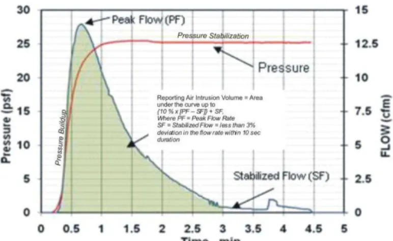
Following the ASTM D7586 test protocol, the analysis of the measured data involves plotting the relation between air flow and applied pressure. Figure 4 shows a typical air intrusion measured data for a flexible roofing system without air retarder at the test pressure of 25 psf. Integrating the area under the measured air flow quantifies air intrusion of the roofing system at that pressure level. For relative comparison among the tested systems, the ASTM D7586 selects a reference test pressure of 25 psf for reporting the air intrusion volume per linear length [ft3 / ft] as shown in Figure 4.
Air intrusion data for the ten tested systems shown in Figure 5 not only defines the control data but also identifies the influencing parameters on the air intrusion performance of FRS. Sheet width could be said as one of the significant parameters for air intrusion. The experimental study evaluated three sheet widths: 3, 6 and 10 ft , and of the three, the roofing system with 3 ft sheet had minimum air intrusion, and with the increase in the sheet width to 6 ft and 10 ft the air intrusion volume was measured to be almost three times higher compared to the smaller sheet of 3 ft. Although the air intrusion and the sheet width might not show a linear relationship, the data indicates that with the increase in the bubble volume the air intrusion into the roof system increases. The data also shows that the membrane material type is not a major contributor compared with the bubble volume. Both the 10 ft thermoset and thermoplastic membranes were reinforced, and with all similar roof system components, the thermoset system showed a 10% higher air intrusion compared to the same width thermoplastic system.
Air retarder is an element in the roof system intended to limit air flow. For the control data testing, a bituminous modified reinforced self adhered film was installed as an air retarder on the steel deck for all the three tested systems. The air retarder had two overlaps in the system layout and it underwent fastener penetrations from the installation of insulation and membrane. Relative performance indicates that the air intrusion rate reduced 50 percent in the 3-foot polymer-modified bitumen systems, about 75 percent in the 6-foot thermoplastic systems and about 85 percent in the 10-foot thermoset systems compared with systems without air retarders. The air intrusion volume of the three assemblies is almost similar with an average air intrusion
Page 5 of 8
volume of 0.36 ft3/linear ft, indicating that irrespective of the system type and configuration, the presence of an air retarder at deck level, if constructed properly, minimizes air intrusion.
How Much Air Intrusion is too Much?
Research conducted at NRC for the SIGDERS consortium has demonstrated the wind-uplift resistance of mechanically attached roof systems can be increased as much as 50 percent by including an air retarder regardless of the air retarder type (Baskaran et.al. 2003). This finding can be justified from the measured air intrusion data. The air intrusion reduction is what differentiates the wind-uplift performance of assemblies with and without air retarders.
ASHRAE 189.1, ―Standard for the Design of High-Performance, Green Buildings except Low-Rise Residential Buildings,‖ provides guidelines for the use and design of air barriers in roof assemblies. It accepts fully adhered single ply membrane systems as continuous air barriers but not the mechanically attached single-ply membrane roof systems. The rationale behind this assumption could be that the single-ply membrane undergoes fluttering action thereby not meeting the air barrier requirement of structural strength. It should be understood that the primary function of roofing membrane is waterproofing, and as it successfully performs its intended function by sustaining high wind uplift pressures, it certainly performs as an air barrier. Due its inherent flexibility nature the membrane undergoes fluttering or billowing during wind action, but that doesn’t affect its membrane porosity or its integrity with the system. This can be verified from Figure 4. During the pressure buildup to a target of 25 psf, the air intrudes into the system illustrated by the peak flow, and once the pressure stabilizes the flow does not stabilize but the flow rate is gradually reduced. Had the roofing membrane been permeable or its continuous joints not air tight, the flow rather than gradually descending would have stabilized with pressure stabilization. In flexible roofing systems rather than contemplating on the issue of air barrier and air leakage, code requirements should be focused on air intrusion.
Good design practice tells us to prevent the movement of moisture-laden air into roof assemblies, which can be achieved by installing a continuous air retarder at the deck level. However, complete air tightness can lead to trapped vapor between two impermeable air retarders. To determine the limits of air intrusion for building code recommendations and quantify air intrusion’s effect on condensation control and energy performance, further research is being conducted in collaboration with NRCA and CRCA.
Page 6 of 8 References
American Society of Testing Materials-ASTM D7586 D7586/D7586M-2011, ―Standard Test Method for Quantification of Air Intrusion in Low-Sloped Mechanically Attached Membrane Roof Assemblies‖.
Baskaran A., Smith T.L., (2005). ―A guide for the wind design of mechanically attached flexible membrane roofs‖, National Research Council Canada, Ottawa, Ontario, Canada
Baskaran, B.A., Molleti, S., Sexton, M.(2003). "Wind uplift performance of roofing systems with vapour barrier," 9th Canadian Conference on Building Science and Technology (Vancouver, B.C., February 27, 2003), pp. 349-364, February 01.
CSA Number A123.21-10 (2010),‖Standard test method for the dynamic wind uplift resistance of membrane-roofing systems‖, Canadian Standards Association, Canada.
Dregger, P., ―Air Infiltration–The Enemy of Wind Resistance & Condensation Control‖, RCI Interface, June 2002.
Kalinger, P., ― The Roof as an Air Barrier,‖ Proceedings of the RCI 23rd International Convention & Trade Show - February 28 - March 4, 2008, Phoenix, Arizona
Molleti, S.; Baskaran, B.A.; Ko, K.P.; Beaulieu, P. "Air intrusion vs. air leakage - the dilemma for low sloped mechanically attached membrane roofs," Proceedings of the Canadian Symposium on Roofing Technology, Toronto, March, 2009, pp. 1-9.
National Roofing Contractors Association. 2004. ―Hurricane Charley: A Preliminary Report‖,
Page 7 of 8
FIGURE 1: CONCEPT OF AIR INTRUSION
(a) Wind Uplift Resistance (b) Condensation
FIGURE 2: AIR INTRUSION IMPACTS ON THE LIFE CYCLE PERFORMANCE OF FRS
Page 8 of 8
FIGURE 4: TYPICAL TIME HISTORY PLOT OF THE AIR INTRUSION DATA AND THE REPORTING AIR INTRUSION CALCULATION