Publisher’s version / Version de l'éditeur:
Journal of ASTM International, 6, 8, p. 14, 2009-08-03
READ THESE TERMS AND CONDITIONS CAREFULLY BEFORE USING THIS WEBSITE.
https://nrc-publications.canada.ca/eng/copyright
Vous avez des questions? Nous pouvons vous aider. Pour communiquer directement avec un auteur, consultez la
première page de la revue dans laquelle son article a été publié afin de trouver ses coordonnées. Si vous n’arrivez pas à les repérer, communiquez avec nous à PublicationsArchive-ArchivesPublications@nrc-cnrc.gc.ca.
Questions? Contact the NRC Publications Archive team at
PublicationsArchive-ArchivesPublications@nrc-cnrc.gc.ca. If you wish to email the authors directly, please see the first page of the publication for their contact information.
Archives des publications du CNRC
This publication could be one of several versions: author’s original, accepted manuscript or the publisher’s version. / La version de cette publication peut être l’une des suivantes : la version prépublication de l’auteur, la version acceptée du manuscrit ou la version de l’éditeur.
For the publisher’s version, please access the DOI link below./ Pour consulter la version de l’éditeur, utilisez le lien DOI ci-dessous.
https://doi.org/10.1520/JAI102087
Access and use of this website and the material on it are subject to the Terms and Conditions set forth at Role of vapor barrier in wood-frame stucco wall in various North American climates - observations from hygrothermal simulation
Mukhopadhyaya, P.; Ping, F.; Kumaran, M. K.; Van Reenen, D.
https://publications-cnrc.canada.ca/fra/droits
L’accès à ce site Web et l’utilisation de son contenu sont assujettis aux conditions présentées dans le site LISEZ CES CONDITIONS ATTENTIVEMENT AVANT D’UTILISER CE SITE WEB.
NRC Publications Record / Notice d'Archives des publications de CNRC: https://nrc-publications.canada.ca/eng/view/object/?id=67ec7226-70e3-4e2c-a2a2-4778daf863ee https://publications-cnrc.canada.ca/fra/voir/objet/?id=67ec7226-70e3-4e2c-a2a2-4778daf863ee
Role of va por ba rrie r in w ood-fra m e st uc c o w a ll in va rious N ort h Am e ric a n c lim a t e s - obse rva t ions from hygrot he rm a l sim ula t ion
N R C C - 5 1 4 0 6
M u k h o p a d h y a y a , P . ; P i n g , F . ; K u m a r a n , M . K . ; V a n R e e n e n , D .
A u g u s t 2 0 0 9
A version of this document is published in / Une version de ce document se trouve dans: Journal of ASTM International, 6, (8), pp. 14, August 03, 2009, DOI:
10.1520/JAI102087
The material in this document is covered by the provisions of the Copyright Act, by Canadian laws, policies, regulations and international agreements. Such provisions serve to identify the information source and, in specific instances, to prohibit reproduction of materials without written permission. For more information visit http://laws.justice.gc.ca/en/showtdm/cs/C-42
Les renseignements dans ce document sont protégés par la Loi sur le droit d'auteur, par les lois, les politiques et les règlements du Canada et des accords internationaux. Ces dispositions permettent d'identifier la source de l'information et, dans certains cas, d'interdire la copie de documents sans permission écrite. Pour obtenir de plus amples renseignements : http://lois.justice.gc.ca/fr/showtdm/cs/C-42
Role of Vapor Barrier in Wood-Frame Stucco Wall in
Various North American Climates – Observations
from Hygrothermal Simulation
ABSTRACT: This paper investigates the role of the vapor barrier in exterior wood-frame stucco walls with the help of a two dimensional hygrothermal simulation tool, hygIRC-2D. For this purpose, the wall is subjected to the exterior weather conditions of six different North American geographic locations and three different interior climatic conditions. Seven different vapor diffusion strategies, generated by varying the water vapor permeance of the vapor barrier, installed outboard of the interior finish, have been studied to generate critical understanding on the role of vapor barrier in the wood-frame stucco walls.
The outputs from the simulations have been analyzed with the help of a novel moisture response indicator called RHT index. Simulation results indicate that the vapor transmission characteristics of the vapor barrier, in terms of water vapor permeance, play a very important role in the overall moisture response of the wood-frame stucco wall. A very high or low vapor permeance of the vapor barrier does not produce the optimum moisture management strategy for the wood-frame stucco wall. Moreover, simulation results indicate that the removal of vapor barrier from the wall system can result in a heightened moisture response and a considerable accumulation of moisture in the interior gypsum board that may lead to severe consequences in particular, the premature deterioration of the interior facing gypsum board. It has also been observed from the simulation outputs that the optimum vapor diffusion strategy, that of limiting the vapor permeance of the vapor barrier, is not a function of interior climatic conditions considered in this study.
It is hoped that the results reported in this paper will shed some light on a number of concerns raised in recent years on the role of vapor barrier in wood-frame stucco wall construction.
KEYWORDS: vapor barrier, water vapor permeance, wood-frame stucco wall, exterior climate
1
Associate Research Officer, Institute for Research in Construction, National Research Council Canada, Ottawa, ON, K1A OR6.
2
Associate Professor, Hunan University, China. 3
Principal Research Officer, Institute for Research in Construction, National Research Council Canada, Ottawa, ON, K1A OR6.
4
Technical Officer, Institute for Research in Construction, National Research Council Canada, Ottawa, ON, K1A OR6.
Introduction
The moisture management performance of exterior walls in a building envelope is very critical for its long-term durability and serviceability. However, moisture design of a building envelope is a complex task by any standard. The functional variation, focus on energy efficient building envelope design, presence of different ventilation systems and use of new materials in construction have all contributed to this complexity. The moisture management capability of an exterior wall is heavily dependent on the water vapor diffusion characteristics of the wall components and without a proper vapor diffusion control strategy; the short and long-term performance or durability of the wall can be seriously compromised.
In addition to moisture carried by air leakage, moisture in the form of water vapor diffuses through the wall assembly due to water vapor pressure and/or temperature gradient across the wall cross section. The direction of water vapor movement depends on the exterior climate and indoor environment. During the heating season (i.e. winter) moisture primarily migrates toward the exterior face of the building envelope and during the cooling season (i.e. summer) moisture primarily moves towards the inside of the building envelope. Condensation of this moisture inside the wall assembly is highly undesirable as it may lead to premature deterioration of the wall component on which it is deposited.
Water vapor condensation can occur when moisture is free to migrate into the building envelope and move into colder areas with a temperature below the dew point. The role of the vapor barrier in the wall assembly is to limit the moisture movement from the warmer part of the wall assembly to the colder part of the wall. For this precise reason, it is a requirement in the National Building Code (NBC) of Canada (2005) [1] to install a vapor barrier on the warmer side of the insulation. However in real life the colder side of the insulation is not always static, particularly in geographical locations with wide fluctuating weather conditions.
The role of the vapor barrier in building envelope construction is an issue that has been investigated and debated in North America for over sixty years [2-5]. The complexity of the issue and the lack of definitive research mean, that for many smaller low-rise buildings, moisture diffusion continues to be governed by simple prescriptive requirements that are not particularly case-sensitive. Water vapor permeance for vapor barriers in these buildings, determined by ASTM Standard E96/E96M-05, Test Methods for Water Vapor Transmission of Materials, desiccant method (dry cup), must not exceed 60 ng/(Pa.s.m2). For other buildings where professionals are expected to be involved in the design, the National Building Code of Canada (2005) [1] provides more general performance-based requirements that allow for greater case-sensitivity. Although there is no evidence of problems as a result of compliance with the NBC prescriptive requirements, questions remain regarding the specific limits prescribed. However, the exact influence of these prescriptive values on the overall moisture response of the wall due to climatic moisture load is still not very clear. Experimental data are needed to critically examine this issue but such experiments are time consuming, expensive and on occasions practically difficult to perform. In such a situation, the use of computer aided numerical modeling can be a realistic scientific option. However, this option is only useful if the model is benchmarked. The study reported in this paper uses a two-dimensional (2-D) modeling tool, hygIRC-2D, to assess the effect of water vapor
permeance characteristics of the vapor barrier on the overall moisture response of a wood-frame stucco wall exposed to various exterior and interior climatic conditions in North America.
Research Background
A two-dimensional numerical modeling study, carried out by Karagiozis and Kumaran [6], opened up a discussion on the necessity of specific water vapor permeance characteristics of the vapor barrier, as prescribed in the National Building Code of Canada (1990) [7], installed at the interior side of the wall assembly in different geographic locations to achieve optimum moisture management. The results from this study indicated the necessity of location specific water vapor permeance values for the vapor barrier. It was also suggested that it might not be necessary to install a vapor barrier for a wall built in Vancouver, Canada. However, these studies were done using constant interior boundary conditions (20°C and 38.5% relative humidity) and the presence of exterior cladding was not modeled. Moreover, the study neglected entirely the effect of driving rain, solar radiation and wind velocity on the water vapor movement through the wall assembly.
Further to the aforementioned study, Mukhopadhyaya et al. [8] conducted a number of simulations for wood-frame stucco walls for locations of Ottawa and Vancouver, using a more advanced two dimensional modeling tool that takes into account the effect of driving rain, solar radiation, wind velocity and also the presence of exterior cladding. A single interior boundary condition was assumed to be variable and functionally related to the exterior climate. The results from this simulation study indicated that a vapor barrier having a higher water vapor permeance results in greater drying and wetting of the wall assembly in terms of total moisture content. This study did not look into the localized moisture response of the wall assembly.
A more recent study by Mukhopadhyaya et al. [9], using advanced two dimensional modeling tool, found that very high or low vapor permeance of the vapor barrier did not produce the optimum moisture management strategy for the wood-frame stucco wall subjected to a climate as exists in Vancouver, Canada. Moreover, simulation results indicated that the removal of vapor barrier from the wall system could result in a heightened moisture response and a considerable accumulation of moisture in the interior gypsum board. It was also observed that the optimum vapor diffusion strategy, that of limiting the vapor permeance of the vapor barrier, is not a function of three different interior climatic conditions considered in this study.
This paper is a logical extension of the aforementioned studies and investigates, using an advanced two dimensional modeling tool, the role of seven different vapor diffusion strategies for moisture management in a wood-frame stucco wall assembly exposed to three different interior boundary conditions and six exterior North American climatic conditions. It is hoped that this paper will address many queries regarding the use of vapor barrier in the wood-frame stucco wall assemblies in various North American climatic conditions.
hygIRC-2D and Input for Simulation
The computer aided numerical tool used in this study is hygIRC-2D that can predict the moisture response of building envelopes [10]. hygIRC-2D is a benchmarked modeling
tool [11,12] for hygrothermal simulation. hygIRC-2D accommodates many advanced features, such as transient heat, air and moisture (liquid and vapor) transport, 2 -dimensional spatial formulation, variable material properties with moisture content and temperature, air flow through building materials, effect of solar radiation, presence of moisture source inside the material, freezing-thawing effect, as well as other useful features [13,14].
hygIRC-2D has a pre-processor that allows the user to divide a wall into a number of
layers, both in the horizontal and vertical directions. Using this tool a wall-section can be divided into several layers to accommodate its material and geometrical specifications and specific construction details. Each of these layers is ‘meshed’ into rectangular elements by dividing each layer horizontally and vertically. The pre-processor allows the division of each layer into a number of elements that can be each of equal size or either expanded or contracted towards the boundary or centre, as specified by the user, according to designated stretching factor. This provision helps to obtain more efficient solutions derived from numerical modeling, by selecting an optimum number of elements for the model. However, the effective use of such type of advanced numerical tools to analyze and obtain meaningful results demands both the proper physical understanding of the problem, appropriate definition of input parameters and the ability to judiciously interpret the results [15-17].
There are a number of major input parameters required for hygIRC-2D simulation and they are:
1. Basic wall construction details, 2. Material properties,
3. Boundary conditions, 4. Exposure duration, and
5. Initial moisture content and temperature.
These major input parameters are described in the following paragraphs. Basic Wall Construction Details
The basic wall construction details which was used for all the parametric studies is shown in Fig. 1.
Material Properties
The materials used for the wall construction are: (1) Lime stucco; (2) Sheathing membrane; (3) Oriented strand board (OSB); (4) Glass fiber; (5) Spruce; (6) Vapor barrier; (7) Gypsum board; and (8) Paint coated gypsum board.
The material properties used for simulations were taken from the IRC material property database [18,19]. These properties were carefully determined in the Insulation and Building Materials Laboratory of the National Research Council (NRC) Canada - Institute for Research in Construction (IRC) following the standard test procedures [19].
The eight distinct sets of material properties required for hygIRC-2D simulation are: (i) Air permeability (m2) in the X and Y-direction
(ii) Thermal conductivity (W m-1 K-1) in the X and Y-direction (iii) Dry density (kg m-3)
(iv) Heat capacity (J K-1 kg-1)
(v) Sorption characteristics (i.e. change of moisture content with relative humidity) (kg water kg-1 dry weight)
(vi) Suction pressure (Pa)
(vii) Water vapor permeability (kg m-1 s-1 Pa-1) in the X and Y-direction (viii) Liquid diffusivity (m2 s-1) in the X and Y-direction
Boundary Conditions
The two boundary conditions required for hygIRC-2D simulation are the interior condition and the exterior condition.
Recorded weather data are used for the exterior condition. The seven components of the weather data are: (1) Temperature, (2) Relative Humidity, (3) Wind Velocity, (4) Wind Direction, (5) Radiation (Direct, Diffused and Reflective components), (6) Horizontal rainfall, and (7) Cloud index.
The interior boundary conditions considered are the indoor temperature (T) and the indoor relative humidity (RH).
Exposure Duration
A total duration of two years (same year5 repeated) of exposure is considered in this study.
Initial Moisture Content and Temperature
It is assumed in this study that the initial moisture content of each wall component is equivalent to the corresponding relative humidity of 50%, derived from the sorption isotherm of the respective materials. The initial temperature across the entire wall cross- section is assumed to be 20°C.
Parametric Study
In this study the role of the vapor barrier in wood-frame stucco wall assemblies is examined in six North American cities with three different indoor conditions.
Six cities, spreading all over North America (Fig. 2), selected for this study are Winnipeg (MB, Canada), Ottawa (ON, Canada), Halifax (NS, Canada), Vancouver (BC, Canada), Phoenix (AZ, USA), and Wilmington (NC, USA). The weather patterns of these six cities are very different from each other. From the overall characteristics, the climates of these six locations can be described as: Winnipeg – cold and dry; Ottawa – cold and humid; Halifax – cold and humid (warmer and wetter than Ottawa); Vancouver – marine; Phoenix – hot and dry; and Wilmington – warm and humid [20].
5
Winnipeg – 1978, Ottawa – 1959, Phoenix – 1972, Halifax – 1980, Wilmington – 1977, Vancouver - 1969
Three different indoor conditions are considered in this study and they are aimed to represent three realistic scenarios for the interior temperature and relative humidity, as outlined below.
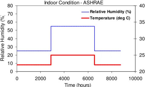
(i) Constant 40% relative humidity (RH) and 22°C temperature (T) condition, (ii) Controlled indoor condition (RH and T) according to ASHRAE Application
Handbook, Chapter 3 [21]. Fig. 3a shows an example of controlled indoor conditions in Vancouver according to ASHRAE guidelines. In this study the summer and winter seasons are identified according to the criteria specified in the 'Specifications to National (Canada) Energy Code for Houses', [22] as follows: Winter - Mean monthly outdoor temperature < 11ºC, and, Summer - Mean monthly outdoor temperature > 11ºC.
(iii) Indoor climatic conditions that are generated from outdoor climatic data using the weather analysis tool Weathersmart [23], developed at the NRC-IRC. In this particular case, the indoor RH conditions have been derived using a model proposed by Jones [24] with the indoor temperature 21°C (both for summer and winter), moisture load 7.5 liter/day, air leakage 1.44 cm2/m2, volume 192 m3, air exchange rate (ACH) 0.3, and indoor maximum RH cap of 75%. An example of indoor conditions at Vancouver, generated by Weathersmart, is shown in Fig. 3b. Similarly indoor conditions are also derived for other five geographic locations.
Seven cases of different vapor resistances, offered by the vapor barrier and interior gypsum board, have been evaluated in this study. The gypsum board, considered in this study, is coated with primer and latex paint. An uncoated gypsum board, with no vapor barrier, is also evaluated. The total vapor permeance values of the vapor barrier and interior gypsum board, considered in this study, vary between 14.7 ng/m2.s.Pa and 2753.3 ng/m2.s.Pa (Table 1).
A summary of all the parametric variations considered in this study is shown in Table 1.
hygIRC-2D Output and Analysis of Results
A significant amount of data have been generated from hygIRC-2D and subsequently post-processed for the detailed evaluation of the simulated hygrothermal response of the various walls through parametric analyses. The results obtained from the typical
hygIRC-2D output have been further analyzed as described in the following paragraphs.
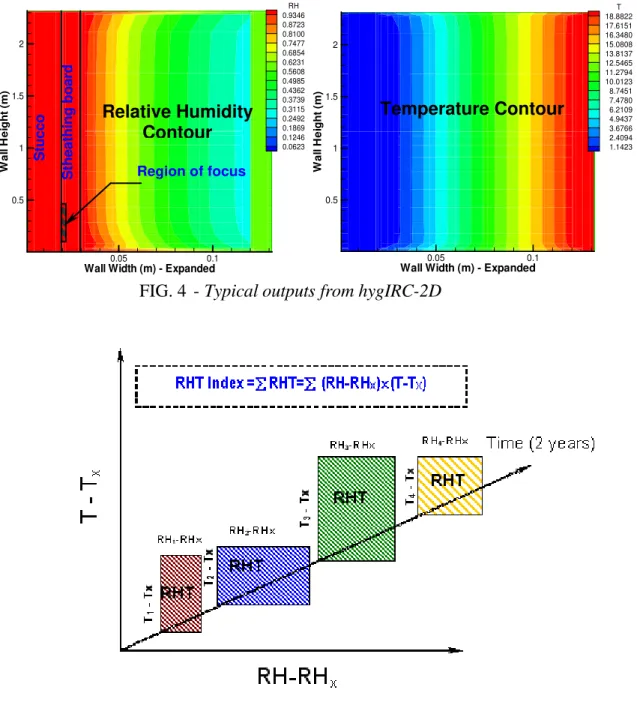
Typical hygIRC-2D Output
The basic outputs from hygIRC-2D simulations are the relative humidity (RH) and temperature (T) contour plots (Fig. 4) across the wall assembly cross-section (vertical). In this study, these contour plots were generated at midnight, at every 10-day interval for the entire duration of the simulation/exposure period (i.e. 2 years). In order to make quantitative sense of the long-term moisture response of the wall assembly from these outputs, a novel hygrothermal performance indicator called RHT index, derived from the RH and T distribution patterns over a period time as defined in the following paragraphs, has been used.
RHT Index - Hygrothermal Response Indicator
It is widely accepted that building materials are subject to deterioration under the combined effects of temperature and moisture. The most deleterious conditions are those in which moderate or high temperature is coupled with high humidity for extended periods [25]. This study uses a novel long-term hygrothermal response indicator, called the RHT index [26-28], derived from the relative humidity (RH) and temperature (T) conditions inside the building envelope cross-section over a period of time for any specific area of the cross-section. The RHT index is an indicator used to quantify and compare the hygrothermal response of the wall assembly. This index captures the duration of moisture and thermal conditions coexisting above threshold RH and T levels. RH and T are given linear weight in the RHT index. It is to be noted that for many materials this may not always be the case when assessing their long-term performance while subjected to varying and elevated moisture conditions. A different weighting for RH and T can be determined only through controlled long-term experiments. The RHT index as defined in this study is:
Cumulative RHT = ∑ (RH - RHX)×(T-TX) (1)
for RH>RHX% and T>TX°C at every hour of the simulation.
Where, RHX and TX are the threshold values for relative humidity and temperature respectively.
During any time step when either or both RH ≤ RHX % and T ≤ TX °C, the RHT value for that time step is zero. A schematic diagram for the generation of RHT index value is shown in Fig. 5 [29]. A higher value of RHT index indicates a greater potential for moisture-related deterioration.
The part of the wall component selected in this study for the RHT index calculation, by visual inspection of the relative humidity contour plot (Fig. 4), is a thin layer (height 650 mm; width 1.5 mm) of wood-based sheathing board facing the exterior stucco cladding above the bottom plate (Fig. 1). This area is called ‘region of focus’ or ROF.
In this study, user-defined two sets of threshold levels have been used. The first set is with RH of 80% at 5°C temperature, hereafter referred as RHT80, supposedly an indicator for corrosion (e.g. of metal fasteners). The second set is with RH of 95% at 5 °C temperature, hereafter referred as RHT95, supposedly an indicator for the growth of wood decay fungi. In both cases time step/interval of 10 days over the period of two years have been chosen for this study.
Results and Discussion
The RHT80 and RHT95 indices, indicating the long-term moisture response of the wall assembly, have been calculated for all 126 simulations carried out in this study. A higher value of RHT index points out a relatively severe moisture response compared to a lower RHT index value. In addition, total moisture content of selected wall components are also critically analyzed. The observations made from these results are discussed in the following paragraphs.
Effect of Vapor Permeance of Vapor Barrier
The vapor permeance values of the vapor barrier alone, and the total vapor permeance of the vapor barrier and interior facing considered in this study are shown in Table 1. The
lowest value of the vapor permeance (14.7 ng/Pa.s.m2) is associated with a vapor barrier permeance value of 15 ng/Pa.s.m2 and the highest value of the vapor permeance (2753 ng/Pa.s.m2) is with the case where there is no vapor barrier and the interior facing of the wall is made of uncoated gypsum board. The primary aim of this exercise is to study the effect of water vapor permeance of the vapor barrier on the overall hygrothermal response of the wood-frame stucco wall assembly as indicated by RHT indices.
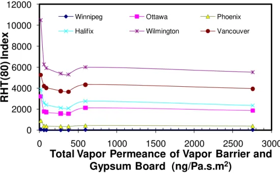
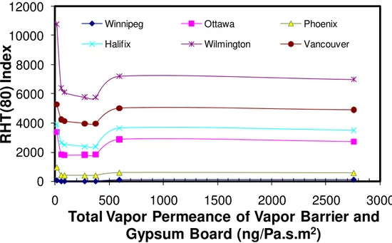
As shown in Figs. 6 to 8, the total vapor permeance of the vapor barrier and gypsum board influences the overall moisture response, in terms of RHT index, of a wood-frame stucco wall in all six locations. However, the extent of this influence varies with the location. In Winnipeg (cold and dry) and Phoenix (hot and dry) the influences seem to be relatively small. The highest variations in moisture response with the change of vapor barrier permeance are observed in Vancouver (marine) and Wilmington (warm and humid). Moreover, the moisture response variation seems to have a general pattern that is repeated in all six locations considered in this study. Without any exception, the vapor barrier with the lowest vapor permeance (15 ng/Pa.s.m2) produces the most severe moisture response (i.e. the highest value of RHT index) in all six locations. A more vapor permeable vapor barrier can reduce the intensity of the moisture response. However, it is interesting to note that the optimum moisture management (i.e. the lowest RHT index) for the wood-frame stucco wall assembly cannot be achieved either with the use of the most permeable vapor barrier nor when vapor barrier is entirely removed. The optimum moisture management is obtained when the vapor barrier permeance is between 60 and 1000 ng/Pa.s.m2 (i.e. total vapor permeance of the vapor barrier and gypsum board between 54.8 and 372.5 ng/Pa.s.m2), and interior gypsum board is coated with a primer and latex paint. In fact, the complete removal of the vapor barrier and further reduction of vapor resistance by using uncoated interior gypsum board produce much higher levels of moisture responses than the optimum case. Hence, it can be said, as shown in Figs. 6 to 8, a vapor barrier with too high or too low vapor resistance would not lead to an optimum moisture management strategy in wood-frame stucco wall assemblies, of the type represented in this study. In general, as the simulation results show, a vapor barrier that has a vapor permeance value between 60 and 1000 ng/Pa.s.m2 would produce an optimum moisture management in all six locations or climates considered in this study. However, it is also to be noted that in very cold-dry (Winnipeg), and hot-dry (Phoenix) climates a vapor barrier permeance outside of this range (60 to 1000 ng/Pa.s.m2) will have very little or no effect on the overall moisture performance of the wood-frame stucco wall.
Effect of Different Interior Climatic Conditions
The effect of different interior climatic conditions on the role of vapor barrier can be assessed from Figs. 6 to 8, and they clearly indicate that the interior conditions (RH and T) considered in this study have very little or no influence on the overall vapor diffusion strategy for optimum moisture management. In other words, vapor barrier that has a vapor permeance value between 60 and 1000 ng/Pa.s.m2 would produce optimum moisture management irrespective of the variations in interior climatic conditions considered in this study. However, in presence of a vapor barrier with higher vapor permeance or in absence of any vapor barrier, the level of moisture load in the interior climate has a greater influence on the overall moisture response of the wall.
Nevertheless it should be emphasized at this point that indoor conditions chosen in this study are aimed to represent realistic indoor temperature and relative humidity conditions. The chosen indoor conditions have not resulted in a large variation in the hygrothermal response of the wall assemblies. But, these observations do not mean that extreme indoor conditions would not have a significant impact on the moisture response of the wall assembly.
Moisture Content in Wall Components
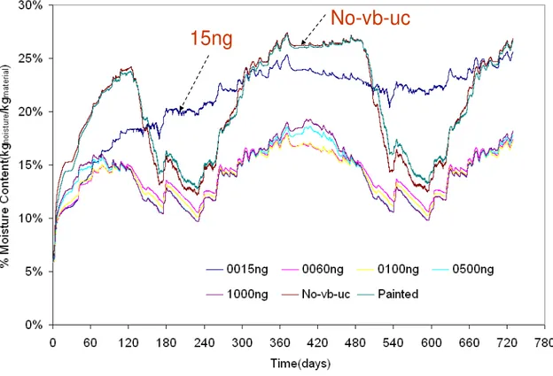
Further analyses of the moisture content in selected components of the wall assembly have been carried out in order to reaffirm or emphasize the effects of vapor permeance of the vapor barrier on the moisture management performance of the wood-frame stucco wall assemblies. Fig. 9 typically demonstrates the effect of vapor permeance of the vapor barrier on the time dependent moisture content variation in the wood-based sheathing board in Vancouver with the Weathersmart indoor condition. Furthermore, Figs. 10 to 12
summarize the ranges of moisture content variations in exterior stucco cladding, sheathing board (OSB), and interior gypsum board during the second year of simulation for all six exterior locations with the Weathersmart indoor condition. Further discussions on these plots are presented in the following sections.
Moisture Content in Exterior Stucco
The moisture content variations in exterior stucco component of the wall assembly are summarized in Fig. 10. It is very evident from this plot that moisture content variation in stucco is not greatly influenced by the vapor permeance of the vapor barrier but at the same time it appears that each location has its own moisture content variation range.
Moisture Content in Sheathing Board
The moisture content variations in the wood-based sheathing board are summarized in
Fig. 11. Very much like exterior stucco, locations with higher outdoor relative humidity and rainfall result in higher moisture content in the sheathing board. However, unlike exterior stucco, vapor permeance of the vapor barrier has a significant influence on the moisture content of the sheathing board. More importantly, it is quite interesting to observe that, very much like RHT index (moisture response indicator), moisture content in the sheathing board is minimum when vapor barrier that has a vapor permeance value between 60 and 1000 ng/Pa.s.m2.
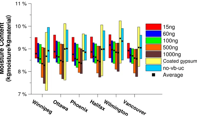
Moisture Content in Gypsum Board
The interior facing (gypsum board) also offers some vapor resistance, though not very high, to water vapor moving across the wall assembly. In the presence of a vapor barrier with lower vapor resistance (i.e. providing higher vapor permeance) or in absence of any vapor barrier in the wall assembly, the role and moisture response of the interior facing becomes more critical. In order to investigate this phenomenon the moisture contents of the interior gypsum board are summarized in Fig. 12. These results show that the moisture content of the interior gypsum board reduces significantly with the increase of the vapor permeance of the vapor barrier but at the same time removal of vapor barrier can increase the moisture content (i.e. highest, lowest and average) of the interior gypsum board.
Conclusions and Recommendations
The results and discussion presented in this paper on the role of vapor barrier in optimum moisture management can be summarized with several observations as stated below. However, it is to be noted that the observations made in this study are useful, practical and applicable only for the input conditions stated in the paper.
1. Vapor permeance characteristic of the vapor barrier plays an important role in the overall moisture management of the wood-frame stucco wall in all six North American climatic conditions considered in this study.
2. Simulation results indicate that vapor barrier permeance between 60 to 1000 ng/Pa.s.m2 (i.e. corresponding total vapor permeance of vapor barrier and gypsum board between 60 to 400 ng/Pa.s.m2) would be necessary to obtain optimum moisture management in the wood-frame stucco wall assembly in all six North American exterior climatic conditions (cold-dry, cold-humid,
cold-wet-humid, marine, and hot-dry) considered in this study. This observation differs significantly from the prevailing practices.
3. Removal of the vapor barrier does not produce optimum moisture management in wood-frame stucco wall.
4. Removal of the vapor barrier from the wall assembly can increase the moisture content (i.e. highest, lowest and average) in the sheathing board and interior gypsum board.
References
[1] National Building Code (NBC) of Canada – 2005, Part 9, National Research Council, Canada, Ottawa.
[2] Hutcheon, N. B., “Forty Years of Vapor Barriers, Water Vapor Transmission Through Building Materials and Systems: Mechanisms and Measurement. ASTM, STP 1039, 1989. [3] Swinton, M.C. and Mitalas, G.P., “The effect of separating the air and vapor barriers on moisture movement in walls - A discussion paper”, Fifth Conference on Building
Science and Technology, Toronto, Ontario, Canada, (NRCC-42507), 1990, pp. 133-155.
[4] Straube, J.F., “The Influence of Low-Permeance Vapor Barriers on Roof and Wall Performance”, Thermal Performance of the Exterior Envelopes of Buildings VIII,
Proceedings of ASHRAE THERM VIII, Clearwater, FL, 2001, pp. 1-12.
[5] Karagiozis, A. N., Lstiburek, J., and Desjarlais, A., “Scientific Analysis of Vapor Retarder Recommendations for Wall Systems Constructed in North America”, Thermal
Performance of the Exterior Envelopes of Buildings X, Proceedings of ASHRAE THERM X, Clearwater, FL, 2007, pp. 1-11.
[6] Karagiozis, A. N. and Kumaran, M. K., “Computer Model Calculations – The Performance of Vapor Barriers in Canadian Residential Buildings”, ASHRAE
Transactions, Vol. 99, Part 2, 1993.
[7] National Building Code (NBC) of Canada – 1990, Part 9, National Research Council, Canada, Ottawa.
[8] Mukhopadhyaya, P., Kumaran, M.K., van Reenen, D. and Tariku, F., “Influence of Sheathing Membrane and Vapor Barrier on Hygrothermal Response of Stucco Walls”,
International Conference on Building Science and Technology (ICBEST), Ottawa,
Canada, 2001, pp. 6.
[9] Mukhopadhyaya, P., Kumaran, and van Reenen, D., "Role of Vapor Barrier and Interior Weather on Overall Moisture Performance of Exterior Wall Assembly – Results from Hygrothermal Simulations", CIB World Building Congress 2004, Toronto, Canada, 2004, pp. 1-10, http://irc.nrc-cnrc.gc.ca/pubs/fulltext/nrcc46864/nrcc46864.pdf.
[10] Hens, H., “Heat, Air and Moisture Transport”, Final Report, Vol. 1, Task 1: Modeling, International Energy Agency Annex 24, Laboratorium Bouwfysica, K. U.-Leuven, Belgium, 1996.
[11] Maref, W., Kumaran, M. K., Lacasse, M. A. Swinton, M. C. and van Reenen, D., “Advanced hygrothermal Model- hygIRC: Laboratory Measurements and Benchmarking”, 12th International Heat Transfer Conference, Grenoble, 2002, pp. 1-6. [12] Maref, W., Lacasse, M.A., and Booth, D.G., "Large-scale laboratory measurements and benchmarking of an advanced hygrothermal model", CIB 2004 Conference (Toronto, Ontario, May 2004, pp. 1-11,
[13] Karagiozis, A., “Analysis of the Hygrothermal Behavior of Residential High-Rise Building Components”, Client Report A-3052.4, IRC/NRC, National Research Council, Canada, Ottawa, 1997.
[14] Djebbar, R., Kumaran, M.K., Van Reenen, D. and Tariku, F., “Hygrothermal Modeling of Building Envelope Retrofit Measures in Multi-unit Residential and Commercial Office Buildings”, IRC/NRC, National Research Council, Ottawa, Canada, Client Final Report B-1110.3, 2002, pp. 187.
[15] Mukhopadhyaya, P. and Kumaran, M. K., “Prediction of Moisture Response of Wood Frame Walls Using IRC’s Advanced Hygrothermal Model (hygIRC)”, 2nd Annual
Conference on Durability and Disaster Mitigation in Wood-Frame Housing, 2001, pp.
221-226.
[16] Mukhopadhyaya, P., Kumaran, M.K., Tariku, F., and Van Reenen, D., “Application of Hygrothermal Modeling Tool to Assess Moisture Response of Exterior Walls," Journal
of Architectural Engineering, 12, (4), 2006, pp. 178-186, doi:10.1061/(ASCE)1076-0431(2006)12:4(178).
[17] Mukhopadhyaya, P., Goudreau, P., Kumaran, M. K. and van Reenen, D., “Influence of Material Properties on the Hygrothermal Response of an Ideal Stucco Wall - Results from Hygrothermal Simulations”, 6th Nordic Building Physics Symposium 2002, Trondheim, Norway, 2002, pp. 611-618.
[18] Kumaran, K., Lackey, J., Normandin, N., van Reenen, D. and Tariku, F., “Summary Report from Task 3 of MEWS Project”, Institute for Research in Construction, National
Research Council, Ottawa, Canada, (NRCC-45369), 2002, pp. 1-68.
[19] Kumaran, K., Lackey, J., Normandin, N., Tariku, F and van Reenen, D., “A Thermal and Moisture Transport Property Database for Common Building and Insulating Materials”, Final Report from ASHRAE Research Project 1018-RP, 2004, pp. 1-229. [20] Cornick, S. M., Dalgliesh, W. A., Said, N. M., Djebbar, R., Tariku, F. and Kumaran, M. K. “Task 4- Environmental conditions’. Institute for Research in Construction,
National Research Council, Ottawa, Canada, (NRCC-45222), 2002, pp. 1-106.
[21] American Heating, Refrigerating and Air-Conditioning Engineers, Inc. “Commercial and Public Buildings.” ASHRAE Applications Handbook, Chap. 3, Atlanta, 1999.
[22] Swinton, M.C. and Sander, D.M., “Trade-off Compliance for Houses: Specifications for Calculation Procedures for Demonstrating Compliance to the National Energy Code for Houses”, National Research Council, Canada, NRCC-39861, 1994, pp. 46.
[23] Djebbar, R., van Reenen, D. and Kumaran, M. K., “Environmental Boundary Conditions for Long-term Hygrothermal Calculations”, 8th International Conference on
Building Envelopes, Clearwater Beach, Florida, USA, 2001, p. 13.
[24] Jones, R., “Indoor Humidity Calculation Procedures”, Building Services Engineering
Research & Technology, Volume 16, No. 3, 1995, pp 119-126.
[25] Nofal, M. and Morris, P.I., “Criteria for Unacceptable Damage on Wood Systems”,
Japan-Canada Conference on Building Envelope, Vancouver, Canada, 2003, pp. 1-14.
[26] Kumaran M. K., Mukhopadhyaya P., Cornick S. M., Lacasse, M. A., Maref W., Rousseau M., Nofal M., Quirt J. D. & Dalgliesh W. A., “An Integrated Methodology to Develop Moisture Management Strategies for Exterior Wall Systems”, 9th Conference on
Building Science and Technology, Vancouver, Canada, 2003, pp. 16.
[27] Mukhopadhyaya, P., “MEWS Project Produces Long-term Moisture Response Indicator” Construction Innovation, Volume 8, No. 1, 2003, pp. 6-7.
[28] Mukhopadhyaya, P., Kumaran, M. K., Rousseau, M., Tariku, F., van Reenen, D. and Dalgliesh, A., “Application of Hygrothermal Analyses to Optimize Exterior Wall Design”, 2nd International Conference on Research in Building Physics, Leuven, Belgium, 2003, pp. 417-426.
[29] Mukhopadhyaya, P., van Reenen, D., Kumaran, M.K., Copeland, C., Newman, P.J., El Khanagry, R., and Zalok, E., “Moisture Performance Assessment of Wood-Frame Exterior Building Envelope Construction in China”, 8th Nordic Symposium on Building
Physics, Copenhagen, 2008, pp. 1-8.
TABLE 1 - Parametric variations considered
Exterior Locations Indoor Conditions
Vapor Barrier Combinations Permeance of Vapor Barrier (ng/Pa.s.m2) Gypsum Board Total Permeance of Barrier and Gypsum
(ng/Pa.s.m2)
Winnipeg Constant 15 Coated 14.7
Ottawa ASHRAE 60 Coated 54.8
Phoenix Weathersmart 100 Coated 86.0
Halifax 500 Coated 271.9
Wilmington 1000 Coated 372.5
Vancouver No barrier (no-vb) Coated 591.3
FIG. 1 - Basic wall construction details
FIG. 2 - Climates considered in this study Gypsum [12mm] Vapour Barrier [0.152mm] Insul. Space [89 mm] Sheathing Board [11mm] Sheath. Memb. [0.23mm] Stucco Cladding [19 mm] 00 24 Bott. Plate ht. [76 mm] Area [650x1.5 mm2] of the sheathing board selected for RHT index calculation
Indoor Condition - ASHRAE 0 10 20 30 40 50 60 70 80 0 2000 4000 6000 8000 10000 Time (hours) R e la ti v e H u m id ity (% 20 25 30 35 40 Relative Humidity (%) )
FIG. 3a - Indoor climate (ASHRAE, Vancouver)
Temperature (deg C)
Indoor Condition - Weathersmart
0 10 20 30 40 50 60 70 80 0 2000 4000 6000 8000 10000 Time (hours) R e la ti v e H u m id ity ( % 20 25 30 35 40 ) Relative Humidity (%) Temperature (deg C)
Wall Width (m) - Expanded Wa ll He ig h t (m ) 0.05 0.1 0.5 1 1.5 2 RH 0.9346 0.8723 0.8100 0.7477 0.6854 0.6231 0.5608 0.4985 0.4362 0.3739 0.3115 0.2492 0.1869 0.1246 0.0623
Wall Width (m) - Expanded
W a ll H e ight (m ) 0.05 0.1 0.5 1 1.5 2 T 18.8822 17.6151 16.3480 15.0808 13.8137 12.5465 11.2794 10.0123 8.7451 7.4780 6.2109 4.9437 3.6766 2.4094 1.1423 St u c c o S th e athin g bo a rd Region of focus Temperature Contour Relative Humidity Contour
FIG. 4 - Typical outputs from hygIRC-2D
0 2000 4000 6000 8000 10000 12000 0 500 1000 1500 2000 2500 3000
RHT
(8
0
) I
n
d
e
x
Total Vapor Permeance of Vapor Barrier and
Gypsum Board (ng/Pa.s.m
2)
ASHRAE
Winnipeg Ottawa Phoenix
Halifix Wilmington Vancouver
(a) RHT(80) variation 0 200 400 600 800 1000 1200 0 500 1000 1500 2000 2500 3000
RHT
(9
5
) I
n
d
e
x
Total Vapor Permeance of Vapor Barrier and
Gypsum Board (ng/Pa.s.m
2)
ASHRAE
Winnipeg Ottawa Phoenix
Halifax Wilminton Vancouver
(b) RHT(95) variation
FIG. 6 - RHT Index variations due to different permeance of vapor barrier (ASHRAE
0 2000 4000 6000 8000 10000 12000 0 500 1000 1500 2000 2500 3000
RHT
(8
0
) I
n
d
e
x
Total Vapor Permeance of Vapor Barrier and
Gypsum Board (ng/Pa.s.m
2)
Constant
Winnipeg Ottawa Phoenix
Halifix Wilmington Vancouver
(a) RHT(80) variation 0 200 400 600 800 1000 1200 0 500 1000 1500 2000 2500 3000
RHT
(9
5
) I
n
d
e
x
Total Vapor Permeance of Vapor Barrier and
Gypsum Board (ng/Pa.s.m
2)
Constant
Winnipeg Ottawa Phoenix
Halifax Wilminton Vancouver
(b) RHT(95) variation
FIG. 7 - RHT Index variation due to different permeance of vapor barrier (Constant
0 2000 4000 6000 8000 10000 12000 0 500 1000 1500 2000 2500 3000
RHT
(8
0
) I
n
d
e
x
Total Vapor Permeance of Vapor Barrier and
Gypsum Board (ng/Pa.s.m
2)
Weathersmart
Winnipeg Ottawa Phoenix
Halifix Wilmington Vancouver
(a) RHT(80) variation 0 200 400 600 800 1000 1200 0 500 1000 1500 2000 2500 3000
RHT
(9
5) I
n
d
e
x
Total Vapor Permeance of Vapor Barrier and
Gypsum Board (ng/Pa.s.m
2)
Weathersmart
Winnipeg Ottawa Phoenix
Halifax Wilminton Vancouver
(b) RHT(95) variation
FIG. 8 - RHT Index variation due to different permeance of vapor barrier (Weathersmart
15ng
No-vb-uc
FIG. 9 - Moisture content in sheathing board (Weathersmart, Vancouver,)
0 % 4 % 8 % 12 % 16 %
Mo
isture Con
tent
(kg
mo
istur
e
/k
g
mate
rial
)
FIG. 10 - Range of moisture content in the stucco cladding (Weathersmart) 15ng 60ng 100ng 500ng 1000ng painted no-vb-uc Win
nipegOttawa Phoenix HalifaxWilming ton Van cou ver Average Coated gypsum 30 % 20 %
tent
terial ) 15ng 60ng 100ng aFIG. 11 - Range of moisture content in sheathing board (Weathersmart) 7 % 8 % 9 % 10 % 11 %
Moistu
FIG. 12 - Range of moisture content in interior gypsum board (Weathersmart)
Win
nipegOttawa Phoenix alifaxWilming ton Van cou ver H