Colloidal Magnetic Fluids as Extractants for Chemical
Processing Applications
by
Geoffrey D. Moeser
B.Sc. Eng. Chem., Queen's University, Kingston, ON, Canada (1998)
M.S.C.E.P. Chem. Eng., Massachusetts Institute of Technology, Cambridge, MA (2000) Submitted to the Department of Chemical Engineering in partialfulfillment of the
requirements Jbr the degree of
Doctor of Philosophy at the
Massachusetts Institute of Technology September 2003
MASSACHUSETTS INSTiTUTE
OF TECHNOLOGY
OCT 2 2 2003
LIBRARIES
© 2003 Massachusetts Institute of Technology. All rights reserved.
Signature of Author ...
Department of Chemical Engineering August 22, 2003
Certified
by ...
...
. ... ...
T. Alan Hatton Ralph Landau Professor of Chemical Engineering Practice Thesis Supervisor Certified by . ...7'
William H. Green, Jr. Texaco-Mangelsf Assistant Professor of Chemical Engineering Thesis Supervisor
Certified
by. ...
-r...
..
...
P...
Lb
by/f~~~~~~~~~~~
Paul
E.
Laibinis
Associate Professor of Chemical Engineering, Rice University Thesis Supervisor
Accepted
by...
...
... ...
Daniel Blankschtein Professor of Chemical Engineering Chairman, Committee for Graduate Students
Colloidal Magnetic Fluids as Extractants for Chemical
Processing Applications
by
Geoffrey D. Moeser
Submitted to the Department of Chemical Engineering on August 22, 2003, in partial fulfillment of the requirements for the degree of
Doctor of Philosophy in Chemical Engineering
Abstract
This focus of this thesis is a novel class of water-based magnetic fluids that are specifically tailored to extract soluble organic compounds from water. Magnetic fluids are colloidal dispersions of magnetic nanoparticles that do not settle in gravitational or moderate magnetic fields due to their small size and do not aggregate because of their surface coatings. These materials offer several potential advantages over traditional methods of organic separation, such as activated carbon adsorption. For example, magnetic fluids possess a large surface area for separation while avoiding porous structures that- introduce a high mass transfer resistance.
The magnetic fluids were prepared by precipitation and consist of a suspension of
-7.5 nm diameter magnetite (Fe304) nanoparticles coated with a -9 nm thick bifunctional
polymer layer comprised of an outer hydrophilic polyethylene oxide (PEO) region for colloidal stability, and an inner hydrophobic polypropylene oxide (PPO) region for solubilization of organic compounds. Characterization of these materials revealed the particle dimensions and magnetic properties. In addition, we examined the colloidal stability of the magnetic fluids over a broad range of conditions. The structure of the polymer shell, which was examined with neutron scattering and lattice calculations, shows some evidence of segregation of the PEO and PPO chains. The magnetic fluids exhibit a high capacity for organic solutes, with partition coefficients between the polymer coating and water on the order of 103 to 105, which is consistent with values reported for solubilization of these organics in PEO-PPO-PEO block copolymer (Pluronic) micelles.
The feasibility of using high gradient magnetic separation (HGMS) to separate the Fe304 nanoparticles was studied in this work. We present a general model for
nanoparticle capture based on calculating the limit of static nanoparticle buildup around the collection wires in an HGMS column. Model predictions were compared successfully with experimental results from a bench-scale HGMS column. Permanent capture of individual nanoparticles is limited by diffusion away from the wires; however, 60-125 nmrr aggregates of particles can be captured permanently in the bench-scale column. The model provided estimates of the minimum particle size for permanent capture of individual nanoparticles and nanoparticle aggregates.
Thesis Supervisor: T. Alan Hatton
Title: Ralph Landau Professor of Chemical Engineering Practice Thesis Supervisor: William H. Green, Jr.
Title: Texaco-Mangelsdorf Assistant Professor of Chemical Engineering Thesis Supervisor: Paul E. Laibinis
Acknowledgements
I would first like to sincerely thank my advisors Alan Hatton, Paul Laibinis, and Bill Green for all of their guidance during my time at MIT. Without their ideas, advice, suggestions, and support, this project would never have been completed. I also want to thank them for the independence that I was allowed, as I believe it made me a much better researcher. The final direction of this project was not what we anticipated when we began, but I hope and think that this work will stand as a useful contribution to those who follow. I would also like to thank my thesis committee members, Professors Tester and Hammond, for all of their contributions during my committee meetings. Your opinions came from a different viewpoint and were extremely useful in shaping the direction of the project.
I also need to thank all of the people who helped me in conducting the experimental work in this thesis. Without a doubt, the most important of these was Kaitlin Roach, who during her three years in the UROP program became an excellent researcher and certainly contiibuted more to this work than anyone. Her enthusiasm and tireless effort will be greatly missed. In addition, I would like to thank those researchers who assisted me, including Mike Frongillo and Fangcheng Chou of the MIT CMSE, Steve Kline and John Barker of NIST, MD, Paul Johnson of the University of Rhode Island, Monique Dubois of CEA, France, and Per Linse of the University of Lund. It goes without saying that I need to thank Hatton group members past and present for their help. In particular, I need to thank Lifen Shen and Seif-Eddeen Fateen for sharing their knowledge of magnetic fluids with me in the early stages, Tim Finegan for keeping the computers and lab running smoothly, and Sonja Sharpe for being an understanding cubicle neighbor. In addition, this department would not and will not function without people like Carol Phillips, Arline Benford, Beth Tuths, and Susan Lanza. I must also say thanks to all of my friends in the department with whom I shared everything from party planning to White Mountain hikes.
Without my family I wouldn't be here (literally!), so I would like to thank my parents Cathy and Doug Moeser for their unrelenting emotional and financial support for so many years. I'd also like to thank my brother Andrew Moeser for his inspiring way of living life, even if we don't see each other enough. Thanks also to Ethel-Rose and Edward Steinberger for always treating me like a party of your family, even if I technically wasn't for a very long time.
A final thank you goes to my fiancee Stacie Steinberger, for !'e incredible support throughout the last ten years, but particularly for the last five years, when we lived together, but when it sometimes seemed like all we shared was the same mailing address and a very needy cat. Without your support, I would never have been able to make it to this point.
Table of Contents
Chapter 1: Introduction
17
1.1 Motivation and Approach ... 17
1.2 Background: Magnetic Fluids ... 20
1.2.1 Structure ... 20
1.2.2 Magnetic Fluid Synthesis ... ... 23
1.2.2.1 General Concepts ... ... 23
1.2.2.2 Size Reduction ... 23
1.2.2.3 Organometallic Decomposition ... 23
1.2.2.4 Chemical Coprecipitation ... 24
1.2.3 Applications of Magnetic Fluids ... ... 25
1.2.3.1 Industrial Applications ... .. 25
1.2.3.2 Biomedical Applications ... ... 25
1.2.3.3 Biological Separations ... ... 26
1.2.3.4 Environmental Separations ... 27
1.2.3.5 Magnetophoretic Separations with Magnetic Fluids ... 27
1.3 Background: Magnetic Separations ... ... 28
1.3.1 Types of Magnetic Separation ... ... 28
1.3.2 High Gradient Magnetic Separation ... 28
1.3.3 Magnetic Fluids and HGMS ... 29
1.4 Research Overview ... 30
1.5 Bibliography ... 31
Chapter 2: Magnetic Fluid Synthesis and Characterization
37
2.1 Introduction ... 37 2.2 Experim ental ... 38 2.2.1 M aterials ... 38 2.2.2 Polymer Synthesis ... 39 2.2.3 Nanoparticle Synthesis ... 40 2.2.4 Instrumentation ... 41 2.3 Characterization Results ... 42 2.3.1 Polymer Characterization ... ... 422.3.2 Particle Formation and Polymer Attachment ... 43
2.3.3 Electron Microscopy ... ... 47
2.3.4 Magnetic Properties ... 49
2.3.5 Dynamic Light Scattering: Hydrodynamic Size ... 52
2.4 Colloidal Stability ... 55
2.5 Control of Core Size and Magnetization ... 58
2.6 Summary ... 60
2.7 Bibliography ... 61
Chapter 3: Structural Analysis of Polymer Shell
63
3.1 Introduction ... 633.2 Experimental ... 64
3.2.1 Materials... 64
3.2.2 Preparation of Magnetic Fluids ... 65
3.2.3 Electron Microscopy Measurements ... 66
3.2.4 SANS Measurements ... 66
3.3 Scattering Theory ... 66
3.3.1 General Scattering Equations ... ... 66
3.3.2 Form Factor Models ... 68
3.3.3 Structure Factor Model ... 72
3.3.4 SANS Fitting Approach ... 73
3.4 SANS Results ... 74
3.4.1 Determ ination of Core Parameters ... 74
3.4.2 Global Fit of Shell Parameters ... 77
3.5 Self-Consistent Lattice Calculations ... 86
3.5.1 Overview of Theory ... ... 86
3.5.2 Parameters for Calculations ... 89
3.5.3 Results of Lattice Calculations ... . 91
3.5.4 Comparison with SANS Results ... 94
3.6 Summary ... 97
3.7 Bibliography ... 98
Chapter 4: Organic Solubilization
101
4.1 Introduction ... 1014.2 Experimental ... ... 102
4.2.1 Materials ... 102
4.2.2 Preparation of Magnetic Fluids ... 102
4.2.3 Solubility Measurements at Saturation ... 103
4.2.4 Fluorescence Experiments ... ... 104
4.3 Solubilization Results ... 104
4.3.1 Saturation Experiments ... 104
4.3.2 Linear Free Energy Relationship ... ... 107
4.3.3 Fluorescence Measurements of Solubility ... 1 1 4.4 Summary ... 114
4.5 Bibliography ... ... 115
Chapter 5: Magnetic Separation of Nanoparticles
117
5.1 Introduction ... 1175.2 Experimental ... 118
5.2.1 Materials ... 118
5.2.2 Preparation of Magnetic Fluids ... ... 119
5.2.3 High Gradient Magnetic Separation ... 120
5.2.4 Particle Characterization ... 121
5.3 HGMS Modeling ... 121
5.3.1 Overview of Model and System ... ... 121
5.3.2 Derivation of Forces ... 123
5.3.2.1 Drag Force ... 123
5.3.2.2 Diffusive Force ... ... 124
5.3.2.3 Magnetic Force ... 125
5.3.3 Derivation of Limit of Nanoparticle Buildup ... 126
5.3.3.1 Force Balance ... 126
5.3.3.2 Definition of Limiting Conditions ... 127
5.3.3.3 Diffusion Buildup Limit ... ... 128
5.3.3.4 Drag Force Buildup Limit ... 129
5.3.3.5 Dimensionless Force Ratios ... 129
5.4 Magnetic Filtration Experiments ... 130
5.4.2 Buildup Profile Calculations ... 136
5.4.3 Magnetic Chromatography Results ... 143
5.4.4 Comparison of Buildup with Void Space ... 145
5.4.5 Comments on Capture of Individual 1Nanoparticles ... 147
5.5 Comparison with Phospholipid-Coated Particles ... 147
5.6 Aggregate Formation: A Preliminary Study .. ... 152
5.7 Summary ... 156
5.8 Bibliography ... 158
Chapter 6: Conclusions 161 6.1 Summary of Research ... 161
6.2 Process Considerations ... 163
6.3 Future Research Directions ... 166
List of Figures
Figure 1-1. A process using functionalized magnetic nanoparticles as separation
agents to remove organic compounds from water... 18
Figure 1-2. General structure of a magnetic fluid ... 20
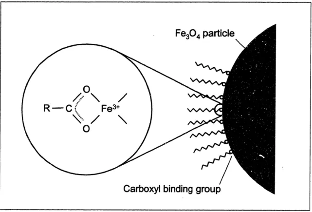
Figure 1-3. Attachment of carboxyl groups to the surface of a magnetite particle ... 22
Figure 2-1. Aqueous magnetic fluid synthesis... 38
Figure 2-2. Amphiphilic graft copolymer synthesis ... 39
Figure 2-3. (a) IR spectrum of the 16/0 graft copolymer. (b) Comparison of the IR spectra of a series of graft copolymers with PEO side chains grafted to 8, 16, and 24% of the carboxylic acid groups in the backbone ... 44
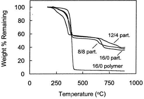
Figure 2-4. TGA analysis of graft copolymer and magnetic fluids ... 45
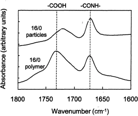
Figure 2-5. IR comparison of carbonyl groups before and after attachment of 16/0 graft copolym er to m agnetite... 47
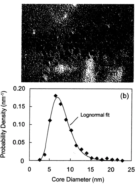
Figure 2-6. (a) TEM image and (b) particle size distribution of 16/0 particles as fit ' byfa lognormal particle size distribution... 48
Figure 2-7. High resolution TEM image of 16/0 particles... 49
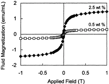
Figure 2-8. Magnetization response of 16/0 particles from SQUID measurements .... 50
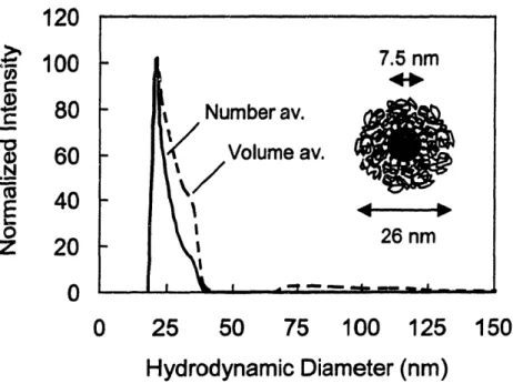
Figure 2-9. Size distribution of 16/0 particles from dynamic light scattering ... 53
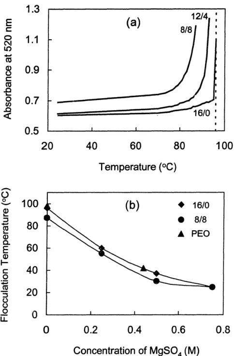
Figure 2-10. (a) Turbidity of dilute magnetic fluids indicates the critical flocculation temperature of the particles. (b) Flocculation temperature (temperature at which the turbidity increases dramatically) as a function of ionic strength in M gSO 4solutions... 56
Figure 2-11. Zeta potential of dilute magnetic fluids ... 58
Figure 3-1. Solvent penetration models for the magnetic nanoparticle form factor (a) Constant solvent volume fraction in the polymer shell. (b) Linear solvent volume fraction profile... 70
Figure 3-2. Neutron scattering data for magnetic fluids in 75% H20 / 25% D20... 75
Figure 3-3. Neutron scattering data for the 8/8 magnetic fluid in 82% H20 / 18% D 20. ... 76
Figure 3-4. Global fit of neutron scattering from the magnetic fluids with the constant solvent model (Figure 1 a). Data are shown for the (a) 16/0, (b) 12/4, and (c) 8/8 magnetic fluids in five aqueous solvents with a varying level of deuteration .... 80
Figure 3-5. Comparison of predicted structure factor for the magnetic fluids ... 83
Figure 3-6. Global fit of neutron scattering from the magnetic fluids with the linear solvent penetration model (Figure lb). Data are shown for the (a) 16/0, (b) 12/4, and (c) 8/8 magnetic fluids in five aqueous solvents with a varying level of deuteration.... 84
Figure 3-7. Results of lattice calculations for (a) 16/0, (b) 12/4, and (c) 8/8
m agnetic fluids... 92
Figure 3-8. Structural comparison of Pluronic micelles with coated magnetite
nanoparticles . ... 94
Figure 3-9. Comparison of water volume fraction profile in polymer shell from (a)
lattice calculations, (b) neutron scattering data assuming a linear solvent profile, and (c) neutron scattering data assuming a constant solvent volume fraction in the shell... 96
Figure 4-1. Toluene solubility in various aqueous magnetic fluids. (a) The toluene
solubility increases with particle concentration for magnetic fluids that contain PPO side chains. (b) The solubility in the polymer shell is linear with the weight fraction of PPO in the polymer, suggesting that PPO is responsible for organic solubilization. 105
Figure 4-2. Linear free energy relationship of PPO-water partition coefficients ... 110 Figure 4-3. Fluorescence of pyrene (5.0 x 10⁻⁷ M) in various aqueous magnetic
fluids (0.005 wt% Fe304). (a) The fluorescence emission decreases as the polymer shell contains more PPO side chains. (b) The decrease in fluorescence is directly
proportional to the PPO content of the polymer shell ... 112
Figure 4-4. Linear free energy relationship of PPO-water partition coefficients for
PA H solutes... 114
Figure 5-1. The HGMS model system. is based on an isolated magnetically
susceptible wire magnetized perpendicular to its axis, in a flow field oriented
perpendicular to both the wire axis and the magnetic field ... 122
Figure 5-2. Batch filtration results from a repetitive cycle of magnetic washing ... 132 Figure 5-3. Effect of size on particle capture during magnetic washing. (a) The
Fe304core size distribution (from TEM) of particles in the first 16/0 filtrate is
compared to the initial distribution. (b) The hydrodynamic diameter (from DLS) of particles in the first and third 16/0 filtrate is compared to the initial distribution ... 133
Figure 5-4. (a) Effect of fluid velocity on batch HGMS capture of 16/0 magnetic
fluid. (b) Effect of flow velocity on the dimensionless numbers expressing the ratio of the magnetic force to the diffusive force (K,,d) and fluid drag force (K,,,,) ... 135
Figure 5-5. Predicted diffusion (black line) and fluid drag force (gray line) limits of
static buildup for polymer-coated nanoparticles. (a) Predictions when the magnetic field and fluid flow are perpendicular, as is the case for our apparatus and
experiments. (b) Predictions when the magnetic field and fluid flow are parallel (and opposite)... 137
Figure 5-6. Comparison of model predictions with different velocity profile
solutions ... 139
Figure 5-7. Effect of the nanoparticle core size on the static buildup volume. (a)
The calculated volume of the static buildup limit (normalized by the wire volume) is plotted against the flow velocity (V). (b) The static buildup limit for different core
Figure 5-8. Effect of flow velocity on the static buildup volume of aggregates ... 142
Figure 5-9. Magnetic chromatography of 16/0 magnetic fluid ... 144
Figure 5-10. The static buildup volume of individual polymer-coated nanoparticles
and particle aggregates compared to the void volume of the column ... 146
Figure 5-11. (a) Magnetic chromatography of the phospholipid-coated magnetic
nanoparticles. (b) The calculated fraction of particles lost from the column ... 149
Figure 5-12. Predicted diffusion (black line) and drag force (gray line) limits of
static buildup for the phospholipid-coated nanoparticle aggregates ... 150
Figure 5-13. The static buildup volume of the phospholipid-coated particle
aggregates compared to the void volume of the column ... 151
Figure 5-14. Weight-average hydrodynamic diameter of aggregated 16/0 magnetic
fluids... 153
Figure 5-15. Magnetic chromatography of aggregated 16/0 magnetic fluids ... 154
Figure 6-1. Integration of magnetic nanoparticles in a process to extract organic
List of Tables
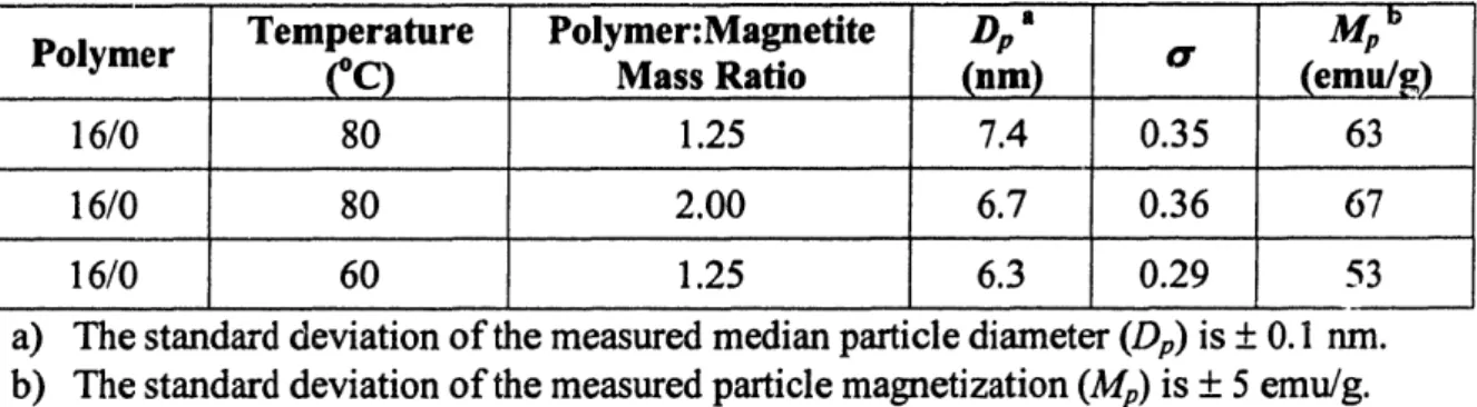
Effect of synthetic conditions on core size and magnetization ... Scattering length densities for materials in the magnetic fluids... Results of global fit assuming a constant solvent volume fraction in shell Results of global fit assuming a linear solvent volume fraction in shell... Parameters used in lattice calculations... Organic solubility in 8/8 magnetic fluids and in water ... HGMS results for aggregated 16/0 magnetic fluids...
Table 2-1. Table 3-1. Table 3-2. Table 3-3. Table 3-4. Table 4-1. Table 5-1. 60 69 81 85 90 107 156
Chapter 1
Introduction
1.1 Motivation and Approach
Synthetic organic compounds are common contaminants in both plant wastewater and drinking water, and must be removed before the water can be discharged or consumed. These contaminants include volatile organic compounds such as toluene and dichlorobenzene, as well as non-volatile compounds like polyaromatic hydrocarbons (PAH) and polychlorinated biphenyls (PCB). Organic compounds can enter drinking water supplies through leaking underground tanks, agricultural and urban runoff, or improperly disposed waste.1 In water, these species are often soluble in low concentration, making standard coagulation and sedimentation techniques ineffective. In addition, their extremely low concentration (1 ppb to 1 ppm)' makes traditional separation methods like distillation and solvent extraction infeasible.
The most commonly used techniques for the removal of synthetic organics from water are activated carbon adsorption and air stripping. While these techniques have been widely implemented, they have several drawbacks associated with them. One important limitation of activated carbon adsorption is the highly porous structure of the carbon beads, which leads to long contacting times because of the high mass transfer resistance.2 Additional disadvantages include a high pressure drop across the bed, the possibility of bacterial growth in the carbon, the potential for clogging due to suspended solids, and the difficulty of regenerating activated carbon without degrading the porous structure.2' 3 Air stripping, which is only suitable for volatile organics, also suffers from clogging due to suspended solids and produces a contaminated ai: stream that must be either discharged or further treated.3 Newer techniques for organic removal from water include oxidation with ozone4 or UV radiation,5 anaerobic microbial decomposition,6
reverse osmosis,7 and micellar separation.8 9 These techniques have the potential to
overcome many of the negative aspects of activated carbon adsorption. However, they present additional processing problems. Ozonolysis, for example, has high operating
costs associated with ozone production and in some cases the ozonolysis products are more toxic than the original organics.4 Reverse osmosis processes are complicated by
membrane fouling,7 while micellar separation requires a complicated ultrafiltration process 9or precise control of temperature and pH to form a dense surfactant phase.8 As an alttinative strategy, we have developed water-based magnetic fluids for organic extraction that could offer several advantages over traditional separation techniques.
Figure 1-1. A process using functionalized magnetic nanoparticles as separation agents
to remove organic compounds from water. After contacting the particles with a contaminated water stream, the organic-loaded particles are removed with high gradient magnetic separation. Following regeneration of the particles by removing the organics, the nanoparticles can be recycled to the contacting stage. Note that this figure is conceptual and features are not necessarily to scale.
Magnetic fluids, which are reviewed in detail in the next section, are stable colloidal dispersions of magnetic nanoparticles -10 nm in diameter. Our magnetic fluids are water-based and consist of magnetite (Fe304) nanoparticles coated with a polymer
that is specifically tailored to separate soluble organic compounds from water. This polymer coating consists of an outer hydrophilic region that provides colloidal stability in
-10 nm nano susp Regen magi nanop suspe er
water and an inner hydrophobic region that provides an extraction medium for organic compounds. Figure 1-1 illustrates conceptually how these magnetic fluids could be used in a separation process for dilute synthetic organic compounds. In the contacting stage, a concentrated suspension of the magnetic nanoparticles is added to a contaminated water stream, where the particles disperse and absorb organics in the hydrophobic part of their polymer coating. After the particles are loaded with the target organics, the suspension is passed through a high gradient magnetic separation (HGMS) column that traps the particles but allows purified water to flow through. When the HGMS column is saturated with particles, the magnetic field is removed and the particles are regenerated or disposed of.
Magnetic fluids offer several potential advantages for organic separation, many of which arise from the nanometer size of the particles. These materials provide very high surface area, even when the nanoparticles are dispersed at low volume fractions. For example, a 0.1 vol% suspension of 10 nm particles has an accessible surface area/solution volume ratio of 6 x 10⁵m2/m3, whereas 10 !gm particles at the same volume fraction have an area of only 6 x 10² m2/m3. The high surface area of these nanoparticles is obtained without the incorporation of a porous structure like in activated carbon beads that also introduces a high mass transfer resistance. The result is that the kinetics of organic absorption will be rapid for the nanoparticles. For an organic diffusivity of 5 x 10⁻¹⁰ m2/s, a 0.1 vol% suspension of 10 nm particles has a characteristic diffusion time
(-R2/D/ 32 , where R is the particle radius, D is the solute diffusivity, and 0 is the particle volume fraction) of 5 s, while 10 ptm particles at the same concentration have a characteristic diffusion time of 5 s. Thus, the transport-limiting process is the rate of dispersion of these nanoparticles in the separation mixture. Our proposed process in Figure 1-1 offers several additional advantages over traditional processes for organic removal. The relatively open structure of an HGMS column could allow suspended solids to be passed without clogging, whereas activated carbon requires that streams be clarified before processing.3 An HGMS system can also be cycled rapidly on and off to regenerate the filter, while activated carbon requires a time-consuming thermal treatment that can degrade the porous structure.2 As a result of the low mass transfer resistance of
the particles and ease of regeneration of the HGMS column, magnetic fluids could allow more rapid processing of contaminated streams than conventional fixed bed systems like activated carbon adsorption.
1.2 Background: Magnetic Fluids
1.2.1 Structure
Magnetic fluids, also known as ferrofluids, are colloidal dispersions of magnetic nanoparticles that do not settle in gravitational or moderate magnetic fields due to their small size and do not aggregate because of their surface coatings. The structure of a magnetic fluid is shown schematically in Figure 1-2. The nanoparticles can be either ferromagnetic materials such as iron or cobalt, or ferrimagnetic materials, the most common of which is magnetite (Fe304).° This compound is a spinel iron oxide species with a 2:1 molar ratio of Fe ions in their III and II oxidation states."] Magnetite is not
Dispersion medium
Stabilizing layer
A " UI ', _ -rMagnetic
. .,a - 'L S i =nanoparticie ,
~10
nm
Inf
I--%.Figure 1-2. General structure of a magnetic fluid. Magnetic fluids consist of magnetic nanoparticles dispersed in a liquid medium, with a stabilizing layer around the particles to prevent flocculation. Each particle has a magnetic dipole but the suspension as a whole has zero net magnetization due to dipole fluctuations.
--LI -'~%
1 I/
I J-l ' /11IN-, .r -C,,prone to oxidation, which is an advantage over magnetic fluids based on cobalt or iron nanoparticles, which tend to lose their magnetic propert;is over time.12 The typical particle size is -10 nm, which is sufficiently small to revent sedimentation of the particles, as Brownian motion will dominate the gravitational force and the magnetic force from a typical handheld magnet for a particle of this size.l °
Without a stabilizing layer, the 10 nm particles in a magnetic fluid would rapidly flocculate due to the van der Waals attractive force that exists between particles in a dispersion medium and then settle. The van der Waals force is more important than interparticle magnetic attraction at short range for a moderately magnetic material like magnetite.13 The role of the stabilizing layer is to prevent flocculation by exerting a repulsive force between particles at short range. The nature of the stabilizing layer depends on the dispersion medium. If the dispersion medium is a hydrocarbon, steric stabilization from an attached surfactant or polymer is typically used.'4 In an aqueous magnetic fluid, where water is the dispersion medium, steric stabilization, electrostatic stabilization, or a combination of both can be used to prevent the particles from agglomerating. Aqueous magnetic fluids with no physical stabilizing layer have been produced, but require careful control of the ionic strength and pH to maintain sufficient surface charge on the bare particles for electrostatic stabilization.'5 Stabilizing agents for electrostatic stabilization must possess functional groups that are ionized at the pH of the magnetic fluid, while stabilizing agents for steric stabilization must be sufficiently well solvated by the dispersion medium to induce repulsive interactions when the stabilizing layers of two particles overlap. In addition, all stabilizing polymers or surfactants require a means of attachment to the nanoparticles. In some cases, the stabilizer is attached physically with a moiety that is insoluble in the dispersion medium. For example, block copolymers that contain a soluble block for steric stabilization and an insoluble block for physical attachment have been used successfully to stabilize magnetic fluids.'2 '16 A far
more common method of stabilizer attachment to the particles is through the incorporation of a functional group that forms an electrostatic or covalent bond to the particle surface. For magnetite-based magnetic fluids, the most common functional group for attachment is carboxylic acid, which is known to form a strong d-orbital chelation to iron atoms on the magnetite surface,'7 as shown in Figure 1-3. This
attachment mechanism was used in the earliest magnetic fluids,'18 19 which consisted of
fatty acid-stabilized magnetite nanoparticles in kerosene, where the carboxyl head group of the fatty acid attached to the magnetite surface and the alkyl tail provided steric stabilization.
Figure 1-3. Attachment of carboxyl groups to the surface of a magnetiteparticle. The
carboxyl group forms a chelate bidentate structure with surface iron atoms."
Another important property of magnetic fluids is that the nanoparticles are sufficiently small to be single domain particles. The domain size of magnetite is -25 nm,20which indicates that 10 nm particles are composed of a single crystal of magnetite, each having a permanent magnetic dipole similar to that of the bulk material. In a magnetic fluid, these dipoles are randomized due to either Brownian relaxation (particle rotation) or N6el relaxation (spontaneous fluctuation of the dipole direction within the particle). The dominant mechanism depends on the size of the particle.'0 Magnetic
fluids exhibit superparamagnetism, in that they have approximately zero net magnetization in the absence of an applied field, but become strongly magnetized in an applied field due to alignment of the particle dipoles with the field.
1.2.2 Magnetic Fluid Synthesis
1.2.2.1 General ConceptsThe synthesis of magnetic fluids requires two steps: formation of the nanoparticles and coating the nanoparticles with the stabilizing layer. Usually, the synthesis is performed in the eventual dispersion medium, but in some cases the nanoparticles are synthesized in one solvent and then transferred to another.19 In
addition, the synthesis of the nanoparticles is usually conducted in the presence of a stabilizing polymer or surfactant to prevent agglomeration during synthesis. This section reviews the three most common methods of magnetic fluid production, although it should be noted that other techniques such as spark erosion2' and plasma generation2 2 have been used to produce magnetic fluids.
1.2.2.2 Size Reduction
The oldest and most basic method of magnetic fluid synthesis is through size reduction. In this technique, bulk magnetic materials are ground in a ball mill with the dispersion medium and the stabilizing surfactant. The surfactant must be present during grinding to produce stable nanoparticles. Size reduction was first described by Papell,'8 who ground a 30 jim magnetite powder in heptane with oleic acid to produce a magnetic fluid with a final particle diameter of approximately 10 nm. The primary benefit of size reduction is that it is simple and flexible, in that any type of particle can be produced if a bulk powder is available.'° However, size reduction is a time-consuming and energy intensive process, requiring approximately 1000 hours of grinding at 45 rpm in order to reduce the particles to the required dimension.2 3
1.2.2.3 Organometallic Decomposition
Magnetic fluids can also be prepared by thermal decomposition of organometallic compounds in an organic solvent.j2242 7 In this technique, an organometallic compound
and stabilizing surfactant are dissolved in a solvent and heated to an elevated temperature (approximately 200-300 C, depending on the compound), at which point the organometallic species decomposes and the insoluble metal precipitates. The surfactant
binds to the particles just after nucleation, limiting the growth and forming nanoparticles. A variety of magnetic fluids have been produced by this method, including cobalt particles from dicobalt octacarbonyl,'2'2 6 iron particles from iron pentacarbonyl,2 5 and magnetite particles from iron acetylacetonate24 or iron pentacarbonyl followed by oxidation.2 7 Magnetic fluids produced from organometallic decomposition tend to be nearly monodisperse, which is likely a result of the elevated temperature used in the synthesis. This method of particle synthesis cannot be performed in water due to the high temperatures and insolubility of the organometallic compounds; however, aqueous magnetic fluids can be produced by subsequently transferring the particles to water with a
new stabilizing surfactant.
1.2.2.4 Chemical Coprecipitation
A less energy intensive technique that is well suited for making aqueous magnetic fluids is the chemical coprecipitation of metal salts, which was first achieved by Reimers and Khallafalla. 19 This technique is limited to the production of ferrite particles, such as magnetite (Fe304),'9 maghemite (y-Fe203),'5 or cobalt ferrite (CoFe204),2 8 and is
probably the most common method for preparing magnetic fluids due to its simplicity and relatively low cost. The discussion here is limited to magnetite nanoparticle formation, as it is the basis of the magnetic fluids used in this study and of most magnetic fluids in the literature.
Magnetite is formed by basic precipitation of an aqueous solution of iron (III) chloride and iron (II) chloride in a 2:1 molar ratio, forming a spinel structure of Fe3 + and Fe2 + ions that results in a net magnetic dipole."l Magnetite nanoparticles are formed when this reaction is conducted in the presence of a dissolved stabilizing surfactant or polymer that binds to the particles just after nucleation, limiting the growth of the particles to -10 nm. The overall stoichiometry of this reaction is shown in Equation 1-1, for the case where ammonium hydroxide is used as the precipitating agent.
The base is usually added in excess so that the pH of the reaction medium is strongly basic (pH of 12-14). The size, composition, and magnetization of the nanoparticles are
affected by the reagent concentrations, stabilizer concentration, temperature, and pH during synthesis.29 33 The optimal reaction temperature for the formation of magnetite is generally thought to be approximately 80 oC,32'33 although magnetite formation at room temperature has also been reported.3 4
1.2.3 Applications of Magnetic Fluids
1.2.3.1 Industrial Applications
Magnetic fluids have found commercial use in a variety of industrial applications. These applications usually take advantage of the magnetic properties of the bulk liquids, as opposed to the particular chemistry of the stabilizing layer. Three industrial applications in which magnetic fluids have found the most commercial success are sealing, damping, and heat transfer.3 5 Magnetic fluids are commonly used as rotary shaft seals in hard drives because they provide a means of preventing gas leakage while avoiding rubber parts, In this application, rings of magnetic fluid are held in place around the shaft with external magnets that form a high pressure gas barrier.'4 Likewise, a film of magnetic fluid held in place with an external magnet is used in place of an oil film in stepper motors to damp vibrations and oscillations as the motor moves.35 The damping properties of magnetic fluids are also used in loudspeakers,36 where they also act as an improved coolant fluid due to their high thermal conductivity and their development of magnetically-driven convection cells in the presence of a magnetic field.'° The magnetic fluids used in these industrial applications are usually organic-based.3 5 A relatively new application is the use of cobalt-based magnetic fluids to increase microwave absorption in the heating of nonpolar systems.26
1.2.3.2 Biomedical Applications
Aqueous magnetic fluids have the potential to be used in a range of biomedical applications, in which the nanoparticles generally require a coating that provides colloidal stability in the body and is biocompatible. Magnetic fluids with biocompatible stabilizing polymers have been developed as magnetic resonance imaging (MRI) contrast
agents that have improved imaging properties in the body compared to conventional ferric salt solutions.3 7'38 Magnetic fluids have also been used in drug delivery applications, which requires the absorption or covalent attachment of drugs to the nanoparticles.3940 Anti-cancer drugs absorbed on the stabilizing layer of magnetite nanoparticles have been directed in vivo to a tumor by applying an external magnetic field to concentrate the magnetic fluid in the affected area.39 Magnetite particles with attached monoclonal antibodies have also been developed that are able to simultaneously deliver the antibody and generate heat by applying an alternating magnetic field to the particles.4 0
1.2.3.3 Biological Separations
Magnetic fluids (or suspensions of submicron magnetic particles) have been applied to many different biological systems to separate cells4' and proteins.4 2 4 6 In most biological separation applications, the magnetic nanoparticles are used as tagging-agents for the biological species, which usually have a negligible magnetic moment. Cell separation with magnetic particles has been reviewed extensively by Safarik and Safarikova.4' Most techniques for cell separation involve functionalizing the magnetic nanoparticles with ligands that bind reversibly to cells. When added to a fermentation broth, for example, the magnetic particles bind specifically to the target cells, which can then be removed by magnetic separation. In most cases, 1-5 ,gm polymer beads with imbedded nanoparticles, such as the commercial product Dynabeads, are used,41 which are not technically magnetic fluids due to the large particle size. In some cases, magnetic fluids have been used in cell separations. For example, a magnetic fluid with functionalized maghemite nanoparticles has been used to separate erythrocyte cells.4 7 The cells are many orders of magnitude larger than the nanoparticles and are therefore covered by many nanoparticles. Proteins, which are significantly smaller than the nanoparticles, can be separated with magnetic fluids on the basis of charge
42,46 1 43-45
interactions4 246 or specificity of ligands attached to the nanopartiles.4345 Recently,
magnetic fluids based on phospholipid-coated magnetite nanoparticles have been produced that are capable of protein loadings as high as 1200 mg/cm3 of particles.4 2 The
magnetic separation of biological products remains an extremely active area of research due to the high value of these compounds.
1.2.3.4 Environmental Separations
Several techniques involving magnetic particles for environmental separations have been proposed and demonstrated at the research level.4 8 ' 52 Usually, these processes use micron-sized particles composed of magnetite (or composites of magnetite and other materials) that are used as magnetic tagging agents by coating them with a selective adsorbent for targeted solutes, such as radionuclides,4 8 heavy metal ions,49 or water-soluble organic dyes.50'5' Other techniques include using highly porous magnetic beads that are effective in removing metal ions from water5 2 and using charged magnetic particles that aggregate with bacteria and solids to purify wastewater.5 Environmental separations with true magnetic fluids (i.e. suspensions of individually dispersed magnetic nanoparticles) have not generally been a focus of previous research but are the goal of this thesis.5 4
1.2.3.5 Magnetophoretic Separations with Magnetic Fluids
In magnetophoretic separations, a magnetic fluid is used to exert body forces on nonmagnetic particles in order to separate them on the basis of size or density. This approach is different from the biological and environmental separations discussed in the previous sections, in which the magnetic particles serve as tagging agents. This process, also known as magnetoflotation, has been used to separate coal particles of different densities by- suspending the particles in a magnetic fluid and applying a vertical magnet field gradient.55 The field gradient causes the particles to experience a body force that acts opposite to gravity, changing the effective density of the fluid. By changing the magnetic field gradient, the effective fluid density can be set between the density of two types of particles, causing one to float and the other to sink.55 Recently, this concept has been extended to cell separations.56 By suspending nonmagnetic cells in a magnetic fluid, the cells can be driven against a magnetic field gradient; transport is opposed by the drag force on the cells, allowing sorting based on the cell size.56
1.3 Background: Magnetic Separation
1.3.1 Types of Magnetic Separation
Magnetocollection, the most common form of magnetic separation, involves the application of a magnetic field gradient that causes magnetic material to move toward a region of higher field strength, thereby allowing the magnetic material to be separated from a nonmagnetic medium.5 7 Originally, magnetocollection was applied in the mineral industry57 for the removal of desired magnetic materials, such as iron ore, from waste
rock, or for the removal of magnetic contaminants from nonmagnetic minerals. An example of the latter case is kaolin clay purification, in which dark iron and titanium-containing minerals are removed magnetically from kaolin by magnetic separation.58
More recently, many other types of magnetic separation have been developed at the research and commercial level. A comprehensive review of the different types of magnetic separation is given by Moffat t al.57 Some of these techniques, such as magnetoflotation and magnetic tagging, involve magnetic fluids and were discussed in Section 1.2.3. Examples of other types of magnetic separation include magnetoflocculation,57 in which a magnetic field causes magnetic particles to form aggregates that then settle under gravity, and magnetoanisotropic sorting,57 in which a
magnetic field is used to orient an array of magnetic particles that allows separation of molecules, such as DNA,5 9based on size or shape.
1.3.2 High Gradient Magnetic Separation
Magnetocollection becomes increasingly difficult as the particle size or magnetic susceptibility decreases. Typical magnetocollection devices, such as drum separators, are unable to separate particles less than approximately 75 ,um in size efficiently from a liquid medium.58 High gradient magnetic separation (HGMS) has been developed as an
effective method of separating small and weakly magnetic particles. A number of commercial HGMS systems have been developed and are currently used in a broad range of applications, including kaolin clay purification, the separation of metallic particles
from waste streams in steel and power plants, iron ore recovery, and water treatment (through magnetic seeding).35'58
An HGMS system generally consists of a column packed with a bed of magnetically susceptible wires (-50 pm diameter) that is placed inside an electromagnet. When a magnetic field is applied across the column, the wires dehomogenize the magnetic field in the column, producing large field gradients around the wires that attract magnetic particles to the surfaces of the wires and trap them there.58 The collection of
,particles depends strongly on the creation of these large magnetic field gradients, as well as the particle size and magnetic properties, as shown by the equation for the magnetic force on a particle in an applied field:5 8
F, = oVpM, VH (1-2)
where p, is the permeability of free space, 'p is the volume of the particle, Mp is the magnetization of the particle, and H is the magnetic field at the location of the particle. For successful collection of magnetic particles by HGMS, the magnetic force attracting particles towards the wires must be dominant compared to the fluid drag, gravitational, inertial, and diffusional forces as the particle suspension flows through the separator.5 8 HGMS is a good candidate for separating magnetic nanoparticles from a magnetic fluid because of the strong magnetic field gradients that are needed to overcome the diffusional forces that are significant because of the small particle size.
1.3.3 Magnetic Fluids and HGMS
In this work, HGMS was used to remove magnetic nanoparticles from a magnetic fluid. Typically, HGMS has been used to separate micron-scale or larger particles or aggregates. When magnetic nanoparticles have been used as separation agents, the nanoparticles have usually been present as micron-scale aggregates43 or encapsulated into
larger polymer beads.52 The larger volume of these particles makes magnetic collection
by HGMS (or other means) relatively straightforward. The application of HGMS to suspensions of individually dispersed magnetic nanoparticles has been studied in much less depth.
Several experimental studies on high gradient magnetic separation of magnetic fluids have been performed, However, the majority of these studies used HGMS to fractionate the nanoparticles based on size6062 or to remove large aggregates from magnetic fluids as a quality control step.63 While a number of studies have investigated the use of HGMS to separate individually dispersed magnetic nanoparticles, the majority of this work has been purely theoretical and limited to simulating the behavior of nanoparticles around a single magnetized collection wire646 6 or sphere.67'69 Recently, simulations of magnetic nanoparticles in a three-dimensional array of magnetized collection spheres have been performed.7 0 These theoretical studies have suggested that the collection of magnetic nanoparticles by HGMS may be possible but the small size of the particles presents challenges due to nanoparticle diffusion. Recently, theoretical predictions of submicron particle capture have been compared with experimental results, but diffusion was neglected as the minimum particle size considered was approximately
100 nm.7'
1.4
Research Overview
The overall goals of this research were: i) to prepare magnetic fluids that could be used to separate organic compounds from water, ii) to characterize the structure, magnetic properties, and organic affinity of these materials, and iii) to demonstrate the feasibility of using high gradient magnetic separation to remove the nanoparticles from water. Chapter 2 details the preparation of the water-based magnetic fluids, including the method used to create the bifunctional polymer layer around the nanoparticles that provides both steric stabilization and a hydrophobic region for extraction. The particles were characterized in terms of their dimensions, magnetic properties, and colloidal stability. Chapter 3 contains a detailed study of the structure of the bifunctional polymer shell using small angle neutron scattering and self-consistent mean-field lattice calculations. The affinity of the nanoparticles for several model organics is presented in Chapter 4, where we also present a simple model for the organic solubility based on a linear free energy relationship. Chapter 5 contains a feasibility study on the use of HGMS for separating the nanoparticles from water that involves both modeling and
experimental data from a bench scale HGMS system. A brief discussion of using these magnetic fluids in a practical separation process is given in Chapter 6.
1.5 Bibliography
(1) Cohn, P. D.; Cox, M.; Berger, P. S. Health and Aesthetic Aspects of Water Quality. In Water Quality and Treatment, 5th ed.; Letterman, R. D., Ed.; McGraw-Hill:
New York, 1999.
(2) Snoeyink, V. L.; Summers, R. S. Adsorption of Organic Compounds. In Water Quality and Treatment, 5th ed.; Letterman, R. D., Ed.; McGraw-Hill: New York, 1999.
(3) Smith, J. E. J.; Hegg, B. A.; Renner, R. C.; Bender, J. H. Upgrading Existing or Designing New Drinking Water Treatment Facilities; Noyes Data Corporation: Park Ridge, NJ, 1991; Vol. 198.
(4) Gottschalk, C.; Libra, J. A.; Saupe, A. Ozonation of Water and Waste Water; Wiley-VCH: Weinheim, Germany, 2000.
(5) Oppenlander, T. Photochemical Purification of Water and Air; Wiley-VCH: Weinheim, Germany, 2003.
(6) Speece, R. E. Anaerobic Biotechnology for Industrial Wastewaters; Archae Press: Nashville, TN, 1996.
(7) Eisenberg, T. N.; Middlebrooks, E. J. Reverse Osmosis Treatment of
Drinking Water; Butterworths: Boston, MA, 1986.
(8) Gotlieb, I.; Bozzelli, J. W.; Gotlieb, E. Soil and Water Decontamination by Extraction with Surfactants. Sep. Sci. Technol. 1993, 28, 793-804.
(9) Hurter, P. N.; Hatton, T. A. Solubilization of Polycyclic Aromatic Hydrocarbons by Poly(ethylene oxide-propylene oxide) Block Copolymer Micelles: Effects of Polymer Structure. Langmuir 1992, 8, 1291-1299.
(10) Rosensweig, R. E. Ferrohydrodynamics; Dover Publications, Inc.: Mineola, NY, 1985.
(11) Gokon, N.; Shimada, A.; Kaneko, H.; Tamaura, Y.; Ito, K.; Ohara, T. Magnetic Coagulation and Reaction Rate for the Aqueous Ferrite Formation Reaction. J.
Magn. Magn. Mater. 2002, 238, 47-55.
(12) Pathmamanoharan, C.; Philipse, A. P. Preparation and Properties of Monodisperse Magnetic Cobalt Colloids Grafted with Polyisobutene. J. Colloid Interface
(13) Shen, L. F.; Stachowiak, A.; Fateen, S. E. K.; Laibinis, P. E.; Hatton, T. A. Structure of Alkanoic Acid Stabilized Magnetic Fluids. A Small-Angle Neutron and Light Scattering Analysis. Langmuir 2001, 17, 288-299.
(14) Rosensweig, R. E. Magnetic Fluids: Phenomena and Process Applications. Chem. Eng. Prog. 1989, 85, 53-61.
(15) Massart, R.; Dubois, R.; Cabuil, V.; Hasmonay, E. Preparation and Properties of Monodisperse Magnetic Fluids. J. Magn. Magn. Mater. 1995, 149, 1-5.
(16) Elkafrawy, S.; Hoon, S. R.; Bissell, P. R.; Price, C. Polymeric Stabilization of Colloidal Magnetite Magnetic Fluids. IEEE Trans. Magn. 1990, 26,
1846-1848.
(17) Mikhailik, O. M.; Povstugar, V. I.; Mikhailova, S. S.; Lyakhovich, A. M.; Fedorenko, O. M.; Kurbatova, G. T.; Shklovskaya, N. I.; Chuiko, A. A. Surface Structure of Finely Dispersed Iron Powdets. I. Formation of Stabilizing Coating. Colloids Surf 1991, 52, 315-324.
(18) Papell, S. S. Low Viscosity Magnetic Fluid Obtained by the Collodial Suspension of Magnetic Particles. U.S. Patent 3,215,572, 1965.
(19) Reimers, G. W.; Khalafalla, S. E. "Preparing Magnetic Fluids by a Peptizing Method," Twin Cities Metallurgy Research Center, U.S. Department of the Interior, 1972.
(20) Lee, J.; Isobe, T.; Senna, M. Preparation of Ultrafine Fe304 Particles by Precipitation in the Presence of PVA at High pH. J. Colloid Interface Sci. 1996, 177, 490-494.
(21) Berkowitz, A. E.; Walter, J. L. Ferrofluids Prepared by Spark Erosion. J. Magn. Magn. Mater. 1983, 30, 75-78.
(22) Bica, I.; Muscutariu, I. Physical Methods in Obtaining the Ultrafine Powders for Magnetic Fluids Preparation. Mater. Sci. Eng., B 1996, B40, 5-9.
(23) Berkowitz, A. E.; Lahut, J. A.; VanBuren, C. E. Properties of Magnetic Fluid Particles. IEEE Trans. Magn. 1980, 16, 184-190.
(24) Sun, S. H.; Zeng, H. Size-Controlled Syithesis of Magnetite Nanoparticles. J. Am. Chem. Soc. 2002, 124, 8204-8205.
(25) Park, S. J.; Kim, S.; Lee, S.; Khim, Z. G.; Chafr K.; Hyeon, T. Synthesis and Magnetic Studies of Uniform Iron Nanorods and Nanospheres. J. Am. Chem. Soc. 2000, 122, 8581-8582.
(26) Holzwarth, A.; Lou, J. F.; Hatton, T. A.; Laibinis, P. E. Enhanced Microwave Heating of Nonpolar Solvents by Dispersed Magnetic Nanoparticles. Ind.
Eng. Chem. Res. 1998, 37, 2701-2706.
(27) Kumar, R. V.; Koltypin, Y.; Cohen, Y. S.; Cohen, Y.; Aurbach, D.; Palchik, O.; Felner, I.; Gedanken, A. Preparation of Amorphous Magnetite Nanoparticles Embedded in Polyvinyl Alcohol using Ultrasound Radiation. J. Mater. Chem. 2000, 10, 1125-1129.
(28) Giri, A. K.; Pellerin, K.; Pongsaksawad, W.; Sorescu, M.; Majetich, S. A. Effect of Light on the Magnetic Properties of Cobalt Ferrite Nanoparticles. IEEE Trans.
Magn. 2000, 36, 3029-3031.
(29) Feltin, N.; Pileni, M. P. New Technique for Synthesizing Iron Ferrite Magnetic Nanosized Particles. Langmuir 1997, 13, 3927-3933.
(30) Blums, E.; Cebers, A.; Maiorov, M. M. Magnetic Fluids; Walter de Gruyter and Co.: Berlin, Germany, 1996.
(31) Shimoiizaka, J. Method of Preparing a Water-Based Magnetic Fluid. U.S. Patent 4,094,804, 1978.
(32) Shen, L.; Laibinis, P. E.; Hatton, T. A. Bilayer Surfactant Stabilized Magnetic Fluids: Synthesis and Interactions at Interfaces. Langmuir 1999, 15, 447-453.
(33) Bica, D. Preparation of Magnetic Fluids for Various Applications. Romanian Rep. Phys. 1995, 47, 265-272.
(34) Cabuil, V.; Hochart, N.; Perzynski, R.; Lutz, P. J. Synthesis of Cyclohexane Magnetic Fluids Through Adsorption of End-functionalized Polymers on Magnetic Particles. Prog. Colloid Polym. Sci. 1994, 97, 71-74.
(35) Raj, K.; Moskowitz, B.; Casciari, R. Advances in Ferrofluid Technology. J. Magn. Magn. Mater. 1995, 149, 174-180.
(36) Raj, K.; Moskowitz, R. Commercial Applications of Ferrofluids. J. Magn.
Magn. Mater. 1990, 85, 233-245.
(37) Kawaguchi, T.; Yoshino, A.; Hasegawa, M.; IIanaichi, T.; Maruno, S.; Adachi, N. Dextran-Magnetite Complex: Temperature Dependence of its NMR Relaxivity. J. Mater. Sci. - Mater. Med. 2002, 13, 113-117.
(38) Douglas, T.; Bulte, J. W. M.; Dickson, D. P. E.; Frankel, R. B.; Pankhurst, Q. A.; Moskowitz, B. M.; Mann, S. Inorganic-Protein Interactions in the Synthesis of a Ferrimagnetic Nanocomposite. In Hybrid Organic-Inorganic Composites; Mark, J. E., Lee, C. Y., Bianconi, P. A., Eds.; ACS-Oxford University Press: New York, 1995; Vol. 585, pp. 19-28.
(39) Lubbe, A. S.; Bergemann, C.; Brock, J.; McClure, D. G. Physiological Aspects in Magnetic Drug-Targeting. J. Magn. Magn. Mater. 1999, 194, 149-155.
(40) Suzuki, M.; Shinkai, M.; Kamihira, M.; Kobayashi, T. Preparation and Characteristics of Magnetite-Labeled Antibody with the Use of Poly(Ethylene Glycol) Derivatives. Biotechnol. Appl. Biochem. 1995, 21, 335-345.
(41) Safarik, I.; Safarikova, M. Use of Magnetic Techniques for the Isolation of Cells. J. Chromatogr. B 1999, 722, 33-53.
(42) Bucak, S.; Jones, D. J.; Laibinis, P. E.; Hatton, T. A. Protein Separations using Colloidal Magnetic Nanoparticles. Biotechnol. Prog. 2003, 19, 477-484.
(43) Hubbuch, J. J.; Thomas, O. R. T. High-gradient Magnetic Affinity Separation of Trypsin from Porcine Pancreatin. Biotechnol. Bioeng. 2002, 79, 301-313.
(44) Tong, X. D.; Xue, B.; Sun, Y. A Novel Magnetic Affinity Support for Protein Adsorption and Purification. Biotechnol. Prog. 2001, 17, 134-139.
(45) Khng, H. P.; Cunliffe, D.; Davies, S.; Turner, N. A.; Vulfson, E. N. The Synthesis of Sub-Micron Magnetic Particles and their Use for Preparative Purification of Proteins. Biotechnol. Bioeng. 1998, 60, 419-424.
(46) DeCuyper, M.; DeMeulenaer, B.; VanderMeeren, P.; Vanderdeelen, J. Catalytic Durability of Magnetoproteoliposomes Captured by High-Gradient Magnetic Forces in a Miniature Fixed-Bed Reactor. Biotechnol. Bioeng. 1996, 49, 654-658.
(47) Halbreich, A.; Roger, J.; Pons, J. N.; Geldwerth, D.; Da Silva, M. F.; Roudier, M.; Bacri, J. C. Biomedical Applications of Maghemite Ferrofluid. Biochimie
1998, 80, 379-390.
(48) Buchholz, B. A.; Nunez, L.; Vandegrift, G. F. Radiolysis and Hydrolysis of Magnetically Assisted Chemical Separation Particles. Sep. Sci. Technol. 1996, 31,
1933-1952.
(49) Kaminski, M. D.; Nunez, L. Extractant-Coated Magnetic Particles for Cobalt and Nickel Recovery from Acidic Solution. J. Magn. Magn. Mater. 1999, 194, 31-36.
(50) Safarik, I. Removal of Organic Polycyclic Compounds from Water Solutions with a Magnetic Chitosan Based Sorbent Bearing Copper Phthalocyanine Dye.
Water Res. 1995, 29, 101-105.
(51) Safarik, .; Safarikova, M. Copper Phthalocyanine Dye Immobilized on Magnetite Particles: An Efficient Adsorbent for Rapid Removal of Polycyclic Aromatic Compounds from Water Solutions and Suspensions. Sep. Sci. Technol. 1997, 32, 2385-2392.
(52) Leun, D.; Sengupta, A. K. Preparation and Characterization of Magnetically Activc Polymeric Particles (MAPPs) for Complex Environmental Separations. Environ. Sci. Technol. 2000, 34, 3276-3282.
(53) Mitchell, R.; Bitton, G.; Oberteuffer, J. A. High Gradient Magnetic Filtration of Magnetic and Non-Magnetic Contaminants from Water. Sep. Purif Methods
1975, 4, 267-303.
(54) Moeser, G. D.; Roach, K. A.; Green, W. H.; Laibinis, P. E.; Hatton, T. A. Water-Based Magnetic Fluids as Extractants for Synthetic Organic Compounds. Ind.
Eng. Chem. Res. 2002, 41, 4739-4749.
(55) Fofana, M.; Klima, M. S. Use of a Magnetic Fluid Based Process for Coal Separations. Miner. Metall. Process. 1997, 14, 35-40.
(56) Fateen, S. E. K. Magnetophoretic Focusing of Submicron Particles Dispersed in a Polymer-Stabilized Magnetic Fluid. Ph.D. Thesis, Department of Chemical Engineering; Massachusetts Institute of Technology: Cambridge, MA, 2002.
(57) Moffat, G.; Williams, R. A.; Webb, C.; Stirling, R. Selective Separations in Environmental and Industrial-Processes Using Magnetic Carrier Technology. Miner.
Eng. 1994, 7, 1039-1056.
(58) Gerber, R.; Birss, R. R. High Gradient Magnetic Separation; Research Studies Press: London, United Kingdom, 1983.
(59) Doyle, P. S.; Bibette, J.; Bancaud, A.; Viovy, J. L. Self-Assembled Magnetic Matrices for DNA Separation Chips. Science 2002, 295, 2237-2237.
(60) Rheinlander, T.; Kotitz, R.; Weitschies, W.; Semmler, W. Magnetic Fractionation of Magnetic Fluids. J. Magn. Magn. Mater. 2000, 219, 219-228.
(61) Rheinlander, T.; Kotitz, R.; Weitschies, W.: Semmler, W. Different Methods for the Fractionation of Magnetic Fluids. Colloid Polym. Sci. 2000, 278, 259-263.
(62) Kelland, D. R. Magnetic Separation of Nanoparticles. IEEE Trans. Magn.
1998, 34, 2123-2125.
(63) O'Grady, K.; Stewardson, H. R.; Chantrell, R. W.; Fletcher, D.; Unwin, D.; Parker, M. R. Magnetic Filtration of Ferrofluids. IEEE Trans. Magn. 1986, 22,
1134-1136.
(64) Takayasu, M.; Gerber, R.; Friedlaender, F. J. Magnetic Separation of Submicron Particles. IEEE Trans. Magn. 1983, 19, 2112-2114.
(65) Gerber, R.; Takayasu, M.; Friedlaender, F. J. Generalization of HGMS Theory: The Capture of Ultra-fine Particles. IEEE Trans. Magn. 1983, 19, 2115-2117.
(66) Fletcher, D. Fine Particle High Gradient Magnetic Entrapment. IEEE
Trans. Magn. 1991, 27, 3655-3677.
(67) Moyer, C.; Natenapit, M.; Arajs, S. Magnetic Filtration of Particles in Laminar-Flow through a Bed of Spheres. J. Magn. Magn. Mater. 1984, 44, 99-104.
(68) Ebner, A. D.; Ritter, J. A.; Ploehn, H. J. Feasibility and Limitations of Nanolevel High Gradient Magnetic Separation. Sep. Purif: Technol. 1997, 11, 199-210.
(69) Cotten, G. B.; Eldredge, H. B. Nanolevel Magnetic Separation Model Considering Flow Limitations. Sep. Sci. Technol. 2002, 37, 3755-3779.
(70) Ebner, A. D.; Ploehn, H. J.; Ritter, J. A. Magnetic Field Orientation and Spatial Effects on the Retention of Paramagnetic Nanoparticles with Magnetite. Sep. Sci.
Technol. 2002, 3 7, 3727-3753.
(71) Ying, T. Y.; Yiacoumi, S.; Tsouris, C. High-Gradient Magnetically Seeded Filtration. Chem. Eng. Sci. 2000, 55, 1101-1113.
Chapter 2
Magnetic Fluid Synthesis and Characterization
2.1
Introduction
The goal of this research was the synthesis of water-based magnetic fluids that are tailored to separate organic compounds from water. These magnetic fluids consist of an aqueous suspension of nanoparticles coated with a polymer shell that provides colloidal stability in water and a hydrophobic region for extraction. Our magnetic fluids have the potential to be used in tandem with high gradient magnetic separation as a novel method for separating small organic molecules from water. These materials offer many potential advantages over traditional methods of organic removal, such as activated carbon adsorption, because they offer an extremely large exposed surface area without requiring porous materials that introduce a high mass transfer resistance.
The synthesis of the aqueous magnetic fluids involved two specific tasks: precipitation of the nanoparticles and coating them with the desired polymer structure. We achieved both these goals in a single-step process by chemical coprecipitation of iron chlorides' in an aqueous solution of graft copolymer, as illustrated in Figure 2-1. The precipitation of Fe3+ and Fe2 + ions in a 2:1 ratio under appropriate basic conditions produces solid magnetite. The key to the formation of magnetite nanoparticles is the graft copolymer, which limits magnetite particle growth to approximately 10 nm. In this work, the graft copolymer contained a backbone composed of polyacrylic acid (PAA) and a mixture of polyethylene oxide (PEO) and polypropylene oxide (PPO) side chains. Shortly after nucleation, carboxylic acid groups along the PAA backbone coordinate to the particle surface, preventing further growth. The PEO and PPO side chains on the graft copolymer then form a shell around the particle. Since the PEO chains are longer and more hydrophilic, they should extend into the water, providing steric stabilization. The PPO chains, being shorter and more hydrophobic, are expected to collapse onto the particle surface, forming an inner PPO layer around the particle surface that provides an extraction medium for organic compounds in water. This chapter discusses
characterization of the magnetic fluids in terms of their dimensions, magnetic properties, and colloidal stability.
PEO/PPO-PAA
amphiphilic graft copolymers PPO: Interior PEO: Outer layer for
hyrotphobic steric stabilization in environment for water
solubilization V -\ 'l 2/ 2~" -"' 2 FeCI3 COOH FeCI2 II NH4OH C-NH---(CH 2CHO)-CH3
m
M
~
T =80
°C
COOH 1;M3 COH: Attaches to '-10 n Fe3O4i--·•~~~
~~~n3 Fe304 surface coreFigure 2-1. Aqueous magnetic fluid synthesis. The magnetic nanoparticles are produced
by chemical coprecipitation of iron salts in an aqueous solution of the PEO/PPO-PAA graft copolymer. Soon after Fe3O 4 nucleation begins, carboxylic acid groups on the
polymer backbone bind to the particle surface, limiting particle growth and forming nanoparticles with a bifunctional polymer coating.
2.2 Experimental
2.2.1 Materials
Polyacrylic acid (50 wt% in water, Mw = 5000), iron(III) chloride hexahydrate (97%), iron(II) chloride tetrahydrate (99%), and ammonium hydroxide (28 wt% in water) were obtained from Aldrich (Milwaukee, WI). Jeffamine XTJ-234 (CH3 -O-PEO/PPO-NH2, EO:PO = 6.1:1, M, = 3000) and Jeffamine XTJ-507 (CH3-O-PEO/PPO-NH 2, EO:PO = 1:6.5, M, = 2000) were obtained as gifts from Huntsman Corporation (Houston, TX). Magnesium sulfate and sodium chloride were obtained from Mallinckrodt Baker (Paris, KY). All chemicals were used as received.
The amino-terminated PEO and PPO polymers used in this work consisted of random copolymers of ethylene oxide (EO) and propylene oxide (PO) repeat units. XTJ-234 contained 6.1 EO units per PO unit, so its character is similar to that of a pure PEO
\~~~~~ #
chain. The polymer designated XTJ-507 is a random copolymer with 6.5 PO units per EO unit. In this paper, we consider the polymers to be equivalent to pure PEO and PPO polymer chains and designate XTJ-234 as PEO-NH2 and XTJ-507 as PPO-NH2 for
simplicity.
2.2.2 Polymer Synthesis
Graft copolymers were prepared by reacting polyacrylic acid (PAA) with amino-terminated PEO and PPO, as illustrated in Figure 2-2. This synthetic procedure is similar to that of Darwin et al.2 for the production of polymers for hydraulic cement, and involves an amidation reaction to graft the amino-terminated chains to carboxylic acid groups on the PAA backbone. A series of polymers with varying numbers of PEO and PPO side chains was prepared with the following nomenclature used to describe the polymers: an x/y PEO/PPO polymer was a product in which x% of the carboxylic acid groups on the PAA were reacted with PEO-NH2 chains and y% reacted with PPO-NH2
chains. 16/0, 12/4, and 8/8 polymers were produced by varying the proportion of P? %A
x H2N -(CH 2CH2O)--CHn 3 T =180 °C Y H2N--(CH 2CHO)-CH 3 CH3 PEO-NH2 PPO-NH2 M = 3000 0O II C-NH --CH2CH20)-CH3 n COOH 0O C-NH -- (CH2CHO)--CH3 CH3 COOH CH3 + (x+y) H20 Amphiphilic graft copolymer M = 2000
Figure 2-2. Amphiphilic graft copolymer synthesis. The graft copolymers are
synthesized by attaching amino-terminated PEO and PPO side chains to a PAA backbone via an amidation reaction. The majority of the COOH groups are left unreacted for
subsequent attachment to the magnetite nanoparticles. + COOH COOH COOH COOH PAA MW= 5000