HAL Id: hal-02417326
https://hal.archives-ouvertes.fr/hal-02417326
Submitted on 18 Dec 2019
HAL is a multi-disciplinary open access
archive for the deposit and dissemination of
sci-entific research documents, whether they are
pub-lished or not. The documents may come from
teaching and research institutions in France or
abroad, or from public or private research centers.
L’archive ouverte pluridisciplinaire HAL, est
destinée au dépôt et à la diffusion de documents
scientifiques de niveau recherche, publiés ou non,
émanant des établissements d’enseignement et de
recherche français ou étrangers, des laboratoires
publics ou privés.
Materials for electrochemical capacitors
Patrice Simon, Yury Gogotsi
To cite this version:
Patrice Simon, Yury Gogotsi. Materials for electrochemical capacitors. Nature Materials, Nature
Publishing Group, 2008, 7 (11), pp.845-854. �10.1038/nmat2297�. �hal-02417326�
OATAO is an open access repository that collects the work of Toulouse
researchers and makes it freely available over the web where possible
Any correspondence concerning this service should be sent
to the repository administrator:
[email protected]
This is an author’s version published in:
http://oatao.univ-toulouse.fr/25221
To cite this version:
Simon, Patrice
and Gogotsi, Yury Materials for electrochemical capacitors.
(2008) Nature Materials, 7 (11). 845-854. ISSN 1476-1122
Patrice Simon
1,2and YurY GoGotSi
31Université Paul Sabatier, CIRIMAT, UMR-CNRS 5085, 31062 Toulouse
Cedex 4, France
2Institut Universitaire de France, 103 Boulevard Saint Michel,
75005 Paris, France
3Department of Materials Science & Engineering, Drexel University, 3141
Chestnut Street, Philadelphia 19104, USA
e-mail: [email protected]; [email protected]
Climate change and the decreasing availability of fossil fuels require society to move towards sustainable and renewable resources. As a result, we are observing an increase in renewable energy production from sun and wind, as well as the development of electric vehicles or hybrid electric vehicles with low CO2 emissions. Because the sun does
not shine during the night, wind does not blow on demand and we all expect to drive our car with at least a few hours of autonomy, energy storage systems are starting to play a larger part in our lives. At the forefront of these are electrical energy storage systems, such as batteries and electrochemical capacitors (ECs)1. However, we need to improve
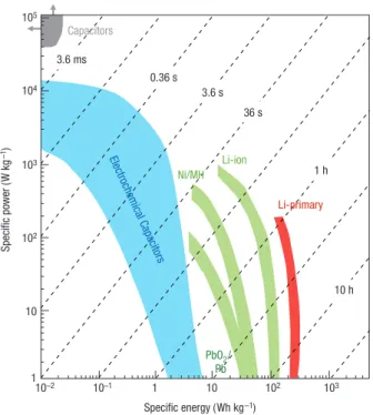
their performance substantially to meet the higher requirements of future systems, ranging from portable electronics to hybrid electric vehicles and large industrial equipment, by developing new materials and advancing our understanding of the electrochemical interfaces at the nanoscale. Figure 1 shows the plot of power against energy density, also called a Ragone plot2, for the most important energy
storage systems.
Lithium-ion batteries were introduced in 1990 by Sony, following pioneering work by Whittingham, Scrosati and Armand (see ref. 3 for a review). These batteries, although costly, are the best in terms of performance, with energy densities that can reach 180 watt hours
per kilogram. Although great efforts have gone into developing high-performance Li-ion and other advanced secondary batteries that use nanomaterials or organic redox couples4–6, ECs have
attracted less attention until very recently. Because Li-ion batteries suffer from a somewhat slow power delivery or uptake, faster and higher-power energy storage systems are needed in a number of applications, and this role has been given to the ECs7. Also known
as supercapacitors or ultracapacitors, ECs are power devices that can be fully charged or discharged in seconds; as a consequence, their energy density (about 5 Wh kg–1) is lower than in batteries, but a
much higher power delivery or uptake (10 kW kg–1) can be achieved
for shorter times (a few seconds)1. They have had an important role
in complementing or replacing batteries in the energy storage field, such as for uninterruptible power supplies (back-up supplies used to protect against power disruption) and load-levelling. A more recent example is the use of electrochemical double layer capacitors (EDLCs) in emergency doors (16 per plane) on an Airbus A380, thus proving that in terms of performance, safety and reliability ECs are definitely ready for large-scale implementation. A recent report by the US Department of Energy8 assigns equal importance to supercapacitors
and batteries for future energy storage systems, and articles on supercapacitors appearing in business and popular magazines show increasing interest by the general public in this topic.
Several types of ECs can be distinguished, depending on the charge storage mechanism as well as the active materials used. EDLCs, the most common devices at present, use carbon-based active materials with high surface area (Fig. 2). A second group of ECs, known as pseudo-capacitors or redox supercapacitors, uses fast and reversible surface or near-surface reactions for charge storage. Transition metal oxides as well as electrically conducting polymers are examples of
Materials for electrochemical capacitors
Electrochemical capacitors, also called supercapacitors, store energy using either ion adsorption
(electrochemical double layer capacitors) or fast surface redox reactions (pseudo-capacitors). They
can complement or replace batteries in electrical energy storage and harvesting applications, when
high power delivery or uptake is needed. A notable improvement in performance has been achieved
through recent advances in understanding charge storage mechanisms and the development of
advanced nanostructured materials. The discovery that ion desolvation occurs in pores smaller than
the solvated ions has led to higher capacitance for electrochemical double layer capacitors using
carbon electrodes with subnanometre pores, and opened the door to designing high-energy density
devices using a variety of electrolytes. Combination of pseudo-capacitive nanomaterials, including
oxides, nitrides and polymers, with the latest generation of nanostructured lithium electrodes has
brought the energy density of electrochemical capacitors closer to that of batteries. The use of carbon
nanotubes has further advanced micro-electrochemical capacitors, enabling flexible and adaptable
devices to be made. Mathematical modelling and simulation will be the key to success in designing
tomorrow’s high-energy and high-power devices.
pseudo-capacitive active materials. Hybrid capacitors, combining a capacitive or pseudo-capacitive electrode with a battery electrode, are the latest kind of EC, which benefit from both the capacitor and the battery properties.
Electrochemical capacitors currently fill the gap between batteries and conventional solid state and electrolytic capacitors (Fig. 1). They store hundreds or thousands of times more charge (tens to hundreds of farads per gram) than the latter, because of a much larger surface area (1,000–2,000 m2 g–1) available for charge storage in EDLC.
However, they have a lower energy density than batteries, and this limits the optimal discharge time to less than a minute, whereas many applications clearly need more9. Since the early days of EC
development in the late 1950s, there has not been a good strategy for increasing the energy density; only incremental performance improvements were achieved from the 1960s to 1990s. The impressive increase in performance that has been demonstrated in the past couple of years is due to the discovery of new electrode materials and improved understanding of ion behaviour in small pores, as well as the design of new hybrid systems combining faradic and capacitive electrodes. Here we give an overview of past and recent findings as well as an analysis of what the future holds for ECs.
electrochemical double-laYer caPacitorS
The first patent describing the concept of an electrochemical capacitor was filed in 1957 by Becker9, who used carbon with a high specific
surface area (SSA) coated on a metallic current collector in a sulphuric acid solution. In 1971, NEC (Japan) developed aqueous-electrolyte capacitors under the energy company SOHIO’s licence for power-saving units in electronics, and this application can be considered as the starting point for electrochemical capacitor use in commercial devices9. New applications in mobile electronics, transportation
(cars, trucks, trams, trains and buses), renewable energy production and aerospace systems10 bolstered further research.
mechaniSm of double-laYer caPacitance
EDLCs are electrochemical capacitors that store the charge electrostatically using reversible adsorption of ions of the electrolyte onto active materials that are electrochemically stable and have high accessible SSA. Charge separation occurs on polarization at the electrode–electrolyte interface, producing what Helmholtz described in 1853 as the double layer capacitance C:
C or d (1) εrε0A C/A d εrε0 = = (1)
where εr is the electrolyte dielectric constant, ε0 is the dielectric
constant of the vacuum, d is the effective thickness of the double layer (charge separation distance) and A is the electrode surface area.
This capacitance model was later refined by Gouy and Chapman, and Stern and Geary, who suggested the presence of a diffuse layer in the electrolyte due to the accumulation of ions close to the electrode surface. The double layer capacitance is between 5 and 20 µF cm–2
depending on the electrolyte used11. Specific capacitance achieved
with aqueous alkaline or acid solutions is generally higher than in organic electrolytes11, but organic electrolytes are more widely used as
they can sustain a higher operation voltage (up to 2.7 V in symmetric systems). Because the energy stored is proportional to voltage squared according to
E = ½ CV2 (2)
a three-fold increase in voltage, V, results in about an order of magnitude increase in energy, E, stored at the same capacitance.
As a result of the electrostatic charge storage, there is no faradic (redox) reaction at EDLC electrodes. A supercapacitor electrode must be considered as a blocking electrode from an electrochemical point of view. This major difference from batteries means that there is no limitation by the electrochemical kinetics through a polarization resistance. In addition, this surface storage mechanism allows very fast energy uptake and delivery, and better power performance. The absence of faradic reactions also eliminates the swelling in the active material that batteries show during charge/discharge cycles. EDLCs can sustain millions of cycles whereas batteries survive a few thousand at best. Finally, the solvent of the electrolyte is not involved in the charge storage mechanism, unlike in Li-ion batteries where it contributes to the solid–electrolyte interphase when graphite anodes or high-potential cathodes are used. This does not limit the choice of solvents, and electrolytes with high power performances at low temperatures (down to –40 °C) can be designed for EDLCs. However, as a consequence of the electrostatic surface charging mechanism, these devices suffer from a limited energy density. This explains why today’s EDLC research is largely focused on increasing their energy performance and widening the temperature limits into the range where batteries cannot operate9.
hiGh Surface area active materialS
The key to reaching high capacitance by charging the double layer is in using high SSA blocking and electronically conducting electrodes. Graphitic carbon satisfies all the requirements for this application, including high conductivity, electrochemical stability and open porosity12. Activated, templated and carbide-derived carbons13,
carbon fabrics, fibres, nanotubes14, onions15 and nanohorns16 have
been tested for EDLC applications11, and some of these carbons are
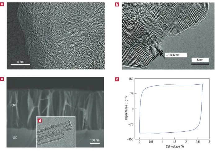
shown in Fig. 2a–d. Activated carbons are the most widely used materials today, because of their high SSA and moderate cost.
Activated carbons are derived from carbon-rich organic precursors by carbonization (heat treatment) in inert atmosphere
Li-primary Specific power (W kg –1) Specific energy (Wh kg–1) Capacitors Pb 36 s 0.36 s 3.6 ms 1 h 10 h 3.6 s 10–2 102 102 103 103 104 105 10–1 1 1 10 10 Ni/MH Li-ion Electr ochemical Capacitor s PbO2/
Figure 1 Specific power against specific energy, also called a ragone plot, for
various electrical energy storage devices. if a supercapacitor is used in an electric vehicle, the specific power shows how fast one can go, and the specific energy shows how far one can go on a single charge. times shown are the time constants of the devices, obtained by dividing the energy density by the power.
with subsequent selective oxidation in CO2, water vapour or
KOH to increase the SSA and pore volume. Natural materials, such as coconut shells, wood, pitch or coal, or synthetic materials, such as polymers, can be used as precursors. A porous network in the bulk of the carbon particles is produced after activation; micropores (<2 nm in size), mesopores (2–50 nm) and macropores (>50 nm) can be created in carbon grains. Accordingly, the porous structure of carbon is characterized by a broad distribution of pore size. Longer activation time or higher temperature leads to larger mean pore size. The double layer capacitance of activated carbon reaches 100–120 F g–1 in organic electrolytes; this value can
exceed 150–300 F g–1 in aqueous electrolytes, but at a lower cell
voltage because the electrolyte voltage window is limited by water decomposition. A typical cyclic voltammogram of a two-electrode EDLC laboratory cell is presented in Fig. 2e. Its rectangular shape is characteristic of a pure double layer capacitance mechanism for charge storage according to:
(3)
I = C × dVdt (3) where Ι is the current, (dV/dt) is the potential scan rate and C is the double layer capacitance. Assuming a constant value for C, for a given scan rate the current I is constant, as can be seen from Fig. 2e, where the cyclic voltammogram has a rectangular shape. As previously mentioned, many carbons have been tested for EDLC applications and a recent paper11 provides an overview
of
what has been achieved. Untreated carbon nanotubes17 or nanofibres
have a lower capacitance (around 50–80 F g–1) than activated carbon
in organic electrolytes. It can be increased up to 100 F g–1 or greater
by grafting oxygen-rich groups, but these are often detrimental to cyclability. Activated carbon fabrics can reach the same capacitance as activated carbon powders, as they have similar SSA, but the high price limits their use to speciality applications. The carbons used in EDL capacitors are generally pre-treated to remove moisture and most of the surface functional groups present on the carbon surface to improve stability during cycling, both of which can be responsible for capacitance fading during capacitor ageing as demonstrated by Azais et al.18 using NMR and X-ray photoelectron spectroscopy
techniques. Pandolfo et al.11, in their review article, concluded that
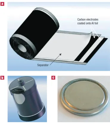
the presence of oxygenated groups also contributes to capacitor instability, resulting in an increased series resistance and deterioration of capacitance. Figure 3 presents a schematic of a commercial EDLC, showing the positive and the negative electrodes as well as the separator in rolled design (Fig. 3a,b) and flat design (button cell in Fig. 3c).
caPacitance and Pore Size
Initial research on activated carbon was directed towards increasing the pore volume by developing high SSA and refining the activation process. However, the capacitance increase was limited even for the most porous samples. From a series of activated carbons with different pore sizes in various electrolytes, it was shown that there was no linear relationship between the SSA and the capacitance19–21. Some
5 nm 5 nm ~0.336 nm
3)
SiC CNT –75 0 75 150 Capacitance (F g –1) 100 nm Cell voltage (V) 0 0.5 1 1.5 2 2.5 3 –150Figure 2 carbon structures used as active materials for double layer capacitors. a, typical transmission electronic microscopy (tem) image of a disordered microporous
carbon (Sic-derived carbon, 3 hours chlorination at 1,000 °c). b, tem image of onion-like carbon. reproduced with permission from ref. 80. © 2007 elsevier. c, Scanning
electron microscopy image of an array of carbon nanotubes (labelled cnt) on Sic produced by annealing for 6 h at 1,700 °c; inset, d, shows a tem image of the same
nanotubes72. e, cyclic voltammetry of a two-electrode laboratory edlc cell in 1.5 m tetraethylammonium tetrafluoroborate net
4+,bf4– in acetonitrile-based electrolyte,
studies suggested that pores smaller than 0.5 nm were not accessible to hydrated ions20,22 and that even pores under 1 nm might be too
small, especially in the case of organic electrolytes, where the size of the solvated ions is larger than 1 nm (ref. 23). These results were consistent with previous work showing that ions carry a dynamic sheath of solvent molecules, the solvation shell24, and that some
hundreds of kilojoules per mole are required to remove it25 in the
case of water molecules. A pore size distribution in the range 2–5 nm, which is larger than the size of two solvated ions, was then identified as a way to improve the energy density and the power capability. Despite all efforts, only a moderate improvement has been made. Gravimetric capacitance in the range of 100–120 F g–1 in organic and 150–200 F g–1
in aqueous electrolytes has been achieved26,27 and ascribed to improved
ionic mass transport inside mesopores. It was assumed that a well balanced micro- or mesoporosity (according to IUPAC classification, micropores are smaller than 2 nm, whereas mesopores are 2–50 nm in diameter) was needed to maximize capacitance28.
Although fine-tuned mesoporous carbons failed to achieve high capacitance performance, several studies reported an important capacitive contribution from micropores. From experiments using activated carbon cloth, Salitra et al.29 suggested that a partial
desolvation of ions could occur, allowing access to small pores (<2 nm). High capacitance was observed for a mesoporous carbon containing large numbers of small micropores30–32, suggesting that
partial ion desolvation could lead to an improved capacitance. High capacitances (120 F g–1 and 80 F cm–3) were found in organic
electrolytes for microporous carbons (<1.5 nm)33,34, contradicting
the solvated ion adsorption theory. Using microporous activated coal-based carbon materials, Raymundo-Pinero et al.35 observed the
same effect and found a maximum capacitance for pore size at 0.7 and
0.8 nm for aqueous and organic electrolytes, respectively. However, the most convincing evidence of capacitance increase in pores smaller than the solvated ion size was provided by experiments using carbide-derived carbons (CDCs)36–38 as the active material. These are porous
carbons obtained by extraction of metals from carbides (TiC, SiC and other) by etching in halogens at elevated temperatures39:
TiC + 2Cl2 → TiCl4 + C (4)
In this reaction, Ti is leached out from TiC, and carbon atoms self-organize into an amorphous or disordered, mainly sp2-bonded40,
structure with a pore size that can be fine-tuned by controlling the chlorination temperature and other process parameters. Accordingly, a narrow uni-modal pore size distribution can be achieved in the range 0.6–1.1 nm, and the mean pore size can be controlled with sub-ångström accuracy41. These materials were used to understand
the charge storage in micropores using 1 M solution of NEt4BF4
in acetonitrile-based electrolyte42. The normalized capacitance
(µF cm–²) decreased with decreasing pore size until a critical value
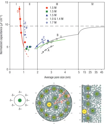
close to 1 nm was reached (Fig. 4), and then sharply increased when the pore size approached the ion size. As the CDC samples were exclusively microporous, the capacitance increase for subnanometre pores clearly shows the role of micropores. Moreover, the gravimetric and volumetric capacitances achieved by CDC were, respectively, 50% and 80% higher than for conventional activated carbon19–21.
The capacitance change with the current density was also found to be stable, demonstrating the high power capabilities these materials can achieve42. As the solvated ion sizes in this electrolyte were 1.3 and
1.16 nm for the cation and anion16, respectively, it was proposed that
partial or complete removal of their solvation shell was allowing the ions to access the micropores. As a result, the change of capacitance was a linear function of 1/b (where b is the pore radius), confirming that the distance between the ion and the carbon surface, d, was shorter for the smaller pores. This dependence published by Chmiola et al.42
has since been confirmed by other studies, and analysis of literature data is provided in refs 43 and 44.
charGe-StoraGe mechaniSm in Subnanometre PoreS
From a fundamental point of view, there is a clear lack of understanding of the double layer charging in the confined space of micropores, where there is no room for the formation of the Helmholtz layer and diffuse layer expected at a solid–electrolyte interface. To address this issue, a three-electrode cell configuration, which discriminates between anion and cation adsorption, was used45. The double layer capacitance in
1.5 M NEt4BF4-acetonitrile electrolyte caused by the anion and cation
at the positive and negative electrodes, respectively, had maxima at different pore sizes45. The peak in capacitance shifted to smaller pores
for the smaller ion (anion). This behaviour cannot be explained by purely electrostatic reasons, because all pores in this study were the same size as or smaller than a single ion with a single associated solvent molecule. It thus confirmed that ions must be at least partially stripped of solvent molecules in order to occupy the carbon pores. These results point to a charge storage mechanism whereby partial or complete removal of the solvation shell and increased confinement of ions lead to increased capacitance.
A theoretical analysis published by Huang et al.43 proposed splitting
the capacitive behaviour in two different parts depending on the pore size. For mesoporous carbons (pores larger than 2 nm), the traditional model describing the charge of the double layer was used43:
b ln b – db
εrε0 (5)
C/A = (5)
where b is the pore radius and d is the distance of approach of the ion to the carbon surface. Data from Fig. 4 in the mesoporous range
Carbon electrodes coated onto Al foil
Separator
Figure 3 electrochemical capacitors. a, Schematic of a commercial spirally wound
double layer capacitor. b, assembled device weighing 500 g and rated for 2,600 f.
(Photo courtesy of batscap, Groupe bolloré, france.) c, a small button cell, which is
just 1.6 mm in height and stores 5 f. (Photo courtesy of Y-carbon, uS.) both devices operate at 2.7 v.
(zone III) were fitted with equation (5). For micropores (<1 nm), it was assumed that ions enter a cylindrical pore and line up, thus forming the ‘electric wire in cylinder’ model of a capacitor. Capacitance was calculated from43
b ln b
εrε0 (6)
C/A = (6)
a0
where a0 is the effective size of the ion (desolvated). This
model perfectly matches with the normalized capacitance change versus pore size (zone I in Fig. 4). Calculations using density functional theory gave consistent values for the size, a0, for
unsolvated NEt4+ and BF4– ions43.
This work suggests that removal of the solvation shell is required for ions to enter the micropores. Moreover, the ionic radius a0 found by using equation (6) was close to the bare ion
size, suggesting that ions could be fully desolvated. A study carried out with CDCs in a
solvent-free electrolyte ([EMI+,TFSI–] ionic liquid at 60 °C), in which
both ions have a maximum size of about 0.7 nm, showed the maximum capacitance for samples with the 0.7-nm pore size46, demonstrating
that a single ion per pore produces the maximum capacitance (Fig. 5). This suggests that ions cannot be adsorbed on both pore surfaces, in contrast with traditional supercapacitor models.
materialS bY deSiGn
The recent findings of the micropore contribution to the capacitive storage highlight the lack of fundamental understanding of the electrochemical interfaces at the nanoscale and the behaviour of ions confined in nanopores. In particular, the results presented above rule out the generally accepted description of the double layer with solvated ions adsorbed on both sides of the pore walls, consistent with the absence of a diffuse layer in subnanometre pores. Although recent studies45,46 provide some guidance for
developing materials with improved capacitance, such as elimination of macro- and mesopores and matching the pore size with the ion size, further material optimization by Edisonian or combinatorial electrochemistry methods may take a very long time. The effects of many parameters, such as carbon bonding (sp versus sp2 or sp3), pore
shape, defects or adatoms, are difficult to determine experimentally. Clearly, computational tools and atomistic simulation will be needed to help us to understand the charge storage mechanism in subnanometre pores and to propose strategies to design the next generation of high-capacitance materials and material–electrolyte systems47. Recasting the theory of double layers in electrochemistry
to take into account solvation and desolvation effects could lead to a better understanding of charge storage as well as ion transport in ECs and even open up new opportunities in areas such as biological ion channels and water desalination.
redox-baSed electrochemical caPacitorS
mechaniSm of PSeudo-caPacitive charGe StoraGe
Some ECs use fast, reversible redox reactions at the surface of active materials, thus defining what is called the pseudo-capacitive behaviour. Metal oxides such as RuO2, Fe3O4 or MnO2 (refs 48, 49),
as well as electronically conducting polymers50, have been extensively
studied in the past decades. The specific pseudo-capacitance exceeds
0 5 10 15 1.5 M 1.5 M 1.5 M 1.0 & 1.4 M 1.7 M I IV D E F C B A
Average pore size (nm)
0 1 2 3 4 5 15 25 35 45 II III Normalized capacitance (µ F cm –2) + δ– δ– δ– δ– δ– δ– δ– δ– – – – – – – – – – – – – b d a – – – – – –
Figure 4 Specific capacitance normalized by SSa as a function of pore size for
different carbon samples. all samples were tested in the same electrolyte (net4+,bf4–
in acetonitrile; concentrations are shown in the key). Symbols show experimental data for cdcs, templated mesoporous carbons and activated carbons, and lines show model fits43. a huge normalized capacitance increase is observed for microporous
carbons with the smallest pore size in zone i, which would not be expected in the traditional view. the partial or complete loss of the solvation shell explains this anomalous behaviour42. as schematics show, zones i and ii can be modelled as an
electric wire-in-cylinder capacitor, an electric double-cylinder capacitor should be considered for zone iii, and the commonly used planar electric double layer capacitor can be considered for larger pores, when the curvature/size effect becomes negligible (zone iv). a mathematical fit in the mesoporous range (zone iii) is obtained using equation (5). equation (6) was used to model the capacitive behaviour in zone i, where confined micropores force ions to desolvate partially or completely44. a, b:
templated mesoporous carbons; c: activated mesoporous carbon; d, f: microporous cdc; e: microporous activated carbon. reproduced with permission from ref. 44. © 2008 Wiley. Normalized capacitance (μ F cm 2) 0.6 6 7 8 9 10 11 12 13 4.3 Å 7.6 Å 7.9 Å 2.9 Å EMI cation TFSI anion 14 0.7 0.8 Pore size (nm)0.9 1 – + 1.1 Fluorine Carbon Nitrogen Hydrogen Oxygen Sulphur H H H H H H H H F F F F F F O N C O O S S C O H C C C C C C N N
Figure 5 normalized capacitance change as a function of the pore size of
carbon-derived-carbide samples. Samples were prepared at different temperatures in ethyl-methylimidazolium/trifluoro-methane-sulphonylimide (emi,tfSi) ionic liquid at 60 °c. inset shows the structure and size of the emi and tfSi ions. the maximum capacitance is obtained when the pore size is in the same range as the maximum ion dimension. reproduced with permission from ref. 46. © 2008 acS.
that of carbon materials using double layer charge storage, justifying interest in these systems. But because redox reactions are used, pseudo-capacitors, like batteries, often suffer from a lack of stability during cycling.
Ruthenium oxide, RuO2, is widely studied because it is conductive
and has three distinct oxidation states accessible within 1.2 V. The pseudo-capacitive behaviour of RuO2 in acidic solutions has been the
focus of research in the past 30 years1. It can be described as a fast,
reversible electron transfer together with an electro-adsorption of protons on the surface of RuO2 particles, according to equation (7),
where Ru oxidation states can change from (ii) up to (iv):
RuO2 + xH+ + xe– ↔ RuO2–x(OH)x (7)
where 0 ≤ x ≤ 2. The continuous change of x during proton insertion or de-insertion occurs over a window of about 1.2 V and leads to a capacitive behaviour with ion adsorption following a Frumkin-type isotherm1. Specific capacitance of more than 600 F g–1 has been
reported51, but Ru-based aqueous electrochemical capacitors are
expensive, and the 1-V voltage window limits their applications to small electronic devices. Organic electrolytes with proton surrogates (for example Li+) must be used to go past 1 V. Less expensive oxides
of iron, vanadium, nickel and cobalt have been tested in aqueous electrolytes, but none has been investigated as much as manganese oxide52. The charge storage mechanism is based on surface adsorption
of electrolyte cations C+ (K+, Na+…) as well as proton incorporation
according to the reaction:
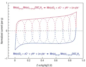
MnO2 + xC+ + yH+ + (x+y)e– ↔ MnOOCxHy (8)
Figure 6 shows a cyclic voltammogram of a single MnO2 electrode in
mild aqueous electrolyte; the fast, reversible successive surface redox reactions define the behaviour of the voltammogram, whose shape is close to that of the EDLC. MnO2 micro-powders or micrometre-thick
films show a specific capacitance of about 150 F g–1 in neutral aqueous
electrolytes within a voltage window of <1 V. Accordingly, there is limited interest in MnO2 electrodes for symmetric devices, because
there are no oxidation states available at less than 0 V. However, it is suitable for a pseudo-capacitive positive electrode in hybrid systems,
which we will describe below. Other transition metal oxides with various oxidation degrees, such as molybdenum oxides, should also be explored as active materials for pseudo-capacitors.
Many kinds of conducting polymers (polyaniline, polypyrrole, polythiophene and their derivatives) have been tested in EC applications as pseudo-capacitive materials50,53,54 and have shown
high gravimetric and volumetric pseudo-capacitance in various non-aqueous electrolytes at operating voltages of about 3 V. When used as bulk materials, conducting polymers suffer from a limited stability during cycling that reduces the initial performance9. Research
efforts with conducting polymers for supercapacitor applications are nowadays directed towards hybrid systems.
nanoStructurinG redox-active materialS to increaSe caPacitance
Given that nanomaterials have helped to improve Li-ion batteries55, it
is not surprising that nanostructuring has also affected ECs. Because pseudo-capacitors store charge in the first few nanometres from the surface, decreasing the particle size increases active material usage. Thanks to a thin electrically conducting surface layer of oxide and oxynitride, the charging mechanism of nanocrystalline vanadium nitride (VN) includes a combination of an electric double layer and a faradic reaction (ii/iv) at the surface of the nanoparticles, leading to specific capacitance up to 1,200 F g–1 at a scan rate of 2 mV s–1
(ref. 56). A similar approach can be applied to other nano-sized transition metal nitrides or oxides. In another example, the cycling stability and the specific capacitance of RuO2 nanoparticles were
increased by depositing a thin conducting polymer coating that enhanced proton exchange at the surface57. The design of specific
surface functionalization to improve interfacial exchange could be suggested as a generic approach to other pseudo-redox materials.
MnO2 and RuO2 films have been synthesized at the nanometre
scale. Thin MnO2 deposits of tens to hundreds of nanometres have
been produced on various substrates such as metal collectors, carbon nanotubes or activated carbons. Specific capacitances as high as 1,300 F g–1 have been reported58, as reaction kinetics were no
longer limited by the electrical conductivity of MnO2. In the same
way, Sugimoto’s group have prepared hydrated RuO2 nano-sheets
with capacitance exceeding 1,300 F g–1 (ref. 59). The RuO
2 specific
capacitance also increased sharply when the film thickness was decreased. The deposition of RuO2 thin film onto carbon supports60,61
both increased the capacitance and decreased the RuO2 consumption.
Thin film synthesis or high SSA capacitive material decoration with nano-sized pseudo-capacitive active material, like the examples presented in Fig. 7a and b, offers an opportunity to increase energy density and compete with carbon-based EDLCs. Particular attention must be paid to further processing of nano-sized powders into active films because they tend to re-agglomerate into large-size grains. An alternative way to produce porous films from powders is by growing nanotubes, as has been shown for V2O5 (ref. 62), or nanorods. These
allow easy access to the active material, but can only be produced in thin films so far, and the manufacturing cost will probably limit the use of these sophisticated nanostructures to small electronic devices.
hYbrid SYStemS to achieve hiGh enerGY denSitY
Hybrid systems offer an attractive alternative to conventional pseudo-capacitors or EDLCs by combining a battery-like electrode (energy source) with a capacitor-like electrode (power source) in the same cell. An appropriate electrode combination can even increase the cell voltage, further contributing to improvement in energy and power densities. Currently, two different approaches to hybrid systems have emerged: (i) pseudo-capacitive metal oxides with a capacitive carbon electrode, and (ii) lithium-insertion electrodes with a capacitive carbon electrode.
Numerous combinations of positive and negative electrodes have been tested in the past in aqueous or inorganic electrolytes. In most
NormaIized current (per g)
0 –1 0 1 0.2 0.4 0.6 0.8 1.0 E vs Ag/AgCl (V)
Mn(III)(x+y),Mn(IV)1–(x+y)OOCxHy Mn(IV)O2 + xC+ + yH+ + (x+y)e–
Mn(IV)O2 + xC+ + yH+ + (x+y)e– Mn(III)(x+y), Mn(IV)1–(x+y)OOCxHy
Figure 6 cyclic voltammetry. this schematic of cyclic voltammetry for a mno2
-electrode cell in mild aqueous electrolyte (0.1 m K2So4) shows the successive
multiple surface redox reactions leading to the pseudo-capacitive charge storage mechanism. the red (upper) part is related to the oxidation from mn(iii) to mn(iv) and
cases, the faradic electrode led to an increase in the energy density at the cost of cyclability (for balanced positive and negative electrode capacities). This is certainly the main drawback of hybrid devices, as compared with EDLCs, and it is important to avoid transforming a good supercapacitor into a mediocre battery63.
MnO2 is one of the most studied materials as a low-cost alternative
to RuO2. Its pseudo-capacitance arises from the iii/iv oxidation state
change at the surface of MnO2 particles58. The association of a negative
EDLC-type electrode with a positive MnO2 electrode leads to a 2-V cell
in aqueous electrolytes thanks to the apparent water decomposition overvoltage on MnO2 and high-surface-area carbon. The low-cost
carbon–MnO2 hybrid system combines high capacitance in neutral
aqueous electrolytes with high cell voltages, making it a green alternative to EDLCs using acetonitrile-based solvents and fluorinated salts. Moreover, the use of MnO2 nano-powders and nanostructures
offers the potential for further improvement in capacitance64. Another
challenge for this system is to use organic electrolytes to reach higher cell voltage, thus improving the energy density.
A combination of a carbon electrode with a PbO2 battery-like
electrode using H2SO4 solution can work at 2.1 V (ref. 65), offering a
low-cost EC device for cost-sensitive applications, in which weight of the device is of minor concern.
The hybrid concept originated from the Li-ion batteries field. In 1999, Amatucci’s group combined a nanostructured lithium titanate anode Li4Ti5O12 with an activated carbon positive electrode, designing
a 2.8-V system that for the first time exceeded 10 Wh kg–1 (ref. 66).
The titanate electrode ensured high power capacity and no solid-electrolyte interphase formation, as well as long-life cyclability thanks to low volume change during cycling. Following this pioneering
work, many studies have been conducted on various combinations of a lithium-insertion electrode with a capacitive carbon electrode. The Li-ion capacitor developed by Fuji Heavy Industry is an example of this concept, using a pre-lithiated high SSA carbon anode together with an activated carbon cathode63,67. It achieved an energy density
of more than 15 Wh kg–1 at 3.8 V. Capacity retention was increased
by unbalancing the electrode capacities, allowing a low depth of charge/discharge at the anode. Systems with an activated carbon anode and anion intercalation cathode are also under development. The advent of nanomaterials55 as well as fast advances in the area of
Li-ion batteries should lead to the design of high-performance ECs. Combining newly developed high-rate conversion reaction anodes or Li-alloying anodes with a positive supercapacitor electrode could fill the gap between Li-ion batteries and EDLCs. These systems could be of particular interest in applications where high power and medium cycle life are needed.
current collectorS
Because ECs are power devices, their internal resistance must be kept low. Particular attention must be paid to the contact impedance between the active film and the current collector. ECs designed for organic electrolytes use treated aluminium foil or grid current collectors. Surface treatments have already been shown to decrease ohmic drops at this interface68, and coatings on aluminium that
improve electrochemical stability at high potentials and interface conductivity are of great interest.
The design of nanostructured current collectors with an increased contact area is another way to control the interface between current
Activated carbon grain
Activated carbon grain
Carbon nanotubes or rods
Pseudo-capacitive material
Pseudo-capacitive material
Current collector Current collector
Current collector Current collector
Figure 7 Possible strategies to improve both energy and power densities for electrochemical capacitors. a, b, decorating activated carbon grains (a) with pseudo-capacitive
collector and active material. For example, carbon can be produced in a variety of morphologies12, including porous films and nanotube
brushes that can be grown on various current collectors69 and that
can serve as substrates for further conformal deposition (Fig. 7c and d) of active material. These nano-architectured electrodes could outperform the existing systems by confining a highly pseudo-capacitive material to a thin film with a high SSA, as has been done for Li-ion batteries70 where, by growing Cu nano-pillars on a planar
Cu foil, a six-fold improvement in the energy density over planar electrodes has been achieved70. Long’s group64 successfully applied
a similar approach to supercapacitors by coating a porous carbon nano-foam with a 20-nm pseudo-capacitive layer of MnO2. As a
result, the area-normalized capacitance doubled to reach 1.5 F cm–2,
together with an outstanding volumetric capacitance of 90 F cm–3.
Electrophoretic deposition from stable colloidal suspensions of RuO2
(ref.71) or other active material can be used for filling the inter-tube space to design high-energy-density devices which are just a few micrometres thick. The nano-architectured electrodes also find applications in micro-systems where micro-ECs can complement micro-batteries for energy harvesting or energy generation. In this specific field, it is often advantageous to grow self-supported, binder-less nano-electrodes directly on semiconductor wafers, such as Si or SiC (ref. 72; Fig. 2c).
An attractive material for current collectors is carbon in the form of a highly conductive nanotube or graphene paper. It does not corrode in aqueous electrolytes and is very flexible. The use of nanotube paper for manufacturing flexible supercapacitors is expected to grow as the cost of small-diameter nanotubes required for making paper decreases. The same thin sheet of nanotubes14 could potentially act as
an active material and current collector at the same time. Thin-film, printable and wearable ECs could find numerous applications.
from orGanic to ionic liquid electrolYteS
EC cell voltage is limited by the electrolyte decomposition at high potentials. Accordingly, the larger the electrolyte stability voltage window, the higher the supercapacitor cell voltage. Moving from aqueous to organic electrolytes increased the cell voltage from 0.9 V to 2.5–2.7 V for EDLCs. Because the energy density is proportional to the voltage squared (equation (2)), numerous research efforts have been directed at the design of highly conducting, stable electrolytes with a wider voltage window. Today, the state of the art is the use of organic electrolyte solutions in acetonitrile or propylene carbonate, the latter becoming more popular because of the low flash point and lower toxicity compared with acetonitrile.
Ionic liquids are room-temperature liquid solvent-free electrolytes; their voltage window stability is thus only driven by the electrochemical stability of the ions. A careful choice of both the anion and the cation allows the design of high-voltage supercapacitors, and 3-V, 1,000-F commercial devices are already available73. However,
the ionic conductivity of these liquids at room temperature is just a few milliSiemens per centimetre, so they are mainly used at higher temperatures. For example, CDC with an EMI/TFSI ionic liquid electrolyte has been shown46 to have capacitance of 160 F g–1 and
~90 F cm–3 at 60 °C. In this area, hybrid activated carbon/conducting
polymer devices also show an improved performance with cell voltages higher than 3 V (refs 74–76).
For applications in the temperature range –30 °C to +60 °C, where batteries and supercapacitors are mainly used, ionic liquids still fail to satisfy the requirements because of their low ionic conductivity. However, the choice of a huge variety of combinations of anions and cations offers the potential for designing an ionic liquid electrolyte with an ionic conductivity of 40 mS cm–1 and a voltage window of
>4 V at room temperature77. A challenge is, for instance, to find an
alternative to the imidazolium cation that, despite high conductivity,
undergoes a reduction reaction at potential <1.5 V versus Li+/Li.
Replacing the heavy bis(trifluoromethanesulphonyl)imide (TFSI) anion by a lighter (fluoromethanesulphonyl)imide (FSI) and preparing ionic liquid eutectic mixtures would improve both the cell voltage (because a protecting layer of AlF3 can be formed on the Al
surface, shifting the de-passivation potential of Al above 4 V) and the ionic conductivity77. However, FSI shows poor cyclability at elevated
temperatures. Supported by the efforts of the Li-ion community to design safer systems using ionic liquids, the research on ionic liquids for ECs is expected to have an important role in the improvement of capacitor performance in the coming years.
aPPlicationS of electrochemical caPacitorS
ECs are electrochemical energy sources with high power delivery and uptake, with an exceptional cycle life. They are used when high power demands are needed, such as for power buffer and power saving units, but are also of great interest for energy recovery. Recent articles from Miller et al.7,10 present an overview of the opportunities
for ECs in a variety of applications, complementing an earlier review by Kötz et al.9. Small devices (a few farads) are widely used for
power buffer applications or for memory back-up in toys, cameras, video recorders, mobile phones and so forth. Cordless tools such as screwdrivers and electric cutters using EDLCs are already available on the market. Such systems, using devices of a few tens of farads, can be fully charged or discharged in less than 2 minutes, which is particularly suited to these applications, with the cycle life of EDLC exceeding that of the tool. As mentioned before, the Airbus A380 jumbo jets use banks of EDLCs for emergency door opening. The modules consist of an in series/parallel assembly of 100-F, 2.7-V cells that are directly integrated into the doors to limit the use of heavy copper cables. This application is obviously a niche market, but it is a demonstration that the EDLC technology is mature in terms of performance, reliability and safety.
The main market targeted by EDLC manufacturers for the next years is the transportation market, including hybrid electric vehicles, as well as metro trains and tramways. There continues to be debate about the advantage of using high power Li-ion batteries instead of ECs (or vice versa) for these applications. Most of these discussions have been initiated by Li-ion battery manufacturers who would like their products to cover the whole range of applications. However, ECs and Li-ion batteries should not necessarily be seen as competitors, because their charge storage mechanisms and thus their characteristics are different. The availability of the stored charge will always be faster for a supercapacitor (surface storage) than for a Li-ion battery (bulk storage), with a larger stored energy for the latter. Both devices must be used in their respective time-constant domains (see Fig. 1). Using a Li-ion battery for repeated high power delivery/uptake applications for a short duration (10 s or less) will quickly degrade the cycle life of the system10. The only way to avoid this is to oversize the battery, increasing
the cost and volume. In the same way, using ECs for power delivery longer than 10 s requires oversizing. However, some applications use ECs as the main power and energy source, benefiting from the fast charge/discharge capability of these systems as well as their outstanding cycle life. Several train manufacturers have clearly identified the tramway/metro market segment as extremely relevant for EC use, to power trains over short distances in big cities, where electric cables are clearly undesirable for aesthetic and other reasons, but also to recover the braking energy of another train on the same line, thanks to the ECs’ symmetric high power delivery/uptake characteristics.
For automotive applications, manufacturers are already proposing solutions for electrical power steering, where ECs are used for load-levelling in stop-and-go traffic78. The general trend is to increase
the hybridization degree of the engines in hybrid electric vehicles, to allow fast acceleration (boost) and braking energy recovery. The
on-board energy storage systems will be in higher demand, and a combination of batteries and EDLCs will increase the battery cycle life, explaining why EDLCs are viewed as a partner to Li-ion batteries for this market78. Currently, high price limits the use of both Li-ion
batteries and EDLC in large-scale applications (for example for load levelling). But the surprisingly high cost of materials used for EDLC is due to a limited number of suppliers rather than intrinsically high cost of porous carbon. Decreasing the price of carbon materials for ECs, including CDC and AC, would remove the main obstacle to their wider use79.
SummarY and outlooK
The most recent advances in supercapacitor materials include nanoporous carbons with the pore size tuned to fit the size of ions of the electrolyte with ångström accuracy, carbon nanotubes for flexible and printable devices with a short response time, and transition metal oxide and nitride nanoparticles for pseudo-capacitors with a high energy density. An improved understanding of charge storage and ion desolvation in subnanometre pores has helped to overcome a barrier that has been hampering progress in the field for decades. It has also shown how important it is to match the active materials with specific electrolytes and to use a cathode and anode with different pore sizes that match the anion or cation size. Nano-architecture of electrodes has led to further improvements in power delivery. The very large number of possible active materials and electrolytes means that better theoretical guidance is needed for the design of future ECs.
Future generations of ECs are expected to come close to current Li-ion batteries in energy density, maintaining their high power density. This may be achieved by using ionic liquids with a voltage window of more than 4 V, by discovering new materials that combine double-layer capacitance and pseudo-capacitance, and by developing hybrid devices. ECs will have a key role in energy storage and harvesting, decreasing the total energy consumption and minimizing the use of hydrocarbon fuels. Capacitive energy storage leads to a lower energy loss (higher cycle efficiency), than for batteries, compressed air, flywheel or other devices, helping to improve storage economy further. Flexible, printable and wearable ECs are likely to be integrated into smart clothing, sensors, wearable electronics and drug delivery systems. In some instances they will replace batteries, but in many cases they will either complement batteries, increasing their efficiency and lifetime, or serve as energy solutions where an extremely large number of cycles, long lifetime and fast power delivery are required.
doi:10.1038/nmat2297 references
1. Conway, B. E. Electrochemical Supercapacitors: Scientific Fundamentals and Technological
Applications (Kluwer, 1999).
2. Service, R. F. New ‘supercapacitor’ promises to pack more electrical punch. Science 313, 902–905 (2006). 3. Tarascon, J.-M. & Armand, M. Issues and challenges facing rechargeable lithium batteries. Nature
414, 359–367 (2001).
4. Brodd, R. J. et al. Batteries, 1977 to 2002. J. Electrochem. Soc. 151, K1–K11 (2004). 5. Armand, M. & Tarascon, J.-M. Building better batteries. Nature 451, 652–657 (2008). 6. Armand, M. & Johansson, P. Novel weakly coordinating heterocyclic anions for use in lithium
batteries. J. Power Sources 178, 821–825 (2008).
7. Miller, J. R. & Simon, P. Electrochemical capacitors for energy management. Science 321, 651–652 (2008).
8. US Department of Energy. Basic Research Needs for Electrical Energy Storage <www.sc.doe.gov/bes/ reports/abstracts.html#EES2007> (2007).
9. Kötz, R. & Carlen, M. Principles and applications of electrochemical capacitors. Electrochim. Acta 45, 2483–2498 (2000).
10. Miller, J. R. & Burke, A. F. Electrochemical capacitors: Challenges and opportunities for real-world applications. Electrochem. Soc. Interf. 17, 53–57 (2008).
11. Pandolfo, A. G. & Hollenkamp, A. F. Carbon properties and their role in supercapacitors.
J. Power Sources 157, 11–27 (2006).
12. Gogotsi, Y. (ed.) Carbon Nanomaterials (CRC, 2006).
13. Kyotani, T., Chmiola, J. & Gogotsi, Y. in Carbon Materials for Electrochemical Energy Storage Systems (eds Beguin, F. & Frackowiak, E.) Ch. 13 (CRC/Taylor and Francis, in the press).
14. Futaba, D. N. et al. Shape-engineerable and highly densely packed single-walled carbon nanotubes and their application as super-capacitor electrodes. Nature Mater. 5, 987–994 (2006). 15. Portet, C., Chmiola, J., Gogotsi, Y., Park, S. & Lian, K. Electrochemical characterizations of carbon
nanomaterials by the cavity microelectrode technique. Electrochim. Acta, 53, 7675–7680 (2008). 16. Yang, C.-M. et al. Nanowindow-regulated specific capacitance of supercapacitor electrodes of
single-wall carbon nanohorns. J. Am. Chem. Soc. 129, 20–21 (2007).
17. Niu, C., Sichel, E. K., Hoch, R., Moy, D. & Tennent, H. High power electrochemical capacitors based on carbon nanotube electrodes. Appl. Phys. Lett. 70, 1480 (1997).
18. Azaïs, P. et al. Causes of supercapacitors ageing in organic electrolyte. J. Power Sources 171, 1046–1053 (2007).
19. Gamby, J., Taberna, P. L., Simon, P., Fauvarque, J. F. & Chesneau, M. Studies and characterization of various activated carbons used for carbon/carbon supercapacitors. J. Power Sources 101, 109–116 (2001).
20. Shi, H. Activated carbons and double layer capacitance. Electrochim. Acta 41, 1633–1639 (1995). 21. Qu, D. & Shi, H. Studies of activated carbons used in double-layer capacitors. J. Power Sources
74, 99–107 (1998).
22. Qu, D. Studies of the activated carbons used in double-layer supercapacitors. J. Power Sources 109, 403–411 (2002).
23. Kim, Y. J. et al. Correlation between the pore and solvated ion size on capacitance uptake of PVDC-based carbons. Carbon 42, 1491 (2004).
24. Izutsu, K. Electrochemistry in Nonaqueous Solution (Wiley, 2002). 25. Marcus, Y. Ion Solvation (Wiley, 1985).
26. Jurewicz, K. et al. Capacitance properties of ordered porous carbon materials prepared by a templating procedure. J. Phys. Chem. Solids 65, 287 (2004).
27. Fernández, J. A. et al. Performance of mesoporous carbons derived from poly(vinyl alcohol) in electrochemical capacitors. J. Power Sources 175, 675 (2008).
28. Fuertes, A. B., Lota, G., Centeno, T. A. & Frackowiak, E. Templated mesoporous carbons for supercapacitor application. Electrochim. Acta 50, 2799 (2005).
29. Salitra, G., Soffer, A., Eliad, L., Cohen, Y. & Aurbach, D. Carbon electrodes for double-layer capacitors. I. Relations between ion and pore dimensions. J. Electrochem. Soc. 147, 2486–2493 (2000). 30. Vix-Guterl, C. et al. Electrochemical energy storage in ordered porous carbon materials. Carbon
43, 1293–1302 (2005).
31. Eliad, L., Salitra, G., Soffer, A. & Aurbach, D. On the mechanism of selective electroadsorption of protons in the pores of carbon molecular sieves. Langmuir 21, 3198–3202 (2005).
32. Eliad, L. et al. Assessing optimal pore-to-ion size relations in the design of porous poly(vinylidene chloride) carbons for EDL capacitors. Appl. Phys. A 82, 607–613 (2006).
33. Arulepp, M. et al. The advanced carbide-derived carbon based supercapacitor. J. Power Sources 162, 1460–1466 (2006).
34. Arulepp, M. et al. Influence of the solvent properties on the characteristics of a double layer capacitor. J. Power Sources 133, 320–328 (2004).
35. Raymundo-Pinero, E., Kierzek, K., Machnikowski, J. & Beguin, F. Relationship between the nanoporous texture of activated carbons and their capacitance properties in different electrolytes.
Carbon 44, 2498–2507 (2006).
36. Janes, A. & Lust, E. Electrochemical characteristics of nanoporous carbide-derived carbon materials in various nonaqueous electrolyte solutions. J. Electrochem. Soc. 153, A113–A116 (2006). 37. Shanina, B. D. et al. A study of nanoporous carbon obtained from ZC powders (Z = Si, Ti, and B).
Carbon 41, 3027–3036 (2003).
38. Chmiola, J., Dash, R., Yushin, G. & Gogotsi, Y. Effect of pore size and surface area of carbide derived carbon on specific capacitance. J. Power Sources 158, 765–772 (2006).
39. Dash, R. et al. Titanium carbide derived nanoporous carbon for energy-related applications. Carbon 44, 2489–2497 (2006).
40. Urbonaite, S. et al. EELS studies of carbide derived carbons. Carbon 45, 2047–2053 (2007). 41. Gogotsi, Y. et al. Nanoporous carbide-derived carbon with tunable pore size. Nature Mater.
2, 591–594 (2003).
42. Chmiola, J. et al. Anomalous increase in carbon capacitance at pore size below 1 nm. Science 313, 1760–1763 (2006).
43. Huang, J. S., Sumpter, B. G. & Meunier, V. Theoretical model for nanoporous carbon supercapacitors.
Angew. Chem. Int. Ed. 47, 520–524 (2008).
44. Huang, J., Sumpter, B. G. & Meunier, V. A universal model for nanoporous carbon supercapacitors applicable to diverse pore regimes, carbons, and electrolytes. Chem. Eur. J. 14, 6614–6626 (2008). 45. Chmiola, J., Largeot, C., Taberna, P.-L., Simon, P. & Gogotsi, Y. Desolvation of ions in subnanometer
pores, its effect on capacitance and double-layer theory. Angew. Chem. Int. Ed. 47, 3392–3395 (2008). 46. Largeot, C. et al. Relation between the ion size and pore size for an electric double-layer capacitor.
J. Am. Chem. Soc. 130, 2730–2731 (2008).
47. Weigand, G., Davenport, J. W., Gogotsi, Y. & Roberto, J. in Scientific Impacts and Opportunities for
Computing Ch. 5, 29–35 (DOE Office of Science, 2008).
48. Wu, N.-L. Nanocrystalline oxide supercapacitors. Mater. Chem. Phys. 75, 6–11 (2002). 49. Brousse, T. et al. Crystalline MnO2 as possible alternatives to amorphous compounds in
electrochemical supercapacitors. J. Electrochem. Soc. 153, A2171–A2180 (2006).
50. Rudge, A., Raistrick, I., Gottesfeld, S. & Ferraris, J. P. Conducting polymers as active materials in electrochemical capacitors. J. Power Sources 47, 89–107 (1994).
51. Zheng, J. P. & Jow, T. R. High energy and high power density electrochemical capacitors.
J. Power Sources 62, 155–159 (1996).
52. Lee, H. Y. & Goodenough, J. B. Supercapacitor behavior with KCl electrolyte. J. Solid State Chem. 144, 220–223 (1999).
53. Laforgue, A., Simon, P. & Fauvarque, J.-F. Chemical synthesis and characterization of fluorinated polyphenylthiophenes: application to energy storage. Synth. Met. 123, 311–319 (2001). 54. Naoi, K., Suematsu, S. & Manago, A. Electrochemistry of poly(1,5-diaminoanthraquinone) and its
application in electrochemical capacitor materials. J. Electrochem. Soc. 147, 420–426 (2000). 55. Arico, A. S., Bruce, P., Scrosati, B., Tarascon, J.-M. & Schalkwijk, W. V. Nanostructured materials for
advanced energy conversion and storage devices. Nature Mater. 4, 366–377 (2005). 56. Choi, D., Blomgren, G. E. & Kumta, P. N. Fast and reversible surface redox reaction in
57. Machida, K., Furuuchi, K., Min, M. & Naoi, K. Mixed proton–electron conducting nanocomposite based on hydrous RuO2 and polyaniline derivatives for supercapacitors. Electrochemistry
72, 402–404 (2004).
58. Toupin, M., Brousse, T. & Belanger, D. Charge storage mechanism of MnO2 electrode used in
aqueous electrochemical capacitor. Chem. Mater. 16, 3184–3190 (2004).
59. Sugimoto, W., Iwata, H., Yasunaga, Y., Murakami, Y. & Takasu, Y. Preparation of ruthenic acid nanosheets and utilization of its interlayer surface for electrochemical energy storage.
Angew. Chem. Int. Ed. 42, 4092–4096 (2003).
60. Miller, J. M., Dunn, B., Tran, T. D. & Pekala, R. W. Deposition of ruthenium nanoparticles on carbon aerogels for high energy density supercapacitor electrodes. J. Electrochem. Soc. 144, L309–L311 (1997).
61. Min, M., Machida, K., Jang, J. H. & Naoi, K. Hydrous RuO2/carbon black nanocomposites with
3D porous structure by novel incipient wetness method for supercapacitors. J. Electrochem. Soc.
153, A334–A338 (2006).
62. Wang, Y., Takahashi, K., Lee, K. H. & Cao, G. Z. Nanostructured vanadium oxide electrodes for enhanced lithium-ion intercalation. Adv. Funct. Mater. 16, 1133–1144 (2006).
63. Naoi, K. & Simon, P. New materials and new configurations for advanced electrochemical capacitors.
Electrochem. Soc. Interf. 17, 34–37 (2008).
64. Fischer, A. E., Pettigrew, K. A., Rolison, D. R., Stroud, R. M. & Long, J. W. Incorporation of homogeneous, nanoscale MnO2 within ultraporous carbon structures via self-limiting electroless
deposition: Implications for electrochemical capacitors. Nano Lett. 7, 281–286 (2007).
65. Kazaryan, S. A., Razumov, S. N., Litvinenko, S. V., Kharisov, G. G. & Kogan, V. I. Mathematical model of heterogeneous electrochemical capacitors and calculation of their parameters.
J. Electrochem. Soc. 153, A1655–A1671 (2006).
66. Amatucci, G. G., Badway, F. & DuPasquier, A. in Intercalation Compounds for Battery Materials (ECS Proc. Vol. 99) 344–359 (Electrochemical Society, 2000).
67. Burke, A. R&D considerations for the performance and application of electrochemical capacitors.
Electrochim. Acta 53, 1083–1091 (2007).
68. Portet, C., Taberna, P. L., Simon, P. & Laberty-Robert, C. Modification of Al current collector surface by sol-gel deposit for carbon-carbon supercapacitor applications. Electrochim. Acta 49, 905–912 (2004).
69. Talapatra, S. et al. Direct growth of aligned carbon nanotubes on bulk metals. Nature Nanotech. 1, 112–116 (2006).
70. Taberna, L., Mitra, S., Poizot, P., Simon, P. & Tarascon, J. M. High rate capabilities Fe3O4
-based Cu nano-architectured electrodes for lithium-ion battery applications. Nature Mater. 5, 567–573 (2006).
71. Jang, J. H., Machida, K., Kim, Y. & Naoi, K. Electrophoretic deposition (EPD) of hydrous ruthenium oxides with PTFE and their supercapacitor performances. Electrochim. Acta. 52, 1733 (2006). 72. Cambaz, Z. G., Yushin, G., Osswald, S., Mochalin, V. & Gogotsi, Y. Noncatalytic synthesis of carbon
nanotubes, graphene and graphite on SiC. Carbon 46, 841–849 (2008).
73. Tsuda, T. & Hussey, C. L. Electrochemical applications of room-temperature ionic liquids.
Electrochem. Soc. Interf. 16, 42–49 (2007).
74. Balducci, A. et al. High temperature carbon–carbon supercapacitor using ionic liquid as electrolyte.
J. Power Sources 165, 922–927 (2007).
75. Balducci, A. et al. Cycling stability of a hybrid activated carbon//poly(3-methylthiophene) supercapacitor with N-butyl-N-methylpyrrolidinium bis(trifluoromethanesulfonyl)imide ionic liquid as electrolyte. Electrochim. Acta 50, 2233–2237 (2005).
76. Balducci, A., Soavi, F. & Mastragostino, M. The use of ionic liquids as solvent-free green electrolytes for hybrid supercapacitors. Appl. Phys. A 82, 627–632 (2006).
77. Endres, F., MacFarlane, D. & Abbott, A. (eds) Electrodeposition from Ionic Liquids (Wiley-VCH, 2008).
78. Faggioli, E. et al. Supercapacitors for the energy management of electric vehicles. J. Power Sources 84, 261–269 (1999).
79. Chmiola, J. & Gogotsi, Y. Supercapacitors as advanced energy storage devices. Nanotechnol. Law Bus. 4, 577–584 (2007).
80. Portet, C., Yushin, G. & Gogotsi, Y. Electrochemical performance of carbon onions, nanodiamonds, carbon black and multiwalled nanotubes in electrical double layer capacitors. Carbon
45, 2511–2518 (2007).
acknowledgements
We thank our students and collaborators, including J. Chmiola, C. Portet, R. Dash and G. Yushin (Drexel University), P. L. Taberna and C. Largeot (Université Paul Sabatier), and J. E. Fischer (University of Pennsylvania) for experimental help and discussions, H. Burnside (Drexel University) for editing the manuscript and S. Cassou (Toulouse) for help with illustrations. This work was partially funded through the Department of Energy, Office of Basic Energy Science, grant DE-FG01-05ER05-01, and through the Délégation Générale pour l’Armement.