HAL Id: hal-02511715
https://hal.archives-ouvertes.fr/hal-02511715
Submitted on 24 Nov 2020
HAL is a multi-disciplinary open access
archive for the deposit and dissemination of
sci-entific research documents, whether they are
pub-lished or not. The documents may come from
teaching and research institutions in France or
L’archive ouverte pluridisciplinaire HAL, est
destinée au dépôt et à la diffusion de documents
scientifiques de niveau recherche, publiés ou non,
émanant des établissements d’enseignement et de
recherche français ou étrangers, des laboratoires
Perspectives, frontiers, and new horizons for
plasma-based space electric propulsion
I. Levchenko, S. Xu, Stéphane Mazouffre, D. Lev, D. Pedrini, D. Goebel,
Laurent Garrigues, F. Taccogna, K. Bazaka
To cite this version:
I. Levchenko, S. Xu, Stéphane Mazouffre, D. Lev, D. Pedrini, et al.. Perspectives, frontiers, and
new horizons for plasma-based space electric propulsion. Physics of Plasmas, American Institute of
Physics, 2020, 27 (2), pp.020601. �10.1063/1.5109141�. �hal-02511715�
Perspectives, frontiers and new horizons for plasma-based space
electric propulsion
Cite as: Phys. Plasmas 26, XXXXXX (2019); doi: 10.1063/1.XXXXXX
Submitted: 06 May 2019
.
Accepted: XX May 2019 Published Online: XX June 2019I. Levchenko,
1,2,a)S. Xu,
1S. Mazouffre,
3D. Lev,
4D. Pedrini,
5D. Goebel
6,
L. Garrigues,
7F. Taccogna
8and K. Bazaka
2,1,a)AFFILIATIONS
1Plasma Sources and Application Centre/Space Propulsion Centre Singapore, NIE, Nanyang Technological University, 637616, Singapore 2School of Chemistry, Physics, and Mechanical Engineering, Queensland University of Technology, Brisbane, Australia
3Institut de Combustion, Aerothermique, Reactivite et Environnement (ICARE), CNRS—University of Orleans, 1C avenue de la Recherche Scientifique, 45071 Orleans, France
4Space Propulsion Systems Department, Rafael – Advanced Defense Systems Ltd., Haifa 3102102, Israel 5SITAEL, Space Division, Pisa 56121, Italy
6Jet Propulsion Laboratory, California Institute of Technology, Pasadena, CA, 91101, USA
7LAPLACE (Laboratoire Plasma et Conversion d’Energie), Universite de Toulouse, CNRS, UPS, INPT Toulouse 118, route de Narbonne, F-31062 Toulouse cedex 9, France
8Istituto per la Scienza e Tecnologia dei Plasmi, CNR, 70126 Bari, Italy
a)Authors to whom correspondence should be addressed: levchenko.igor@nie.edu.sg; kateryna.bazaka@qut.edu.au
ABSTRACT
There are a number of pressing problems mankind is facing today that could, at least in part, be resolved by space systems. They include capabilities for fast and far-reaching telecommunication, surveying of resources and climate, and sustaining global information networks, to name but a few. Not surprisingly, increasing efforts are now devoted to building a strong near-Earth satellite infrastructure, with plans to extend the sphere of active life to orbital space and later, to the Moon and Mars if not further. This demands novel and more efficient means of propulsion. At present not only heavy launch systems are still based on thermodynamic principles but satellites and spacecraft still rely on gas-based thrusters or chemical engines to move. Similarly to other transportation systems where electrical platforms expand rapidly, space pro-pulsion technologies are also experiencing a shift towards electric thrusters which do not feature limitations intrinsic to thermodynamic sys-tems. Most important, electric and plasma thrusters promise virtually any impulse ultimately limited by the light speed. Not surprisingly, consolidated efforts in this field could be seen, and all-electric space systems are becoming closer to reality. In this paper we briefly outline the most recent successes in the development of plasma-based space propulsion systems, and present our view on future trends, possibilities and challenges.
Published under license by AIP Publishing. https://doi.org/10.1063/XXXXXX
I. INTRODUCTION
A strong need for advanced space propulsion systems is becoming increasingly evident. Space assets are becoming exceedingly smaller,1 and utilize more advanced electronics and sensors. There is little doubt that the nanotechnological revolution has reached the space2 and has already raised dreams about permanent lunar stations and colonization of Mars.3,4,5 Not surprisingly, exploration of new physical principles for creating thrust in space,6,7 and advanced implementation of the existing thrust systems attract strong attention of the researchers.8,9 Among other space propulsion systems, the thrust platforms that utilize plasma10
, 11,
-12,
13 and ionized gas14,15,16 to create reactive thrust are currently attracting the strongest attention due to many potential advantages of these devices,17,18,19 mainly owing to very high specific impulse20,21 and potentially long service life.22,23
However, further uptake of these systems is challenged by several problems. First of all, further enhancement of the specific impulse is urgently required to ensure wide application of the electric and plasma propulsion systems for various spacecraft – from small satellites to large spacecraft, including manned systems for the Moon and Mars colonization.
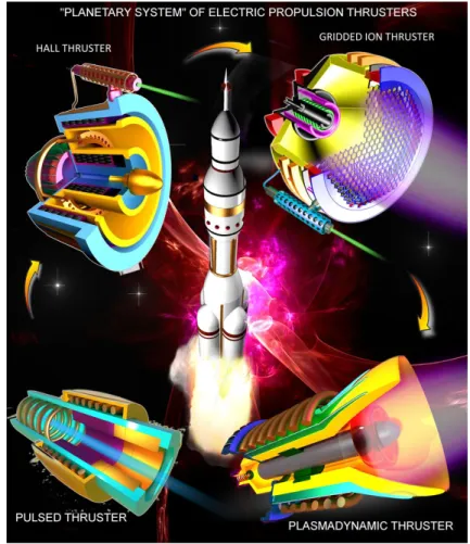
FIG. 1. A "Planetary system of electric propulsion thrusters”—four main types of electric propulsion systems currently tested and used on
small satellites and Cubesats (credit: Appl. Phys. Rev. 2018, the Authors).
FIG. 2. Why do we need to adjust the exhaust velocity? In order to obtain the maximum efficiency for the most typical case of orbital velocity,
the thruster should be able to provide 8 to 12 km/s. This is unachievable for chemical thrusters but quite trivial for any plasma-based system. Moreover, when the exhaust velocity Ve exceeds V, the energy efficiency drops off much weaker than in the case of Ve that is too low. Indeed, when Ve = V/2, the efficiency is 0.8, while for the case of Ve = 3/2V, the efficiency is 0.9.
Second, service life of the existing plasma thrusters is still not sufficient, due to very strong heat, radiation, and other
effects in the energy-loaded plasma thrust systems. Finally, plasma cathode systems still remain a critical point that
significantly limits the total efficiency and reliability of the whole space thrust systems. In this Perspective, we briefly
outline the most recent success in the plasma-based space propulsion systems, and present our view on further trends,
possibilities and challenges facing these plasma systems.
In this Perspective article, we will first briefly characterize the major and most advanced types of plasma- and electric
discharge-based space propulsion platforms, show their level of development and challenges they are facing, and
then set the ways for the future development of this field in the Perspectives section. Specifically, we will characterize
the two main groups of thrusters, i.e. the electrostatic and electromagnetic systems, as well as cathodes which play
an exceptionally important role in many various types of thrusters, such as Hall-type and gridded ion systems.
More-over, we will discuss two aspects of prime importance, namely problems and challenges linked to miniaturization of
various electric propulsion systems (
Figure 1), and advantages and opportunities provided by the application of novel
materials in this field. Finally, in a short outlook, we will set the longer-term goals and directions for this exciting
field. We aim our Perspective article at the most general physics audience and students that need to get a
compre-hensive view of the present-day state of the art in the plasma propulsion as a whole, and see the clear opportunities,
challenges and problems to be solved in the nearest future. For the more specialized expert audience, we will provide
an extended (about 190 publications) list of the most recent specialized textbooks and papers.
II. SURVEY AND PERSPECTIVES: WHERE WE ARE WITH PLASMA PROPULSION?
First of all, why plasma propulsion? Newton’s third law of motion postulates that in order to generate thrust in space,
an object must expel mass to gain accelerated, with the force expressed as F = m×V
ex, where V
exis the velocity with
which mass is expelled relative to the object and m is the rate at which mass is consumed to produce the force (kg×s
– 1). Within the bounds of classical physics, we do not consider systems that violate the law of momentum conservation.
Examples of these systems include the so-called electromagnetic propulsion, where electromagnetic forces are used
within a closed cavity. At present, there are three typical modes of space propulsion. Used to deliver assets from
Earth to space, chemical rockets are characterized by much greater thrust-to-mass ratio η reaching 2,000 N×kg
–1;
however, the exhaust velocity of these systems is comparatively low, at V
ex= 5,000 m×s
–1even for the most efficient
fuels. In contrast, systems that use electric propulsion have greater exhaust velocity approaching 10
5m×s
–1yet can
only produce low level of thrust. In these systems, ions are accelerated using electric fields, and there are no physical
limitations to hinder further improvements in the value of V
ex(
Figure 2).
In contrast to thermodynamic (chemical) rocket engines which come in just a few modifications, plasma propulsion
thrusters are represented by a quite large, diversified family which could be subdivided into the two major classes,
namely the electrostatic thrusters (
Figure 3) that use a DC potential to accelerate ions, and electrodynamic thrusters
that utilize ponderomotive forces to accelerate plasma as a whole. In additional to these two classes, plasma cathodes
could be considered as a separate type of auxiliary but extremely important devices that are either used with
electro-static thrusters, or even could be utilized as ultra-small thrusters. Electroelectro-static thrusters always incorporate a set of at
least two (sometimes more) electrodes to create an accelerating DC electric field; the electrostatic thrusters may also
include several electrodes to create a discharge between them, or may be realized in the electrode-less configuration.
An analysis of the current state of art of the electrostatic thrusters and the advanced techniques for their numerical
analysis is presented below in the section
2A.
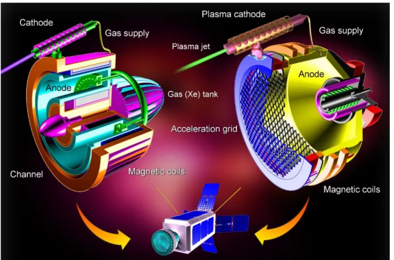
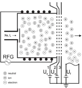
FIG. 3. Electrostatic systems: Hall (left) and gridded ion (right) thrusters, the two major candidates for powering future spacecraft. A Hall thruster24 uses a number of externally mounted magnetic coils or a single coil of a larger size surrounding the entire thruster. An internal magnetic coil may also be used. An incandescent cathode and anode are installed on the outside and inside of the acceleration channel, respectively. The acceleration channel itself can be made out of ceramic or a metal, with the latter configuration giving a thruster with anode layer. The anode is typically perforated, with the holes used to supply the propellant, e.g. Xe, as shown in the figure. Upon application of an electric potential to the cathode relative to the anode, a closed Hall current is produced within the channel, being controlled by the intersection of magnetic and electric fields. A static electric field is used to accelerate ionized propellant, whereas the magnetized electrons of the circular Hall current diffuse in the direction of the anode. As Hall thrusters are electrostatic ion accelerators, thrust they produce can be described by considering the inter-action of Hall current with the externally-applied magnetic field. An ion thruster (depicted on the right) comprises a cylindrically-shaped body housing a discharge unit, i.e. an incandescent hollow cathode, an anode, and a magnetic coil. Additional focusing magnetic coils are mounted on the outside of the body. A unit consisting of an internal and external meshes are used for extraction acceleration, respectively. An additional cathode unit is mounted on the outside of the acceleration channel, and is used to pro-duce an electron flux to neutralize the ion exhaust as it exits the channel in order to prevent charge accumulation on the spacecraft. The propellant gas such as Xe is delivered into the hollow cathode, at which point it undergoes ionization in the magnetized discharge. The internal mesh is then used to extract the ion flux, which is then accelerated by the second mesh. This results in the ion flux exiting the thruster at high velocity.
FIG. 4. Electrodynamic space thruster systems. (a) Schematic diagram of the Helicon Electrodeless Advanced Thruster (HEAT).
Adapted from Ref. [25]. (b) Magnetoplasmadynamic (MPD) thruster. (c) Pulsed plasma thruster. (d) Conceptual Rotamak-type design of a space thruster.
There are a number of electrodynamic space thruster configurations that are currently being developed (Figure 4). A typical
engine of this type operates by first ionizing the propellant, and then accelerating the ionized species along the channel. A power source on board of spacecraft is used to generate the electric and magnetic fields used for generation, control of movement and acceleration of changes particles. Once ionized, the particles can be moved along the acceleration channel by the Lorentz force, and expelled out. This force is the result of the current of the flowing plasma interacting with the externally applied magnetic field; the magnetic field may also be induced by the plasma’s current. Notable examples of such devices include the actively researched helicon plasma thruster (HPT, Figure 4a), magnetoplasmadynamic (MPD) thruster (Figure 4b), and pulsing thruster
(Figure 4c). Other examples include the Helicon Electrodeless Advanced Thruster (HEAT), which uses helicon plasma with
high density; the plasma is produced using an RF antenna, with rotating magnetic field (RMF) coils operated in the open magnetic field configuration of the divergent field used for acceleration of plasma.26,27 The rotating magnetic field induces an azimuthal current 𝒋𝒋𝜃𝜃; and the externally applied static radial magnetic field 𝑩𝑩𝑟𝑟 results in the generation of an axial Lorentz force 𝒇𝒇𝑧𝑧. If
successfully realized, the HEAT-type thrusters will be the next step in propulsion technology. At present, however, the prototype devices typically suffer from low efficiency of approximately 10-20%. More details about the characteristics of these devices are presented in the section 2B.
A. Electrostatic systems – challenges and opportunities
Hall thrusters and variants.
Electrostatic thrusters used for space propulsion of satellites and interplanetary spacecraft include two major types, namely Hall thrusters and gridded ion engines as shown in Figure 3. Ion engines deliver a high exhaust velocity,but the thrust is limited due to space charge effects. Hall thrusters offer a larger thrust-to-power ratio with specific impulses above 1000 s.18,82 In Hall thrusters, a DC plasma discharge is created inside an opened annular dielectric cavity, termed the channel, between an anode placed at the back and an external cathode. Magnetizing coils or permanent magnets wrapped around the channel produce a transverse magnetic field that confines the electrons without altering ion trajectories. The cathode gener-ates energetic electrons needed both for maintaining the discharge and for plume neutralization. The propellant gas, typically xenon for the present HT generation, is supplied in the channel through either a perforated anode, as illustrated in Figure 3, or
a dedicated injection system decouple from the anode. The cathode-to-anode potential drop is abrupt and located near the channel exit plane, a region where the electron resistivity is high due to the high magnetic field magnitude. The axial electric field combines with the radial magnetic field to generate a closed electron drift in the azimuthal direction, the so-called Hall current, which efficiently ionizes the propellant gas. Ions are subsequently accelerated outside the channel by the static electric field. Hall thrusters are thus essentially electrostatic ion accelerators.18,82 Hall thrusters have been operated with xenon and krypton as propellant in a very broad range of input power from 10 W up to 100 kW. Current state-of-the-art thrusters generate a thrust level between 1 mN and 5 N while the specific impulse stays between 1000 s and 2500 s, which is well above the maximum value chemical engine offer. Figure 5 shows an example of recently developed low-power Hall thruster suited for micro-satellite
maneuvers.46 This thruster produces 8 mN at 150 W with an anode efficiency above 30 %. Figure 6 shows the evolution of the thrust and the specific impulse with the input power for several small Hall thrusters. The general trend seen in Figure 6 is the decrease of the performance metrics when the power, i.e. the size, goes down. The anode efficiency follows the same tendency.49 This fact brings to light the difficulty in developing efficient miniature Hall thrusters.
Hall thrusters demonstrate high thrust-to-power ratios and high efficiencies over a broad power range, which make them very good candidates for various applications that encompass small and large satellites as well as Earth orbit missions and inter-planetary missions. For example, Hall thrusters are the prime candidates for the upcoming Mars colonization missions, as reported recently by NASA.28,29
Numerous works are presently aiming at improving performances and capabilities of Hall thrusters. Not only the overall effi-ciency and the thrust level are of relevance but many studies are in addition focusing on lifetime extension, operational enve-lope widening, dual-mode (high versus low specific impulse) functioning and system simplification.
The development of the Hall thruster configuration termed “magnetic shielding” has led to a drastic improvement in thruster lifetime range by decreasing the radial ion kinetic energy in the acceleration region.18,30
, 31, 32,
-33,
34,43,49 Gain in operational lifetime has been noticed in a very broad range of power, with a slight decrease in efficiency at very low power. In addition, magnetically shielded thrusters can operate with conducting walls,35,36,37,49 which opens the way to new architectures and new possibilities. Likewise, the wall-less configuration may potentially provide a means for reducing the wear of the Hall thruster assembly along with proposing a simplified design, hence a reduced cost.38
, 39,
-40, 41,
42
Sophisticated magnetic field topologies and multi-stage configurations are possible approaches under investigation for the next generation of devices, see Figure 7.43 A two- stage Hall thruster with a helicon pre-ionization stage has been proposed to enhance the ionization degree therefore allowing operation at high discharge voltages. Basically the helicon stage was placed behind the channel as shown in Figure 7a. Although addition of radiofrequency power allowed to slightly increase the thrust, the global
efficiency and the thrust-to-power drastically decreased44. Similar results were obtained with a RF antenna wrapped around a Hall thruster channel.45 A Hall thruster with two magnetic field peaks inside the channel and an intermediate electrode placed in the region of low field magnitude, the so-called double stage HT, see Figure 7b, allowed to better separate the ionization and
acceleration regions, which is necessary to enable dual-mode operation.51 A similar technique has been proposed recently with permanent magnets and an electrode located in a zero field zone near the exit plane, see Figure 7c. Although simple, the
two-peak approach has not demonstrated a large increase in the operation envelope50 whereas the system is more complex and heavier than a conventional one. An innovative design named ID-HALL for Inductive Double stage HALL thruster has recently been introduced to efficiently guide ions produced in the first stage into the acceleration zone.11 The ID-HALL architecture is depicted in Figure 7d. The ionization stage is a RF inductively coupled discharge of which the antenna is placed inside the inner part of
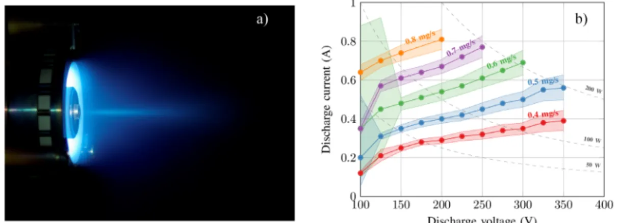
FIG. 5. 100 W class permanent magnet Hall thruster ISCT100 developed in Orléans, France. a) Photograph of the. ISCT100
firing with xenon at 100 W input power in the NExET vacuum chamber. A well collimated plasma jet is observed. b) Discharge current versus applied voltage plot. A low level of oscillation is achieved as shaded areas cover 90% of the discharge current oscillations.. Reprinted with permission from IEEE Trans. Plasma Sci. 46, 330-337 (2018)46. Copyright 2018, IEEE.
the thruster. Magnets combined with a specific magnetic circuit create a magnetic barrier at the channel exit plane, a B-field free region where the plasma is created and a cusp-like structure to limit losses at walls. ID-HALL is optimized to generate ions in the vicinity of the acceleration region. Preliminary experiments show efficient operation of the inductively-coupled plasma source with a large plasma density upstream the channel and extraction of an ion current when the device operates in a two-stage configuration with a DC voltage applied between the anode and the external cathode.11
A promising and effective approach to reach high-power operation and large thrust generation is the nested-channel Hall thruster.47,48 The principle is to combine HTs of various sizes and power levels to form a multichannel thruster, as can be seen in FIG. 8. Nesting discharge channels reduces the thruster mass and size of a high-power system. Additionally, the nested channel configuration broadens the operating envelope and facilitates throttling through the selection of available channels. To date, the nested channel technology has been successfully tested with two and three channels and it yields thrusters able to operate at over 100 kW of power. Currently a two-channel magnetically shielded thruster is under development to demonstrate life-prolonging technologies can be successfully applied to high-power devices. This work is of prime importance as long-life high power Hall thrusters would be a cost-effective technology for near- Earth and deep space applications.
FIG. 6. Thrust and specific impulse against input power for
several small Hall thrusters. The thrust, the Isp and the anode efficiency decrease when the power decreases49. The thrust-to-power ratio however stays relatively constant around 65 mN/kW.
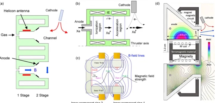
FIG. 7. What are the ways to further improve Hall thrusters and increase their performance metrics? Several conceptual designs have
been recently proposed. (a) Double stage Hall thruster with a helicon ionization stage. Reprinted with permission from Phys. Plasmas
25, 093503(2018).11 (b) Schematic view of the double-stage Hall effect thruster with an intermediate electrode (IE) and a two magnetic field peak configuration. Reprinted with permission from Eur. Phys. J. D 71, 192 (2017).50 (c) Drawing of a two magnetic peak Hall thruster using permanent magnets instead of coils. Reprinted with permission from Eur. Phys. J. D 71, 192 (2017).51 (d) The ID-Hall Double-Stage Hall Thruster. The inner cylinder and a RF antenna used to generate an inductively coupled discharge close to the accel-eration channel. Contour plots represent the magnetic field intensity distribution (bottom) along with magnetic field lines and (top) the ideal spatial distribution of the power absorbed per electron. Reprinted with permission from Phys. Plasmas 25, 093503(2018).11
FIG. 8: 10 kW class X2 two-channel nested Hall thruster with its centered-mounted
cathode firing with xenon at full power in dual channel configuration. Image courtesy of Ray Liang, reproduced with permission.
Ion engines. In an electron bombardment ion engine, a cylindrically-shaped body houses a discharge unit. The unit consists an
incandescent hollow cathode, an anode, and an internally-mounted magnetic coil. Externally-mounted magnetic coils are used for focusing. An acceleration mesh unit contains an internal and external meshes used for extraction and acceleration, respec-tively. An additional cathode is mounted on the outer body of the thruster (Figures 3 and 9). The propellant, most often Xe, is
delivered to the hollow cathode, where ionization takes place within a magnetized discharge. Once it is extracted and accelerated by the respective meshes, the ion flux is expelled from the thruster at high speed. The role of the electron flux produced by the externally-mounted cathode is to counteract the electric charging by the ion flux with the aim to prevent charge accumulation on the spacecraft. It is worth mentioning that in both types of thrusters discussed so far, the plasma is generated and sustained by electron-neutral collisions. Evidently, plasma can be sustained using other methods, for examples by using radiofrequency- and microwave-driven ionization, with both methods employed in electric propulsion.
FIG. 9. Schematics of the radio frequency ion thruster including the
elec-tric interconnection of extraction grids and thermionic neutralizer. Us is the screen grid (1) and Ua the acceleration grid (2) voltage, respectively. The deceleration grid is on ground potential. Electrons for neutralization are provides by a tungsten filament (Uf is filament heating voltage). Reprinted with permission from Eur. Phys. J. D 72, 1-7 (2018).52
Along with many advantages of gridded ion thrusters such as very high specific impulse, some drawbacks can be pointed out. These include lower ionization efficiencies as compared to that of Hall thrusters. To overcome this, the radiofrequency ionization stages also could be specified as a promising technology to bring the gridded ion thrusters to the orbit of commercial exploitation. Moreover, the use of iodine instead of widely used Xenon for gridded ion thrusters may be very promising to reduce the cost of the long space flights; however, iodine is a corrosive substance. The readers may refer to numerous recent publications to review the recent progress with various types of the modern gridded ion thrusters.53
, 54,
-55, 56, 57,
58
Gridded ion thrusters, due to very high intrinsic specific impulse and other advantages, will be among the most intensely re-searched space thrust platforms; the use of multi-staged radio-frequency driven thrusters and alternative propellants such as iodine may be pointed out as the most promising directions for further studies.52,59
B. Electrodynamic systems
There are a number of benefits to using magnetoplasmadynamic (MPD) thrusters. These include attractive thrust density ap-proaching 100 mN×cm-2, high power (~MW), lower voltage, a simple device design and the possibility of using several propel-lants, including gases and metallic solids. This makes this form of propulsion highly promising for long-distance missions, such as for deep space exploration, due a favorable combination of high efficiency (up to 70%), and thrust and impulse reaching tens of newtons and 104 s, respectively. In this device, the interaction between the current flowing through the plasma and a magnetic field produces the Lorentz force needed for plasma acceleration. The magnetic field can be generated using externally mounted coils, or arise from the plasma’s own current. Unlike pulsed plasma thrusters (PPTs) that are able to generate high specific impulse at low-power, MPD thrusters are not ideal for the use in small satellites. Indeed, the former are well suited for attitude and orientation control, and low-thrust maneuvers by small space assets. PPTs that use ablation of solid propellants have the added benefit of design simplicity and high specific impulse.60,61 These devices take advantage of the inherent properties of plasmas to generate thrust and gain considerably high velocity with very low fuel consumption.62
Helicon plasma thrusters is one of the most promising systems that is currently undergoing active exploration. Helicon
plasma sources (Figure 10) generate plasmas by using radio frequency radiation. They generate plasmas of high density (∼1013 cm-3) and can sustain a wide range of external operating parameters. For this reason, many different helicon sources of different geometrical scales have been designed and their ability to control plasmas described.63,64,65 They feature very complex phys-ics66
, 67,-68,69, but hold high promise for space thruster applications70. We expect the explosive evolution of high-density helicon
plasma sources, which have many advantages compared to other sources from the viewpoints of easy handling of high-density plasmas over a wide range of external parameters. Various ideas developed thus far should be converted into practical devices for future innovative technologies in diverse fields as well as for contribution to basic fields of science.71
, 72,
-73,
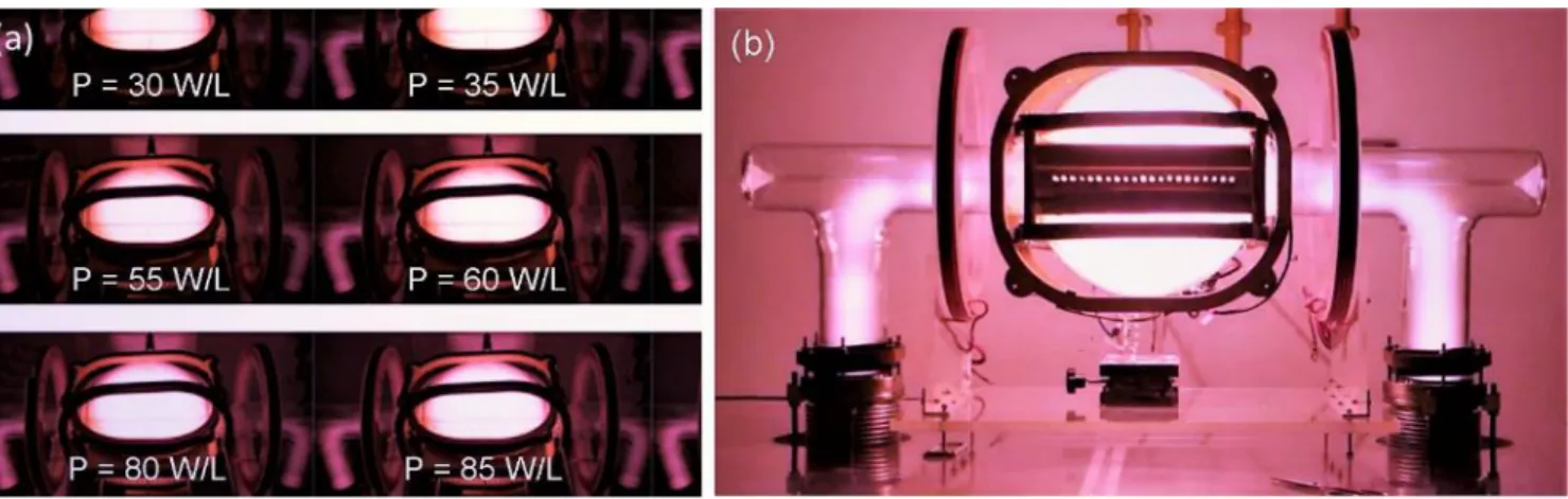
FIG. 10. (a,b) Schematics of the Helicon plasma systems operating in the rotating magnetic field (RMF) mode, which has been
originally utilized in the nuclear fusion field (a), and in the m = 0 half-cycle acceleration mode (here m is an azimuthal mode number). The basic mechanism is to induce an azimuthal current jθ in the divergent magnetic field to produce the jθ×Br axial Lorentz force, where Br is the static radial magnetic field. Reprinted with permission from Plasma Phys. Control. Fusion 61, 014017 (2019). Copyright 2019, IOP. (c) Helicon plasma thruster firing in the 500-1000 W radio-frequency power range, at 13.56 MHz with Xenon in the vacuum chamber. Importantly, plasma flow could be efficiently controlled in the helicon thrust-ers.73 Reprinted with permission from Vacuum 149, 69 (2018). Copyright 2018, Elsevier.
FIG. 11. The experimental results when thrusters are powered by (a) one RF power supply; (b) two RF power supplies. (c-e)
FIG. 12. Schematics of the proposed concept of
micro-cathode arc thruster with high thrust (μ-CAT-HT). Such a thruster can feature a thrust-to-power ratio of about 20 μN/W, with the efficiency of up to 15%. Plasma is also accelerated by the Lorentz forces.
Before they can take their place in the suit of widely used propulsion devices, helicon plasma thrusters need to resolve a number of challenges. These include the current-related erosion of the cathode, comparatively low rate of propellant ionization, instability associated with the use of high-power plasmas, to name but a few. These challenges hinder the advancement of the currently available magnetoplasmadynamic thrusters. The development of a spherical plasma source has provided a pathway for the realization of a gradually expanded Rotamak (GER, Figure 11) system as a potential candidate for space propulsion. With
further development, the GER-type devices could enable the production of azimuthal plasma currents. The latter could be used to drive indiscriminate acceleration of species within the plasma, e.g. electrons, ions and neutral species, through an axial body force.
Other advantages of GER-type thrusters include the elimination of the requirement for pre-ionization stages, as well as the need for neutralizers and high voltage extraction and acceleration grids typically required for the efficient performance of con-ventional ion and Hall thrusters. Of most significance is the possibility of scaling operational power regimes, reducing plasma-wall interactions, and obviating the need for moving components. These features will make GERs as a thruster of choice for long haul missions in LEO and geostationary orbit, and for deep space exploration. Of the available options, a Rotamak device de-veloped by Flinders University in the 1960s presents an attractive alternative. Rotamak was originally dede-veloped as a more compact alternative to a tokamak, since is lacks an inner column, which is also more efficient due to higher fuel density.75
Rotamak uses a spherical discharge vessel. The external sources are configured so as to enable a “field reversed configuration” as well as other current drive schemes.76 The gradually expanded Rotamak (GER) device based on a Rotamak was developed by the Space and Propulsion Centre (SPC) at the National Institute of Education, Nanyang Technological University, Singapore. Preliminary studies on its use for space propulsion are encouraging, confirming its potential for the development into a pure electromagnetic thruster that could sustain high density, non-inductive plasmas. Specifically, the device produced dense plasmas in a spherical vessel. A pair of parallel RF coils can be used to sustain these plasmas. These coils are located outside of the confinement vessel. An additional pair of coils is located orthogonally to the former RF coils. Their role is to provide a poloidal magnetic field, which is generated by the use of a DC pulse. The poloidal field leads to plasma confinement and densification in the middle of the discharge vessel. It is possible to modify device configuration and geometry to realize a fully electromagnetic thruster, where acceleration and thus the thrust is sustained by an axial body force in the absence of neutralizes and grids typical of conventional electric propulsors. Importantly, larger thrust values per unit propellant could be generated, a requirement for longer haul missions.
Arc thrusters, pulsed and ablative systems are examples of thrust systems that share similar physical mechanisms and very
small size (up to several mm), which makes them well suited for application on small satellites.77,78,79 Micro-cathode arc
thrusters (μ-CAT, Figure 12) are also actively investigated, with examples including microthrusters employing a Ring
Elec-trode, a Coaxial ElecElec-trode, and an Alternating Electrode developed by the George Washington University’s Micropropulsion and Nanotechnology Laboratory (MpNL) since 2009. These configurations differ with respect to their performance and opera-tional characteristics, namely thrust and working life. On average, μ-CAT available at present feature a thrust-to-power ratio and efficiency of approximately 20 μN/W and 15%, respectively. A major limitation of this device is that ~ 10% of the discharge current contributes to the ion current, and thus to thrust, with ~ 90% of the discharge current conducted by electrons spent on anode heating.8,80,81
Overall, at the present stage of development and understanding of the basic plasma physic mechanisms of the electrodynamic space thrusters, we can see the following opportunities and advantages presented by electrodynamic plasma thrusters when compared to electrostatic and electrothermal propulsion devices:
Ability to produce considerable thrust densities since particle acceleration is not restricted by Hall parameters
or grid electrical screening;
Absence of the requirement for a neutralizer since the ponderomotive force is capable of accelerating all plasma
species along the direction of the plume;
Ability to switch the thruster between optimum specific impulse and greater thrust while maintaining constant
power enabled by the inherent multi-staged nature of the electrodeless plasma thruster, which allows for
inde-pendent optimization;
Minimal electrode degradation and absence of plasma contamination for the helicon and Rotamak devices
en-abled by the use of a combination of non-uniform high frequency field and a static magnetic field to generate
the ponderomotive force, which means that the plasma does not come into direct contact with electrodes and no
grids are used for species acceleration and extraction.
2C. Hollow cathode systems for space electric propulsion thrusters
Hollow cathodes are used in Hall effect and ion thrusters to provide electrons for the propellant ionization and the neutralization of the ion beam. The cathode affects the overall performance and lifetime of the thruster unit. The cathode propellant consump-tion, along with a possible additional power required to ensure its operaconsump-tion, has a direct impact on the thrust efficiency. The cathode position is an important aspect to be studied, since it affects the thruster performance characteristics and the cathode erosion. As such, important goals for the cathode development are a reduction of propellant consumption, an improvement of the thermal design to lower the heat losses from the hot parts, and an increase of the cathode service life. Below we briefly discuss the recent advances and future perspectives in hollow cathodes, starting from an outline of the basic physical phenomena involved in the operation of hollow plasma cathodes, discuss some achievements in the modeling and simulation of plasma cathodes, and describe the low and high current hollow cathodes, respectively.
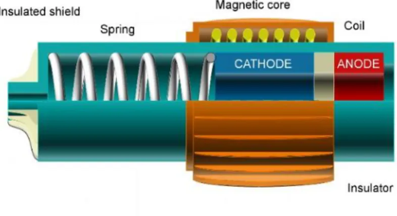
Physical Phenomena in Cathodes. The general schematic of a traditional hollow cathode is shown in Figure 13.82 The cathode uses a refractory metal tube to support the thermionic insert (or emitter). The insert is held in place by a pusher and spring arrangement, and pushed against a refractory metal end plate with a chamfered orifice. Historically, two type of inserts have been used in hollow cathodes: barium-oxide impregnated tungsten dispenser inserts, and lanthanum hexaboride (LaB6).83 Barium-oxide inserts have a low work function (about 2.1 eV), but a maximum continuous current density of 20 A/cm2 at a temperature of about 1200 ˚C. LaB6 is a well-known thermionic insert used in low power flight Hall thrusters from Russia since the 1970’s.84 LaB6 has a higher work function (2.67 eV) than BaO dispenser cathodes, and therefore operates at temperature of just over 1600˚C to produce about 10 A/cm2 emission current density. LaB6 also has low evaporation rates and is insensitive to poisoning from impurities in the propellant gas.
A heater can be included in the cathode assembly, to warm the insert up to thermionic emission temperatures prior to ignition. High current cathodes feature a high temperature coaxial sheathed heater, coiled around the cathode to provide sufficient heating to start the discharge. Alternative heater solutions in use or under development are described in Sections 0 and 0. A heat shield consisting of layers of thin refractory metal foil are used around the heater coil to improve the heating efficiency. This arrange-ment is surrounded by an isolated “keeper” electrode that is used to help ignite the discharge and also to protect the orifice plate from energetic ion bombardment from the cathode plume. The keeper material is chosen to minimize sputtering, and graphite keepers are commonly used in present high current cathodes.
FIG. 13. A typical configuration of a hollow cathode showing its main components. The in-sets made of a material with ow work function ensures efficient emission of electrons. A heater is used to maintain high temperature needed for electron emission, and also reduces the total heat flux from an outer surface of the cathode (an additional thermal screen can also be used to enhance the efficiency). Reprinted with per-mission from Nat. Commun. 9, 879 (2018).
Copyright 2018, Authors.
In recent years, extensive theoretical research of a variety of hollow cathode phenomena has been conducted. The research focused mainly on several specific physical processes: the neutral flow dynamics in the cathode interior,85,86 electron transport and anomalous resistivity,87
, 88, 89,
-90, 91,
92 spot and plume mode physics.93,94 Particular attention was given to the theoretical and experi-mental investigation of cathode instabilities, both in the cathode interior and cathode plume region.95,96,97 The ultimate goal of the aforementioned studies is to broaden the understanding of cathode-related physics, as well as to formulate relations between the various cathode parameters; relations that would enable the design of more power- and propellant-efficient cathodes. Several specific goals can be accomplished in the near future, thanks to the currently confronted theoretical challenges mentioned above. Once accomplished, these goals would advance the cathode effectiveness and the ability to adequately design and test hollow cathodes.
Firstly, the understanding of cathode plume physics would enable proper testing of cathodes in diode mode configurations (against an anode structure instead of with a thruster). Further understanding of cathode plume physics can dictate the required experimental setup, i.e. anode geometry, cathode-anode distance, additional peripheral mass flow rate, background pressure etc. Secondly, an improved theoretical understanding of cathode/keeper orifice physics would lead to possible mitigation of orifice wear that would potentially extend cathode life and enable operation at a wide range of discharge currents, specifically high current levels.
Thirdly, theoretical understanding of the interaction between the plasma flow and the interior cathode structure would allow for the development of novel cathode configurations. For example, the physics of “open-end emitter, orificed keeper” configurations, commonly used in heaterless hollow cathodes, would reveal the optimal geometry for efficient emitter heating while minimizing ion density and energy in the vicinity of the keeper orifice, thus reducing orifice erosion.
Lastly, it is but natural that further theoretical research of cathode-related physics would unfold a myriad of new possibilities, currently unconceived, ultimately leading to new and improved cathode configurations, designs and cathode operation schemes.
Low Current Hollow Cathodes. The Low current cathodes find their principal use in nano- and micro-satellites deployed for
varied purposes: scientific research, Earth Observation, astronomy, as well as technological, educational, and military applica-tions. Advances in microelectronics and miniaturized systems established a breeding ground to actualize the efforts devoted in recent years to lower the operating power of electric thrusters, with the goal of addressing the micro/mini propulsion market.8 The related activities aim at the development of propulsion subsystems characterized by low cost, low power consumption, low mass, high thrust controllability, and manufacturing capability. The latter aspect is particularly important for constellations of satellites, which will mainly use electric propulsion for end-of-life de-orbiting. Another aspect under continuous investigation is the possibility to operate the electric thrusters with alternative propellants; in particular, iodine is a valid candidate to be used in low-power applications.98
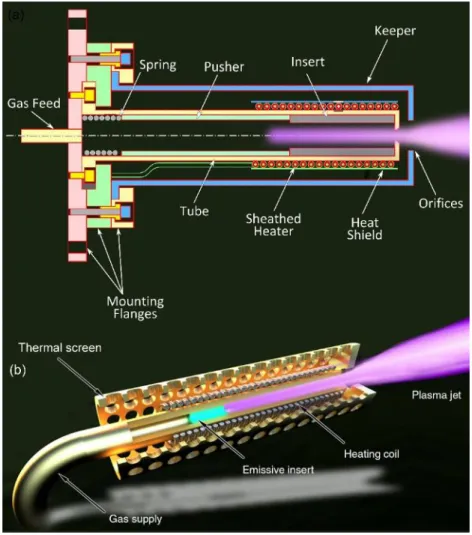
The traditional hollow cathode architecture (Figure 14) has been adopted by various research institutions and industries,99
, 100, 101,
-102, 103,
104 based on lanthanum hexaboride or barium-oxide tungsten impregnated inserts. Another promising insert material is the electride C12A7e-, which is currently under study for the low current class of hollow cathodes.105,106. The traditional hollow cathode design presents a single point of failure, namely the heater. The heater is generally made of a refractory wire (tantalum, or tungsten alloy), electrically insulated from the cathode tube by means of ceramic components. Alternatively, a potted heater is included in the cathode assembly. The mineral insulated cables as used to heat the high-current hollow cathodes (Section 0) could be also used for the low current cathodes, provided the cable dimensions will be efficiently scaled down to fit the smaller geometrical envelope.
To overcome the reliability and manufacturing issues tied to the heater, the Heaterless Hollow Cathodes (HHCs) architecture was devised not to require external heating to bring the electron insert to its operation temperature.82 Instead of using external heating, as with conventional cathodes,82 HHCs are heated via plasma heating. When the electron insert is sufficiently hot, the HHC may function as any other conventional hollow cathode, under steady state conditions. HHCs are suitable primarily for low-current hollow cathodes, since the heaterless ignition may induce a high thermal stress on the insert when reaching relatively high discharge current levels.107,108
In recent years, HHCs have seen an increased interest, specifically for low current hollow cathodes.109,110,111,112,113,114 The quick ignition time, low power demand during the ignition phase, and the potentially longer lifetime have made these cathodes attrac-tive options for low power ion and Hall thrusters. To date, the HHC technology has overcome two technological challenges: the ignition voltage is reduced to merely several hundred volts,104 and the transition to operational temperature of the insert is with minimal damage to the cathode, thus allowing for thousands of ignitions.114 Further, it was shown that low-power HHCs can operate adequately with different insert materials such as the electride C12A7e-,110,111 BaO-impregnated tungsten,113,114,115 and LaB6.112,113
Nevertheless, the current HHC technology development still needs to overcome two leading challenges:
1) Cathode Conditioning: after exposure to ambient air the insert must be conditioned, that is gradually heated to emit
impurities.116 However, since HHCs are heated via plasma formation in the cathode cavity, a dedicated rigorous and methodological research is required to define the appropriate cathode conditioning schemes. The research should include the correlation between keeper (or anode) current, insert temperatures, and the required time to achieve the cathode con-ditioning for each current level;
2) Breakdown voltage sensitivity to temperature: it was shown that in cylindrical geometry the breakdown voltage
in-creases with decreasing temperatures.117 An apparatus that enables the reduction of HHC temperatures prior to ignition was proposed and designed.118 However, test results of the sensitivity of cathode ignition to cathode temperature were yet to be published. To properly qualify an HHC, for in-space missions, its sensitivity to low temperatures, primarily the required ignition voltage, should be studied experimentally.
New frontiers of the low current cathode development include new designs, new concepts, and new advanced materials. Ul-trananoporous inserts are under study to reach a longer cathode lifetime, through a larger surface area per volume unit, also increasing the efficiency due to the smaller required heated volume.119 Carbon nanotubes possess a potential for cold, propellant-free cathodes, whereas nanoscale metamaterials capable of reversal heat transmission could help to reduce heat losses.120
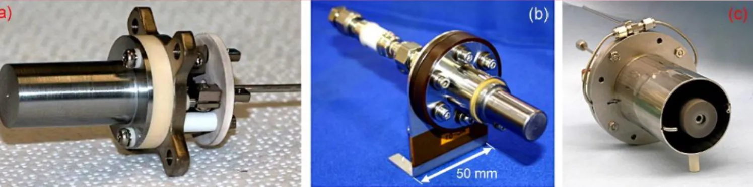
FIG. 14. (a) SITAEL’s HC1 cathode, and (b) Rafael’s RHHC cathode. (c) The X3 cathode assembly with external gas injectors required for
operation over 200 A of discharge current. Reprinted with permission from J. Prop. & Power 30, 1155 (2013). Copyright 2013, AIAA.
Concerning the large production of hollow cathodes, advanced manufacturing techniques (e.g. additive manufacturing) could play an important role, with simplification of the cathode design and manufacturing flow for the new, ambitious satellite con-stellations.121
High Current Hollow Cathodes. Hollow cathode used in present flight ion thrusters and Hall thrusters are capable of producing
discharge currents of up to about 25 A. The next generation of Hall thrusters planned to operate in the 5 to 20 kW range require discharge currents of less than 50 A. Development of higher current hollow cathodes was first performed in the 1970’s,122 pri-marily for non-thruster applications such as ion sources for neutral beam injection heating in fusion experiments. These cathodes routinely operated from 50 to over 500 A of discharge current, which we will consider as “high current” hollow cathodes. There are five major issues that dominate the design of high current hollow cathodes:
1. Insert emission current density and evaporation; 2. Plasma contact area inside the insert;
3. Orifice plate design; 4. Heater capability;
5. Energetic ion and electrode sputtering suppression.
Comprehensive modeling and numerical simulation of hollow cathodes, required to provide design guidelines or explanations for the performance and life of high current hollow cathodes, as described in Section III. MODELING AND SIMULATION. At temperatures over 1100 ˚C, BaO dispenser cathodes have significant evaporation rates and tend to form tungstates, both of which limit their life in high current applications where power deposition from cathode self-heating is significant. A preferable insert material for high current hollow cathodes is LaB6: the higher temperature operation and the higher emissivity of LaB6 (compared to BaO-W inserts) means that the insert radiates effectively and overheating is not a significant issue.
Of critical importance in high current hollow cathodes is the axial plasma density profile in the insert region because the insert temperature profile depends on the plasma contact area.123 More uniform axial densities result in more uniform insert tempera-tures and evaporation rates. Also, space charge effects can limit the thermionic emission current if the plasma density becomes too low toward the upstream end of the insert. This will limit the electron emission area and how much current the insert can provide into the plasma. Operation at higher discharge current and higher gas flow rates often required by higher power thrusters tends to push the plasma downstream toward the orifice plate, further limiting the insert contact area. The only solution is to make larger diameter cathodes with larger diameter inserts, and increase the cathode orifice size to maintain the pressure in the nominal 1-Torr range required to get proper hollow cathode operation.82
The orifice plate in hollow cathodes often limits the current capability of the device. This is because the orifice size determines the current density of the extracted electrons, which affects the generation of instabilities and energetic ions in the cathode plume. The orifice size also determines the pressure inside the cathode for a given gas flow, which as described above impacts the plasma contact area, the required insert temperature to produce the discharge current, and therefore the insert life. Finally, orifice plate heating is significant in high current hollow cathodes,124 and larger orifice plates are required to radiate the power away. High current hollow cathodes have large radiation and conduction areas, and so require high power (200-400 W), high temper-ature (>1400 ˚C) coaxial sheathed heaters or filament heaters wound in an insulating mandrel around the cathode tube. Conven-tional BaO-W dispenser hollow cathodes use coaxial sheathed tantalum heaters with a MgO powdered insulation capable of nominally up to about 100 W of power. High current LaB6 hollow cathodes typically use a tantalum sheathed-heater that incor-porates high-temperature alumina-powder insulation.124 Alternative heaters based on refractory metal filaments in ceramic man-drels or thin film heaters on ceramic substrates are in development for this application.
Operation of hollow cathodes at high discharge currents tends to generate ionization instabilities or current-driven turbulent ion acoustic instabilities in the near cathode plume.125 These produce energetic ion generation that erode the cathode and keeper orifice plate and limit the cathode life. Proper selection of the cathode orifice size and the gas flow rate at a given discharge current has been used in lower current hollow cathodes to avoid these modes.126 Unfortunately, this is not usually sufficient in high current hollow cathodes and extraordinary measures are required to avoid or damp these instabilities. The only successful method to date of damping both the ionization and ion acoustic instabilities has been the injection of extra neutral gas in the near-cathode plume.127 It is undesirable to simply increase the cathode flow rate to achieve this damping because (as described above) the resulting higher pressure inside pushes the plasma in the insert downstream toward the orifice plate and reduces the plasma contact area with the insert (affecting life). However, extra gas on the same order as the cathode flow rate can be injected external to the cathode or into the plume through the cathode to keeper gap to damp the instabilities. Gas injection external to the cathode orifice plate has been used in the 2.1-cm-dia. X3 cathode for all operation from 200 A to 330 A of discharge current.
Figure 14c shows a photograph of the external gas injectors on the X3 cathode assembly.
High current hollow cathodes that are capable of producing 50 to 300 A of discharge current are available now for development as flight cathodes. Achieving higher current with long life will require larger diameter inserts to provide more area for electron emission, larger insert IDs for sufficient penetration of the plasma density upstream for complete contact area with the insert, thicker inserts for longer life, larger cathode orifice plates to radiate the power away, higher power heater designs, and optimized external gas injection schemes. While LaB6 provides high current operation with long life (many tens’s of khours), robustness against poisoning, and the ability to handle the high-power heating at high discharge currents, new thermionic cathodes with low work functions and evaporation rates are desirable. Modeling of the cathode operation, thermal performance, and the plasma discharge instabilities needs to be continued until fully predictive design codes are available.
III. MODELING AND SIMULATION: CHALLENGES AND FRONTIERS
A. Modeling approaches
Numerical modeling and simulations are very powerful tools that ensure strong reduction of time and resources needed to design, test, and optimize space propulsion thrusters. Moreover, modeling and numerical simulations become even more important for miniaturized plasma thrusters, since with the scale reduction, measurements become more and more difficult and invasive. In addition, with the progress made in the high-performance computer (HPC) technology, the high-fidelity of reproduction and fast execution time of numerical models are rapidly improving. As a proof of the importance of nu-merical modeling in electric propulsion community, a dedicated project named LANDMARK128 (Low temperAture
mag-NetizeD plasMA benchmaRKs) has been developed in the last two years. The project aims at: (1) providing an open forum for evaluating methods of description of plasma transport in non-fusion magnetized plasmas (eg. ion sources, HTs, mag-netrons, cusped-field thrusters, etc.); (2) defining benchmark test cases for full-kinetic, fluid and hybrid methods; (3) ad-dressing physics issues related to the questions of anomalous transport across magnetic field, instabilities, plasma-wall interactions and their influence on particle and energy transport; (4) facilitating international collaboration and enhance mutual understanding among researchers.
FIG. 15. Diagram showing one
integra-tion time step of a PIC MCC simulaintegra-tion.
B. Kinetic techniques
The full kinetic description has been often applied to HTs configurations. Since electron thermalization and isotropization rates are quite low in HTs, kinetic approaches are more suitable to represent the important deviations of electron distribution functions from Maxwellian one. Furthermore, kinetic approaches are of ab-initio type and do not require any empirical adjustable param-eter to fit the experimental current. Among the different kinetic techniques, Particle-in-Cell-Monte Carlo Collision (PIC-MCC)129model in the electrostatic approximation is the most used. It consists of a mixed Lagrangian-Eulerian (particle-mesh)
solution of the coupled Boltzmann-Poisson equations. By means of the Klimontovich-Dupree representation of distribution functions, electron and ion Boltzmann equations reduce to the solution of equations of motion for macro-particles (clouds of real particles representing small regions of the phase space). Fig. 15 illustrates the PIC-MCC typical cycle. The charge density is
deposited on a spatial mesh (whose size must be smaller than the Debye length, step 3) where the electric potential is solved (step 4) and from where the electric field is interpolated back to the macro-particle locations (step 5). After pushing the virtual particle (step 1) and before restarting the PIC cycle again, a MCC130 module (step 2) is called to process volumetric
(electron-neutral, ion-neutral and Coulomb collisions) or surface events (secondary electron emission131, ion sputtering132, etc.). PIC-MCC
is a very powerful numerical tool which allows very accurate and extremely detailed analysis of plasma and discharge parame-ters. However, there are important constraints associated with PIC-MCC methods. In the explicit version, because the electric field is supposed to be constant during one time step, the integration time step must be less than the inverse of the plasma frequency. The grid spacing must also be limited to make sure that one particle does not move over more than one grid interval during the time step. Another constraint is that the number of particles per cell of the simulation must be large enough to avoid statistical errors and numerical heating.
The most important features of HTs PIC-MCC models are:
(i) Solution of Poisson equation for the self-consistent electric field. It allows resolving the deviation from the quasi-neutrality in the plasma-wall transition regions;
(ii) Detailed description of the electron-wall interaction.133 With a high surface-to-volume ratio, plasma-wall interaction plays an important role, not only as loss but also as an active source of particle and energy terms;
(iii) Ability to reveal micro-instabilities and self-organized structures typical of E×B partly magnetized low temperature plasma devices, such as electron E×B drift,134,135 spoke,136 sheath,137 and two-stream138 instabilities. Detailed description of meth-ods, advanced numerical algorithms and high-performance computing techniques applied to PIC-MCC models be found in a recent review publication.139,140
Fig. 16 shows examples of self-organized structures detected by PIC-MCC models. In Fig. 16(a) the temporal evolution of the
azimuthal profiles of electron density is reported. It is evident the electron E×B drift instability characterized by a non-linear evolution towards longer wavelengths by inverse energy cascade. Fig. 16(b) reports the m=1 spoke instability rotating with a velocity of 6.5 km/s. Both phenomena leads to similar high-frequency electric field oscillations characterized by a wavelength of mm-scale, frequency of few MHz and amplitudes of the order of 100 V/cm that have also been experimentally observed141
FIG. 16. (a) Temporal evolution of the electron density profile along the E×B direction y in the acceleration region of HT. (b)
Evolution of the plasma density 3 mm above the anode during the spoke cycle. Reprinted with permission from [120]. Copyright 2019, IOP.
The primary challenge concerning PIC-MCC codes is being able to describe HTs through a full three-dimensional repre-sentation. This result will be possible by increasing their scalability up to 105 processors using optimized Poisson equation
solvers, implementing particle sorting techniques and taking advantage of particle domain decomposition on modern su-percomputer architecture (CPU/GPU combination).
Kinetic PIC methods are extremely powerful and convenient tools to significantly cut off the time and resources
need for optimization of plasma thrusters; further development of this technique is in a high demand.
Kinetic numerical modeling is efficient for investigating self-organized structures and micro-instabilities
typical of E×B partly magnetized low temperature plasma devices.
C. Fluid-Hybrid technique
The main difference between fluid and hybrid approaches lies in the fact that the description of ions through macroscopic equations solved to obtain density, mean velocity and energies (assuming Maxwellian distributions) is replaced by a kinetic description where the ion energy distribution is self-consistently calculated. Fluid-based models are valid when the distri-butions of particles are closed to equilibrium meaning that the pressure is high enough for charged particles to collide between them rather than with walls, as in electromagnetic engines and thermionic cathodes. In electromagnetic thrusters, fluid equations are coupled with Maxwell’s equations to self-consistently determine the induced electric and magnetic fields profiles.142,143 The complexity of electrodynamic thrusters in terms of dynamics of instabilities shows the very big
challenges that fluid modeling must tackle in the coming years.
In electrostatic thrusters, the ion energy distribution varies in time and space and corresponds to a peaked distribution far from equilibrium and those properties have to be self-consistently determined. In that way, a hybrid approach is preferably employed. In ion thrusters, the modeling efforts are mainly related to ion optics and its consequence on grid erosion. The fluid transport of electrons is most of time simplified through a Boltzmann relation with a given electron temperature that makes electrons immediately respond to electric potential variations. Poisson’s equation is solved to calculate the electric
field profile due to space charge face to grid apertures,144,145,146 Fig. 17 illustrates a comparison of the effect of charge
exchange collisions on grid erosion for an ion thruster working with xenon and krypton propellants. 3D Commercial soft-ware are now able to properly define a best design for the grid system according to the thruster operation and challenges have to be focused on basic data of ion sputtering for different grid materials.
FIG. 17. Distribution of charge exchange collision rate
and its influence on current density on the accelerator grid. (a, b) CEX collision rate of Kr and Xe ion thrust-ers, respectively; (c, d) Current density on accelerator grid of Kr and Xe ion thrusters by CEX ion impact. Reprinted with permission from M. Chen et al. Copy-right 2018 Elsevier [145].
HTs being not space-charged limited and self-induced magnetic field ignored, self-consistent electric field is deduced from the electron fluid transport assuming the quasi-neutral hypothesis. Sheath properties (including the effects of secondary electron emission and sputtering) are analytically described.147 Hybrid approaches have encountered a large success in the
HT operation description with the prediction of so-called breathing mode and transit-time oscillations, as illustrated Fig. 18.
To go further in HT fluid and hybrid modeling, a first challenge concerns the capability to propose efficient numerical schemes able to capture the effect of non-diagonal terms in the tensor of transport coefficients to be able to model a large variety of magnetic field configurations,148,149 The second and main challenge concerns the including of mechanisms
re-sponsible for anomalous transport through electron-wave interactions (high small scales and low frequency-large scales, as illustrated in Fig. 18 and its implementation via wave-interaction equations134,150,151 or analytical laws
derived from numerous experimental campaigns.152
Finally, whatever the type of electric propulsion system, the study of interactions between the plume and the satellites and the induced spacecraft charging is on first importance. Hybrid approach assuming a Boltzmann equilibrium for un-mag-netized electrons is the more often used. Three-dimensional large scale tools like the open-source SPIS software153,154 are
able to contain all the geometry satellite but actually with simplified boundary conditions for charged particle properties coming from thrusters. The coupling between refined models of electric propulsion systems and larger scale plume-inter-action tools, validated with measurements, is crucial for the electric propulsion community.
FIG. 18. (Top) 1D axial hybrid model results.
(a) Neutral density (maximum 1.6×10¹⁹ m-3), (b) Plasma density (maximum 1.6×10¹⁸ m-3). Reprinted with permission from F. Darnon et al. Copyright 1999 IEEE [155]. (Bottom) 2D (axial-radial) hybrid model results. Discharge and ion currents as a function of time showing the breathing model oscillations at a fre-quency of 20 kHz with ion transit-time oscil-lations at 200 kHz superimposed. Reprinted with permission from J. Bareilles et al. Copy-right 2004 AIP [156].
IV. NEXT STEPS
Where should the future electric and plasma propulsion technology go in the nearest future? We would like to emphasize three directions of high priority: miniaturization, uptake of the advanced and self-healing materials, and search for new device para-digms to widen the niche of possible applications for plasma space propulsion.
3.1. Miniaturization
Our built environment is in the process of overwhelming miniaturization. Handy, portable and wearable devices, multifunctional smartphones, crystal-size computers and other new-sprung inventions are now penetrating even facet of our life and revolution-izing how we deliver and consume products and services. Miniaturization of space assets is steaming ahead, bringing along obvious advantages. Most probably, miniaturization alone would likely to remain a key trend and a major driver for the advancement of future spacecraft. Miniaturization provides additional space – and the space is limited even in space! This is particularly true for near-Earth orbits where debris can be encountered more often than operational satellites. Moreover, minia-turization along with use of small and ultra-small satellites en masse means new capabilities – that’s the main point.
Miniaturization means lower cost and hence, much higher affordability and easier access to space for those who need some special functions but cannot spend millions to purchase the entire launch – example include small scientific labs, private com-panies and universities. Most importantly, small satellites could form networked distributed systems – dynamically changing, adaptive constellations for the mission-oriented, coordinated formation flights of a large number of mini-satellites that feature expressive capabilities not really available using several satellites with the total mass comparable to the net mass of the constel-lation. New opportunities offered by these interconnected networks include the widest-possible coverage of survey and infor-mation pickup; and larger, of the constellation size, observation bases with the relevant resolution and ability to collect and coherently process the information inside the constellation that open new horizons for the efficient, robust space exploration.1 And this holds true not only near the Earth. Small yet organized groups of small satellites at the Moon and Mars orbits could be quite realistic and a much cheaper alternative to large, heavy universal probes that require heavy launch vehicles to reach remote planets. Deep-space Cubesats are nearing reality.157