HAL Id: hal-03144472
https://hal.archives-ouvertes.fr/hal-03144472
Submitted on 17 Feb 2021HAL is a multi-disciplinary open access archive for the deposit and dissemination of sci-entific research documents, whether they are pub-lished or not. The documents may come from teaching and research institutions in France or abroad, or from public or private research centers.
L’archive ouverte pluridisciplinaire HAL, est destinée au dépôt et à la diffusion de documents scientifiques de niveau recherche, publiés ou non, émanant des établissements d’enseignement et de recherche français ou étrangers, des laboratoires publics ou privés.
ANALYSIS OF NUPEC TEST CASES
Sara Touhami, Vinicius Fernandes, Fernando Lopez-caballero
To cite this version:
Sara Touhami, Vinicius Fernandes, Fernando Lopez-caballero. STRUCTURE-SOIL-STRUCTURE INTERACTION ANALYSIS OF NUPEC TEST CASES. 6th ECCOMAS Thematic Conference on Computational Methods in Structural Dynamics and Earthquake Engineering, Jun 2017, Rhodes Island, Greece. �hal-03144472�
M. Papadrakakis, M. Fragiadakis (eds.) Rhodes Island, Greece, 15–17 June, 2017
STRUCTURE-SOIL-STRUCTURE INTERACTION ANALYSIS OF NUPEC
TEST CASES
Sara Touhami1,2, Vinicius Alves Fernandes1, Fernando Lopez Caballero2 1Electricit de France-R&D
7, Boulevard Gaspard Monge, 91120 PALAISEAU e-mail: [email protected]
2Laboratoire MSS-Mat CNRS UMR 8579
CentraleSupelec, Universite Paris Saclay
Grande Voie des Vignes 92295, Chatenay-Malabry, France
e-mail: [email protected], [email protected]
Keywords: structure-soil-structure interaction, earthquake ingineering, numerical modeling. Abstract.
This work aims to study the influence of the Structure-Soil-Structure Interaction (SSSI) on the seis-mic response of structures. It focuses on the characterization of the main factors influencing this phenomenon by studying the well-known and documented case NUPEC from 90s and by conduct-ing different case scenarios with a linear model. The performed numerical simulations are able to capture the influence of the adjacent structure, which partly depends on the type of foundation soil. A parametric analysis was also performed to highlight the influence of some parameters (such as a distance between building, mass, height and embedded depth) on the response of the main structure.
1 INTRODUCTION
This work deals with the physical phenomenon of the structure-soil-structure interaction, that is, the interference through the support soil during an earthquake between two buildings located next to one another, and their influence on seismic response. This type of configuration is common in the case of nuclear power plants.
It is well known that the dynamic response of two adjacent structures is affected by the exchange of vibrational energy through soil. Such interaction is a function of the separation distance, the nat-ural frequencies of the system and the properties of the soil around the foundations, among others. Therefore, the effects on the response spectra of one structure when considering the adjacent struc-tures are not easily predicted. The objective is to emphasize the sensitivity of this phenomenon to the quantities which characterizes the system. To reach this objective, a simple case study is first performed in order to best characterize the Structure-Sol-Structure interaction. The numerical model chosen corresponds to the ”Soil-Struction Interaction NUPEC” workshop organized in Japan NUPEC (NUclear Power Electric Corporation [4]). Indeed, NUPEC had set up a large experimental program to study this type of phenomenon by building a small scale buildings in areas of high seismicity. The buildings were instrumented by sensors and various configurations were tested. This test case was studied by Clouteau et al. [4].
2 NUMERICAL METHODS
The calculation method used for this study is based on the FEMBEM (Finite Element Method -Boundary Element Method) using the Code Aster and MISS3D software coupling. The first method (FE) is adapted for problem solving with complex geometry and nonlinear behavior and is limited to bounded domains. Conversely, the second method (BE) allows resolution in unbounded domains, because on the one hand, it is based on the discretization of boundaries only (which reduces the dimension of the domain to be discretized), and on the other hand, it takes into account the conditions of radiation at infinity [6, 7, 3].
This approach is based on a technique of decomposition of the field of study called ”substruc-turing method”. One of the sub-domains (far field), namely the soil (unbounded medium stratified horizontally and with homogeneous isotropic elastic behavior per layer), is solved with the method of boundary elements in the frequency domain using the code MISS3D. The resolution of the other sub-domain (near field), which is the structure (bounded medium), is performed with the finite element method in the time domain using the Code Aster (Figure 1).
Figure 1: Simplified modeling of the Soil-Structure interaction model based on the technique of decomposition of the field of study [5]
The equations of motions to be solved (by reference to the Figure 2) are thus :
M ¨U + C ˙U + KU = Qf (1)
M , C and K represent the mass, damping and stiffness matrices of the system. Qf is the loading vector. It is different from zero only on the external boundaries of the model because the source of the earthquake is generally not included in the model (Figure 2, left). In the absence of the structure, the equation of motion in free field is similar to the equation 1 (the index f corresponds to the only free field) :
MfUf¨ + CfUf˙ + KfUf = Qf (2)
Figure 2: Decomposition of soil-structure interaction problem [6]
The interaction displacement Uiis defined such as :
U = Ui+ Uf (3)
This displacement (Ui) satisfy the following equation:
M ¨Ui+ C ˙Ui+ KUi = −Qi (4)
The problem of soil structure interaction is decomposed into two parts: a free-field soil response problem (1) and a source problem (2). As for the total displacement, it is given by the equation (3). The loading vector Qiis determined from the free-field displacements.
In a first step, an analysis of the kinematic interaction is carried out by considering the sub-domain which includes the soil and the rigid foundation without mass. Acceleration at the soil-foundation interface is deduced from the seismic motion at the base of the soil. An analysis of the inertial interaction is then carried out in order to determine the dynamic impedance of the foundation. This impedance characterizes the dynamic forces imposed on the massless foundation when subjected to a harmonic stress of unit amplitude. The complex impedance functions which depend on the frequency of the applied load are calculated for each of the six degrees of freedom (three translations and three rotations) of the foundation (for rigid foundation). The real part corresponds to the stiffness of the soil-foundation system, while the imaginary part represents the damping ξ (equation 5). Finally, the dynamic response of the structure (which is connected to the soil and is subjected to the deduced seismic load) is determined.
ξ = Im(K ∗)
3 CHARACTERIZATION OF THE STRUCTURE SOIL STRUCTURE INTERACTION In this section, the structure-soil-structure (SSSI) phenomenon is studied by relying on the test case of NUPEC. After the presentation of the adopted model, the results of the calculations carried out to characterize the SSSI are discussed. Finally, the results of a parametric study in order to determine the quantities that most impact the interaction are presented. The developed methodology of SSSI is then applied to the industrial application case of the KKNPP by Alves-Fernandes et al. [2].
3.1 Description of the NUPEC test
The model adopted for this study corresponds to the buildings used for the ”NUPEC Interaction Sol-Structure” workshop which was organized by NUPEC (NUclear Power Electric Corporation) in Aomori, Japan during the mid-1990s [4]. These models of a scale of 1/5 of nuclear buildings were built in a zone of high seismicity, in order to have experimental data under real seismic loading. In the framework of this analysis, different configurations were studied :
• single building, used as reference case for comparisons;
• two identical reactor buildings to evaluate the influence of the presence of a building on the seismic behavior of the other;
• two different buildings, a turbine building and a reactor building to highlight the influence of several parameter.
Figure 3: Single embedded building (top) and two identical closely spaced embedded buildings (low) [4]
At each step of the analysis, it is studied the response of the reactor building. 3.2 Numerical models and mechanical characteristics
3.2.1 Building model
There are several elementary models allowing to model the structures, namely the discrete model called ”stick” which was adopted and which is very classic in earthquake engineering. The buildings are modeled with masses concentrated on each floor, and massless beams of different types (Figure 4a). The mechanical characteristics of the elements of the model are given in Tables 2 and 3 [4]. The buildings are made of reinforced concrete with the characteristics of Table 1.
3.2.2 Soil model
The buildings are based on 25m soil column previously to a bedrock condition (Figure 4b). The buildings are embedded of 5m in a sand layer as shown in Figure 4b. For this study two soil conditions were used: a rigid soil and a soft soil. The rigid soil is obtained from the elastic properties measured on site. Tables 4 and 5 show respectively the mechanical characteristics of the different rigid and soft soil layers. It should be noted that the properties of the layer 1 have been modified to be the same as those of the layer 2 because in the NUPEC cases layer 1 is of poor quality.
(a) Stick models of the building [4]
(b) Soil Stratigraphy
Figure 4: Building and soil models
3.2.3 Foundation model
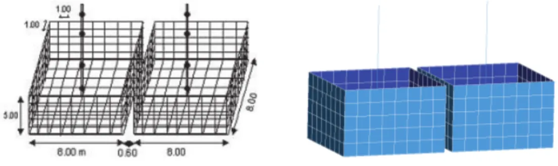
The foundations that constitute the interfaces of SSSI between buildings and the ground are con-sidered rigid and modeled by shell elements. Figure 5 shows the dimensions of these interfaces (left) and the model FE (right) used. The two juxtaposed buildings are spaced 60cm apart.
Figure 5: Simplified model of NUPEC buildings
3.3 Results
Figure 6 displays the transfer functions for the two considered soil columns. Three peaks in the [0: 20] Hz frequency range for the two soil types are identified:
• rigid soil : peaks at 6.5 HZ, 11 Hz and 19.5 HZ; • soft soil: peaks at 5 Hz, 8.3 Hz and 15 Hz.
It is interesting to note that the resonance peaks for soft ground are shifted towards the low fre-quencies compared to the rigid soil. However, the amplifications corresponding to these peaks are stronger for the soft ground than for the rigid one.
Figure 6: Transfer function of soil. The curve in blue represents the rigid soil and the curve in green represents the soft soil.
Concerning the structures, Figure 7 shows the transfer functions obtained for the case of a single building for both types of soil. It illustrates first that considering the soil-structure interaction, the resonance frequency reduces compared to the first fundamental mode of the structure on rigid base (at 28.2Hz). As expected, the lower the rigidity of the soil, the higher is the reduction on the resonance frequency of the building. In addition, the same figure shows an amplification factor of 15 at 12Hz for a rigid ground and of 4.3 at 9.4Hz for the soft ground. As a result, a soft foundation soil has the effect of reducing the amplification of its response on the structure and shifting its fundamental frequency to lower frequencies.
Figure 7: Transfer function for a single building
In this study, only the results in the longitudinal direction is investigated because it is the direction of the alignment of the buildings.
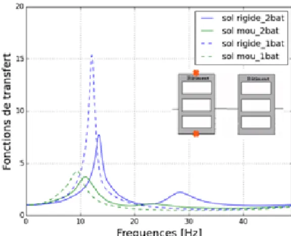
Figure 8 shows the transfer functions for the case of two similar buildings side by side. It is ob-served a peak of 7.6 at 13.3 Hz for a rigid soil and 3.6 at 11 Hz for the soft ground. The second peak is 2.2 at 28 Hz for the rigid soil. For the soft soil this second peak is very low, it is 1 at 22 Hz.
Figure 8: Transfer function for two similar buildings
These figures show that for all two cases, the fact that buildings are based on a soft soil reduce the peak (by a factor of two in the case of two buildings). However, the impact on the amplitude of the transfer function relatively to the soil type for the building-foundation configuration is very low. On the other hand, the presence of the second building has two effects: a reduction in the amplitude of the peak more remarkably for the rigid soil than for the soft soil, and the apparition of a second peak which is more pronounced for the rigid soil.
3.4 Parametric analyses
In this section, the factors which have an influence on the response of structure-soil-structure inter-action for the two soil profiles are investigated. By considering a simple SSSI model (Figure 9), the main aspects affecting SSSI were determined and then varied on the NUPEC model in order to study their influence on this phenomenon [8, 4].
Figure 9: Building model [1]
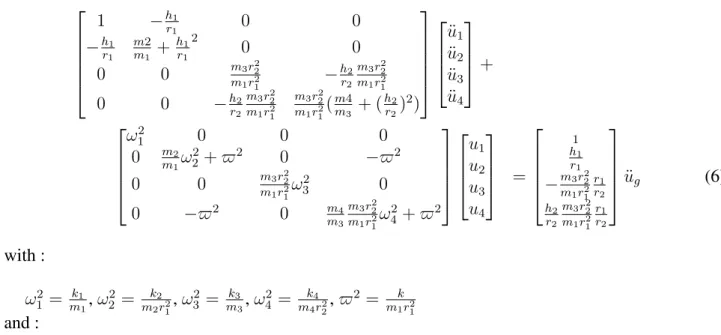
According to Alexander et al. [1], the equation of motion in its matrix form can be expressed as follows:
1 −h1 r1 0 0 −h1 r1 m2 m1 + h1 r1 2 0 0 0 0 m3r22 m1r12 − h2 r2 m3r22 m1r21 0 0 −h2 r2 m3r22 m1r21 m3r22 m1r21 (m4m 3 + ( h2 r2) 2) ¨ u1 ¨ u2 ¨ u3 ¨ u4 + ω2 1 0 0 0 0 m2 m1ω 2 2 + $2 0 −$2 0 0 m3r22 m1r21ω 2 3 0 0 −$2 0 m4 m3 m3r22 m1r21 ω2 4 + $2 u1 u2 u3 u4 = 1 h1 r1 −m3r22 m1r12 r1 r2 h2 r2 m3r22 m1r21 r1 r2 ¨ ug (6) with : ω12 = k1 m1, ω 2 2 = mk22r21, ω 2 3 = mk33, ω 2 4 = mk44r22, $ 2 = k m1r21 and :
m1, m3: masses of buildings 1 and 2 respectively
m2, m4: soil/foundation masses underneath buildings 1 and 2 respectively k1, k3 : stiffnesses of buildings 1 and 2 respectively
k2, k4 : rotational spring stiffnesses of soil beneath buildings 1 and 2 respectively r1, r2 : soil/foundation masses radius of gyration of buildings 1 and 2 respectively h1, h2 : heights of building 1 and 2 respectively
u1, u3 : non-dimensional relative displacement to ground of buildings 1 and 2 respectively u2, u4 : rotation at base of buildings 1 and 2 respectively
k : rotational interaction spring between building 1 and 2
Equation 6 shows the terms that characterize the ”soil-structure” system and which can in particular have an effect on the seismic response of the building. The parameters studied are the following:
• The distance separating the two buildings in order to see from which spacing it is enough to do an ISS modeling only. It is estimated that the variation of the distance separating the two buildings would have an effect on the soil which connects them and which is assimilated to a spring of a certain rigidity k. Indeed, this parameter will change the term $ (interaction circular frequency ratio parameter) which intervenes in the stiffness matrix of the equation of motion; • The height and mass of the adjacent building (m3 and h2) that will change the frequency of this
building (7); f2 = 1 2π r k2 m2 (7) • The embedded depth into the ground of the two buildings. This will change the mass of the
embedded part of the structure (m2and m4).
3.4.1 Influence of separation distance
In order to show the impact of the distance between two buildings on their coupling, and conse-quently the structure-soil-structure interaction, this parameter is varied as follows: 0.60m, 1m, 2m and 5m.
case of a single building. For frequencies below the resonance frequency of the case of a single building, a de-amplification is observed which is more important for small distances. This trend is reversed beyond this frequency and the same remarks are noted in the case of the soft ground. It is also observed that the coupling between the buildings is all the smaller as the distance increases. With this evolution, it is also noted that the amplitude of the second peak decreases. The frequencies at which these peaks occur are always reduced. These remarks apply to both types of soil.
On the other hand, Figure 11 shows the evolution of the resonant frequencies of the reactor build-ing. It is noted that as the distance increases, these frequencies tend towards an asymptote corre-sponding to the resonance frequency of the case of a single building. This confirms the remark above which is true for both soil types.
(a) Ratio TF rigid soil (b) Ratio TF soft soil
Figure 10: Ratio of transfer function : influence of the distance
(a) Rigid soil (b) Soft soil
Figure 11: The evolution of the first peak as a function of the distance between the buildings
Let “a = 8m” be the width of the foundation. It is estimated that, from 65% of this width, the buildings are weakly coupled. Indeed, for the two types of soil, the curve corresponding to a distance of 5 m (62.25% of a) approaches an amplitude equal to 1 which corresponds to the case of a single building (But the buildings are still coupled at this distance).
3.4.2 Influence of mass and height of adjacent building
To quantify the influence of the adjacent building mass (m3), this parameter is varied by consid-ering a lighter (0.5 × m1) and heavier (1.2 × m1) adjacent structure. The weight m1 = 675 tons is
the initial mass tested and is equal for the two buildings spaced 60 cm apart. The choice of these ra-tios was made taking into account the mass rara-tios between the reactor building and adjacent building found in the case of nuclear power plants.
Figure 12 reports the ratio of the transfer functions relatively to the case where the masses are equal, that for the rigid ground the difference is almost non-existent for frequencies below 10Hz, While for the soft ground the variation of the mass in one direction as in the other reduces the ampli-tude of the peaks, and this from 5Hz. From 14Hz for the rigid ground and from 10Hz approximately for the soft ground the difference is more visible. In the case where the second building is heavier, an amplification (more important for the rigid ground) takes place. For the other case, it is a deamplifi-cation that occurs. The comparison is made relatively to the frequencies of the case of two buildings with equal masses.
(a) Ratio TF soft soil (b) Ratio TF soft soil
Figure 12: Ratio of transfer function : influence of mass
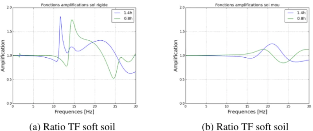
To study how the height of the second building could influence the first one, we compared three cases of figures for a spacing between buildings of 60 cm. In the first case we increased the height by a ratio of 1.4; In the second we lowered this height to 0.8 of the initial height. Finally, we compared these two cases with the one where the height of the two buildings is the same (10.75m). As with considered mass variation, the choice of height ratios results from what can be observed in structures of interest. Figure 13 synthesizes the ratios of the transfer functions of the two cases where the height is changed relatively to the case where it is fixed.
(a) Ratio TF soft soil (b) Ratio TF soft soil
Figure 13: Ratio of transfer function : influence of height
It is noted that the height of the second building has no influence on the building of interest (first building) before 5Hz for the rigid ground and 10Hz for the soft ground. The three curves are super-imposed over a wide range of frequencies and in particular up to 10Hz for soft ground. Beyond these
frequencies, in the case where the second building is higher, an amplification followed by a deampli-fication is observed. The same trend is to be noted for the case where the second building is lower. These remarks are also valid for soft ground but with lower amplitudes.
3.4.3 Influence of depth
For this parameter, two steps are performed:
• the embedded depth of both buildings evenly was modified. Three configurations were tested: surface buildings, embedded at 3m and 5m;
• then, this depth was shifted for both buildings.
Figure 14 illustrates the seismic response of the structure in the embedded situation is lower than that in the shallow situation, as expected. In addition, amplification decreases with depth. In parallel, a shift towards the high frequencies is observed, for both types of soil, in spite of the fact that the amplitude is not the same.
(a) TF rigid soil (b) TF soft soil
Figure 14: Transfer function : influence of depth (equal)
(a) TF rigid soil (b) TF soft soil
Figure 15: Transfer function : influence of depth (staggered)
On the other hand, Figure 14 shows that embedded depth in the soil has the effect of shifting the peak frequencies of the transfer functions to higher values and of modifying the amplitude of these peaks. In the figure 15 is reported the strange form of the transfer function of the case of the shifted depth 5m-3m. This form is probably the result of an error in the numerical calculation.
4 CONCLUSIONS
The present study aims to characterize the SSSI phenomenon, which can be important for the para-seismic design of structures and to highlight the parameters that influence this interaction. To do this, a simple model (NUPEC buildings) was chosen to conduct the SSSI characterization study in the linear domain using the Code Aster and MISS3D coupling.
In the first part of the study, different configurations were analyzed (single building and two build-ings) to compare their seismic behavior. For this analysis, two soil types were considered: soft soil and rigid soil. This comparison made it possible to show that for this case study, the SSSI reduces spectral acceleration in the building of interest. It is also founded that this influence was greater in the case soft foundation soil. On the other hand, to study the sensitivity of the SSSI phenomenon to the quantities characterizing the model, a series of parametric studies were carried out. They related to the distance between the two buildings, the mass and the height of the second building, and the depth of sinking into the ground. The main conclusions drawn from this analysis are:
• Distance : it was noticed that coupling reduces by increasing the distance;
• Mass : amplifies the response of the first building when it is larger and reduces this amplifica-tion when it is smaller;
• Height of the second building, whether larger or smaller, has an impact on the seismic response of the first building. The difference lies in the frequencies at which the peaks occur;
• Depth : the greater the embedded depth, the greater the interaction between the buildings and therefore the reduction of the spectral response. This reduction is higher as the foundation of the second building is deeper.
In perspective to this work, it would be interesting to study an analytical model where the ground between the buildings can be modeled by a spring, in order to compare it to the numerical simulations. ACKNOWLEDGMENTS
The work carried out under the SINAPS@ project receives French funding managed by the Na-tional Research Agency under the program Future Investments (SINAPS@ reference No. ANR-11-RSNR-0022). SINAPS@ is a SEISM Institute project (http://www.institut-seism.fr/en/).
APPENDIX
Table 1: Characteristics of stick model. Young modulus E [MPa] 31,000 Poisson’s ratio ν 0.16 Density ρ [kg/m3] 2028
Table 2: Masses characteristics of stick model.
Masses Height (m) Mass (103Kg) Massic iner. (103Kg.m2) Jxx Jyy Jzz M1 10.375 79.25 410.72 482.34 893.06 M2 7.625 104.09 574.75 694.04 1268.79 M3 4.80 156.71 1020.85 1071.22 2092.07 M4 0.80 316.97 1846.7 1844.02 3690.72
Table 3: Beams characteristics of stick model
Beam Area (m2) Iner. momentum (m4) Shear Coef. Twist Const. (m4)
A Iz Iy Ay Az Jx P1 59.50 341.33 341.33 0.93 0.93 682.70 P2 8.28 39.51 54.77 2.94 1.47 94.30 P3 63.19 341.33 341.33 0.99 0.99 682.70 P4 19.78 148.34 149.14 2.13 2.11 297.50 P5 64.00 341.33 341.33 1.00 1.00 682.70
Table 4: Rigid soil properties
Layer Thickness (m) E(MPa) ρ(Kg/m3) 2β(%) ν
8 1.00 117.9 1770 10 0.386 9 1.00 190.8 1770 10 0.279 10 1.00 207.0 1770 10 0.265 11 1.00 224.2 1770 10 0.251 12 1.00 248.7 1770 10 0.272 1 0.50 614.9 1940 10 0.371 2 2.50 614.9 1940 10 0.371 3 3.00 1 015.1 1940 4 0.415 4 14.00 10 190.0 2210 4 0.386 substratum 27.75 15 010.0 2210 4 0.343
Table 5: Soft soil properties
Layer Thickness (m) E(MPa) ρ(Kg/m3) β(%) ν
8 1.00 78.6 1770 2.019 0.386 9 1.00 100.0 1770 2.871 0.279 10 1.00 81.4 1770 3.673 0.265 11 1.00 73.3 1770 4.072 0.251 12 1.00 71.4 1770 4.314 0.272 1 0.50 496.3 1940 0.574 0.371 2 2.50 481.5 1940 0.641 0.371 3 3.00 819.5 1940 0.573 0.415 4 14.00 10 178.6 2210 0.157 0.386
References
[1] Alexander, N. A., Ibraim, E., and Aldaikh, H. (2013). A simple discrete model for interaction of adjacent buildings during earthquakes. Computers & Structures, 124:1–10.
[2] Alves-Fernandes, V., Banci, F., Devesa, G., Greffet, N., Jacquet, M., Kham, M., Nieto-Ferro, A., Voldoire, F., and Zentner, I. (2017). Dynamic soil-structure interaction modeling strategies applied to kashiwazaki-kariwa nuclear power plant case-study. In COMPDYN 2017 6th ECCO-MAS Thematic Conference on Computational Methods in Structural Dynamics and Earthquake Engineering. Rhodes Island, Greece, 15-17.
[3] Clouteau, D. and Aubry, D. (2005). Miss 6.4: Manuel scientifique. Technical report, Version 1.2. Technical report, ´Ecole Centrale Paris.
[4] Clouteau, D., Broc, D., Dev´esa, G., Guyonvarh, V., and Massin, P. (2012). Calculation methods of structure–soil–structure interaction (3SI) for embedded buildings: Application to NUPEC tests. Soil Dynamics and Earthquake Engineering, 32(1):129–142.
[5] Nieto-Ferro, A. (2013). Interaction sol-structure non-lin´eaire en analyse sismique. PhD thesis, Ecole Centrale Paris.
[6] Pecker, A. (1984). Dynamique des Sols. Presses Ponts et Chauss´ees, Paris.
[7] Semblat, J. F. and Pecker, A. (2009). Waves and vibrations in soils: earthquakes, traffic, shocks, construction works. Waves and vibrations in soils: Earthquakes, Traffic, Shocks, Construction works, pages 500–p.
[8] Zhang, X. (2011). Mod´elisation physique et num´erique des interactions sol-structure sous sollic-itations dynamiques transverses. PhD thesis, Universit´e de Grenoble.
![Figure 1: Simplified modeling of the Soil-Structure interaction model based on the technique of decomposition of the field of study [5]](https://thumb-eu.123doks.com/thumbv2/123doknet/14281448.491656/3.892.331.552.853.1051/figure-simplified-modeling-soil-structure-interaction-technique-decomposition.webp)
![Figure 2: Decomposition of soil-structure interaction problem [6]](https://thumb-eu.123doks.com/thumbv2/123doknet/14281448.491656/4.892.197.703.311.511/figure-decomposition-of-soil-structure-interaction-problem.webp)
![Figure 3: Single embedded building (top) and two identical closely spaced embedded buildings (low) [4]](https://thumb-eu.123doks.com/thumbv2/123doknet/14281448.491656/5.892.93.808.602.799/figure-single-embedded-building-identical-closely-embedded-buildings.webp)