HAL Id: hal-01668625
https://hal.sorbonne-universite.fr/hal-01668625
Submitted on 20 Dec 2017
HAL is a multi-disciplinary open access
archive for the deposit and dissemination of sci-entific research documents, whether they are pub-lished or not. The documents may come from teaching and research institutions in France or abroad, or from public or private research centers.
L’archive ouverte pluridisciplinaire HAL, est destinée au dépôt et à la diffusion de documents scientifiques de niveau recherche, publiés ou non, émanant des établissements d’enseignement et de recherche français ou étrangers, des laboratoires publics ou privés.
A finite fracture model for the analysis of multi-cracking
in woven ceramic matrix composites
J. Li, E. Martin, D. Leguillon, C. Dupin
To cite this version:
J. Li, E. Martin, D. Leguillon, C. Dupin. A finite fracture model for the analysis of multi-cracking in woven ceramic matrix composites. Composites Part B: Engineering, Elsevier, 2018, 139, pp.75-83. �10.1016/j.compositesb.2017.11.050�. �hal-01668625�
A FINITE FRACTURE MODEL FOR THE ANALYSIS OF
MULTI-CRACKING IN WOVEN CERAMIC MATRIX COMPOSITES
J. Li
1, E. Martin
2*, D. Leguillon
3, C. Dupin
2,41 Laboratoire des Sciences des Procédés et des Matériaux, CNRS UPR 3407, Institut Galilée,
Université Paris 13, F-93430 Villetaneuse, France.
2 Laboratoire des Composites Thermo-Structuraux, CNRS UMR 5801, Université de Bordeaux,
F-33600, Pessac, France.
3 Institut Jean le Rond d'Alembert, CNRS UMR 7190, Sorbonne Universités, UPMC Université
Paris 06, F-75005 Paris, France.
4 Nexter-Systems, F-18023, Bourges, France
Abstract :
A finite fracture approach based on the Coupled Criterion is used to analyze multi-cracking in a woven ceramic matrix composite. In-situ micrographic observations obtained during tensile and bending tests performed on chemical vapor infiltrated SiC/SiC samples are utilized to identify cracking mechanisms. A two dimensional finite element model is generated to approximate the actual specimen section geometry including matrix, fiber tows and porosity. Numerical simulations are carried out with a dedicated algorithm to simulate nucleation and propagation of cracks. Comparing the simulation results with experimental ones shows that the model captures the main cracking features.
Keywords : A. Coupled criterion, B. Finite element analysis, C. Ceramic matrix composites
* Corresponding author
Tel +(33)5 56 84 47 00, Fax +(33)5 56 84 12 25 Email address: martin@lcts.u-bordeaux.fr
1. Introduction
Ceramic matrix composites (CMCs) are considered attractive and promising materials for hot parts in advanced fission reactors and gas turbine engines [1]. Their utilization is also assessed for thermal protection systems submitted to very severe environments [2,3]. All-oxide CMCs (typically alumina fibers in porous alumina matrices) are now produced to be used in engine exhaust structures. Non-oxide CMCs, like those consisting of a SiC-based matrix reinforced with SiC fibers, can be used at temperatures up to 1250°C. Low density, high strength and toughness make them candidate to replace superalloys in gas turbine engines in aircrafts [4]. SiC/SiC composites are usually reinforced with two-dimensional fiber fabrics but tri-dimensional geometries have been developed with the help of weaving and braiding techniques to overcome the occurrence of delamination observed within laminated architectures [5]. Various routes can be used to process SiC/SiC composites including a gas phase route like chemical vapor infiltration (CVI) and liquid phase routes like reactive melting infiltration and polymer impregnation and pyrolysis [6]. Depending on this process, a SiC/SiC composite may exhibit significant residual porosity (typically 10-15% for the CVI route) at the microscale (several micrometers) between fibers within the tows and at the mesoscale (i.e. a fraction of a millimeter) between plies [7]. Macro-pores are clearly visible in Fig. 1 which depicts a representative cross-section of a thin SiC/SiC composite elaborated by CVI.
Fig. 1. Cross-sectional optical micrograph of a thin SiC/SiC composite elaborated by CVI
[62]. White regions represent the SiC layers and the darker zones are SiC fiber bundles.
The tensile behavior of SiC/SiC composites at room temperature has been well characterized [8-9]. The stress strain curve exhibits a nonlinear behavior which results from the progressive development of various crack networks. This damage tolerant feature is strongly related to the intensity of the fiber/matrix interface which must be optimized to promote matrix crack deflection [1]. An interphase is deposited onto the fibers in order to control this toughening mechanism [10]. Acoustic emission technique reveals as an appropriate tool to
detect micro-cracking in such materials [11]. Micrographic observations at the mesoscale reveal the development of cracks in the components (matrix, longitudinal and transverse tows) of the composite. Matrix cracking, debonding of the fiber/matrix interface and fiber breaks are also observed within tows at the micro-scale. Fig. 2a shows the cracking of transverse tows within a thin SiC/SiC composite submitted to tensile loading. Final failure is controlled by the strength of the longitudinal tows. Analysis of the bending behavior also indicates cracking that initiates from the tensile side [12]. Compressive cracking of transverse tows is noticed (Fig. 2b) if the tows are located on the outmost compressive side of a specimen submitted to bending [13].
a) b)
Fig. 2. Optical micrographs captured during mechanical testing of a thin SiC/SiC specimen [13]
and revealing cracks in a) transverse tows under tensile test, b) a transverse tow under bending test (arrows indicate the crack generated by compressive failure). In each case, the direction of the applied load is horizontal.
The axial tensile behavior of unidirectional ceramic matrix composites has been analyzed in the literature [14-16]. The elastic response is characterized by a modulus
(
1)
f f f m
V E V E
≈ + − where V is the volume fraction, E is Young’s modulus and subscripts f and m refer to fiber and matrix respectively. Matrix cracking is the first inelastic mechanism which starts at a critical stress depending on the matrix toughness. Thanks to the optimized interfacial properties, matrix crack deflection occurs at the fiber/matrix interface and prevents catastrophic fiber failures. The development of a debonding crack in the vicinity of a matrix crack is accurately described by micromechanical models taking into account interfacial toughness and friction coefficient [17-18]. Raising load increases the matrix crack density which can reach a saturation value. After saturation, the matrix cannot support additional load and the tangent modulus reduces to that of fibers≈V Ef f. Final failure depends on the
development of multiple fiber breaks as described by fragmentation models [19-20]. Extending the analysis to cross-ply laminates submitted to uniaxial tension requires to take into account the multi-cracking of the transverse plies as an additional mechanism. An energetic approach predicts the crack density in the transverse plies as a function of the applied stress [21].
For woven composites, the difficulty comes from the non-uniformity of the local stress field in wavy tows under tensile loading. The analytical approaches already developed for unidirectional composites cannot be easily extended and the use of computational models is necessary to reach a sufficient accuracy. Phenomenological constitutive laws have been developed to reproduce the macroscopic stress-strain response of woven CMCs. One can find plasticity-like models [22] or damage mechanics based models [23-25]. These approaches are dedicated to structural analysis but often require the identification of a large number of parameters which are difficult to link to the actual damage mechanisms. For this purpose, other authors refer to a multiscale analysis based on the modelling of the mechanical behavior of representative cells [26]. A scalar damage mechanics constitutive model can be used for damage initiation and propagation in the matrix while a brittle failure criterion may be preferred for the reinforcement [27]. One dimensional models can also be linked to finite element calculations at the mesoscale to estimate the matrix crack density [28-29]. However, there is a need for computational models capable to produce discrete representation of the damage. As a matter of fact, the cracking pattern must be estimated as it provides valuable information concerning the diffusion of oxidant species. This point is an issue for the lifetime prediction of SiC/SiC composites at high temperature in oxidative atmospheres [30]. For this purpose, one can use new finite element (FE) methods like the extended (XFEM) [31] or the augmented (AFEM) [32] ones which can generate arbitrary discontinuities. Such methods are attractive but reveal very computationally extensive.
The aim of this paper is to propose an alternative approach to predict the multi-cracking of a woven ceramic matrix composite at the mesoscale. For this purpose, a criterion coupling a stress and an energy condition is used to predict the initiation and the propagation of cracks within the framework of finite fracture mechanics. This coupled criterion is associated with a dedicated procedure developed to simulate the evolution of multiple cracks within a brittle structure submitted to a mechanical loading. The use of the same algorithm for crack nucleation and propagation, without predicting initially the nucleation sites, is a significant advance. The paper is organized in the following way. Section 2 introduces the finite fracture approach. Section 3 describes the meso-scale FE model of a representative cell of a woven CMC. Based on experimental observations, several assumptions are made to select the crack families to be
simulated. A tensile test is used to identify the fracture characteristics of each damage mechanism. Section 4 reports the results of the present work. It is checked that the predicted response of the tensile test is close to the experimental one. Then a bending test is simulated to demonstrate that the main damage features are captured by the model.
2. The finite fracture approach
We use here the coupled criterion (CC) which is a finite fracture approach dedicated to predict crack nucleation in the vicinity of a stress concentration in a brittle material.
2.1 The coupled criterion
To analyze the spontaneous formation of a new crack with a finite length, an energy condition and a stress condition must be fulfilled [33]. The first condition is obtained with the help of an energy balance. Comparing the change −δWpin potential energy prior to and after the onset of a crack of length δ to the energy a G ac
δ
(assuming a 2D model so that the widthb of the sample is unity and that Gc is the fracture energy) necessary to create such a crack provides
( )
p inc W c G a G a δ δ δ = − ≥ . (1)Relation (1) introduces the incremental energy release rate Ginc which merges with the usual energy release rate only at the limit δa→0. The second condition states that the tensile stress along the expected crack path prior to failure must exceed the tensile strength
σ
c with( )
r c, 0 r aσ
≥σ
≤ ≤δ
. (2)Matched asymptotic expansions can be used to formulate the CC near a stress singularity like a sharp notch . The tensile stress reads
( )
1 app r r k d λσ
σ
− = , (3a)where λ is the singularity exponent, σapp is the applied stress, d is a characteristic length of the structure and k a scaling coefficient. The incremental energy release rate is given by
( )
2 1 2 inc app Ad a G a E d λδ
δ
σ
− = , (3b)where A is another scaling coefficient.
Combining (1), (2) and (3) provides a closed form of the applied stress
σ
app* at crack initiation( )
1 2 2 1 * 1 c c app k EG k Ad λ λ σ σ − − = . (4)It is to be noted that this formulation coincides with the Griffith criterion in the presence of a
crack 0.5, * c app EG Ad
λ
σ
= = and with the strength criterion for a straight edge
* 1, c app k
σ
λ
σ
= = . The crack increment
* a
δ at onset is proportional to the fracture length
( )
2 c c c EG L σ = with 2 * k c a L A δ = . (5)This length is similar to the critical distance proposed by Taylor [34, 35] but it now does not depend only on the fracture properties but also on the loading geometry. The matched asymptotic expansions rely on the first term of a William series and thus assume that the nucleated crack length is small enough to guarantee that the higher order terms are negligible. If it is not the case, a full field formulation must be used which most of the time requires FE computations. Many applications of the CC can be found in the literature with a wide range of structural applications including free-edge delamination, transverse cracking and notched strength of composite laminates [36-41], adhesive and brazed joints [42-48], crack onset at V-notches [49-51], cracking in ceramic laminates [52-54]. An overview of applications and an extensive list of references can be found in review papers [55-56].
The CC can also be used to analyse multiple cracking. Quesada et al. [57] studied the nucleation of multiple cracks within a stiff inclusion embedded in a soft matrix submitted to a compression loading. In this case the stress condition can be satisfied all over the inclusion and several cracks can nucleate if the available stored energy is high enough. Recently Leguillon and al. [58-59] have proposed to utilize a representative cell which is assumed to reproduce
periodically the cracked behaviour of the structure. Only one crack is introduced in the cell whose length is progressively reduced to simulate the increase of crack density. Doitrand and al. employed the CC to model crack initiation in transverse yarns within a woven glass fibre/epoxy composite [60].
In this paper, a dedicated approach is used to predict the initiation and the propagation of multiple cracks within a 2D linear elastic structure submitted to an increasing loading.
2.2 An algorithm for multiple cracking
The CC is applied to predict the initiation of new cracks and the propagation of existing cracks. The algorithm implemented in a finite element code can be outlined as follows. The stress criterion
σ
I( )
r ≥σ
c (whereσ
I is the first principal stress) is applied to detect zones with a local stress concentration. In such zones, we identify a potential crack path which starts from the point whereσ
I is locally maximal and follows a principal stress trajectory. Fulfilment ofthe energy criterion activates a crack among the potential cracks. The selected crack must maximize the incremental energy release rate Ginc and fulfil the energy criterion Ginc ≥Gc. Creation of a new crack is obtained by deleting the elements along the predicted crack path. Following this algorithm, a dedicated 2D FE procedure has been developed and checked against various numerical examples [61]. It was shown that this numerical model presents several advantages, such as its capacity to predict both crack initiation and crack growth and to track automatically the crack paths. Its robustness and its weak mesh-dependence have been tested. In return, the deleting-element technique requires a sufficiently fine mesh such that eliminated elements are able to represent a crack. This numerical model will be employed in the following sections to simulate multiple cracking at the mesoscale within a representative cell of a woven CMC.
3. The meso-scale model
We focus on the mechanical behavior of SiC/SiC composites elaborated by CVI. As mentioned in the introduction, various authors have studied the tensile behavior of this type of CMCs and observed a sequential development of damage mechanisms. More recently, the microstructure and the tensile properties of thin SiC/SiC composites with a self-healing matrix
have been reported [62-63]. In situ micrographic observations at the meso-scale performed during tensile tests have evidenced the successive development of three families of cracks [13]: i) Matrix (M) cracking starts for an applied strainε ≥0.06%. Early matrix cracking is observed in the vicinity of macro-pores,
ii) Tensile cracking of transverse tows (TTt) is observed at an applied strainε ≥0.14%. One or two cracks are typically observed within the cracked transverse tows as illustrated in Fig. 2a, iii) Cracking of longitudinal tows (LT) is only noticed for ε ≥0.45%in the last stage of the tensile curve.
Debonding at the interface between matrix and tows is likely to occur but it is difficult to detect and will not be considered here. Fig. 3a shows a typical tensile load response and indicates the successive triggering of the damage mechanisms. The corresponding cumulated acoustic events (AE) are plotted versus the applied stress on Fig. 3b. Former studies [11] have shown that the cumulative AE is related to the number of formed cracks and this curve is thus representative of the kinetics of cracking.
Four-point bending tests were also performed on the same material [13]. In situ micrographic observations reveal similar mechanisms (M, TTt and LT cracking) only on the tensile side of the sample. Compression cracks (TTc) are observed in the transverse tows on the compressive side and trigger the final fracture (Fig. 2b).
a) b)
Fig. 3. Tensile testing of a SiC/SiC specimen: a) strain-stress response and b) cumulated AE
(normalized by its maximum value) versus the applied stress. The onset (as revealed by in-situ observations) of the three main cracking mechanisms (matrix (M), transverse tows (TTt),
longitudinal tows (LT)) are indicated.
In order to analyze the mechanical behavior of this composite, a 2D FE model of an idealized unit cell (length L and thickness t) is created with dedicated tools [64]. As depicted by Fig. 4, the cross section of the composite consists of two layers in the warp direction and
0 50 100 150 200 250 300 350 0 0.2 0.4 0.6 0.8 1 S TR E S S (M P a) STRAIN (%) M TTt LT 0 0.2 0.4 0.6 0.8 1 0 50 100 150 200 250 300 350 NO RM AL IZ E D C UM UL A T E D A E STRESS (MPa) M TTt LT
three layers in the weft direction. The transverse tows are taken to have an elliptical cross-section. Each tow is assumed to be identical to every other one. Closed macro-pores are observed between the fiber bundles. The sizes of each component (matrix, longitudinal and transverse tows) are representative of the microstructure. The mesh is composed of about 24000 triangular elements with an average mesh size h = 20 µm.
Fig. 4. Representation of the FE cell with a thickness t=1.2 mm and a length L=10 mm; the
colors allow to identify each component including the matrix (red), the transverse (green) and the longitudinal (yellow) tows (For interpretation of the references to color in this figure legend, the reader is referred to the web version of this article). Direction 1 corresponds to the in plane warp direction and direction 2 is the thickness direction.
A tensile test is simulated by applying an imposed displacement (along direction 1) at the right boundary while the displacement (along direction 1) of the nodes of the left boundary is prescribed to zero (Fig. 5a). The 4-point bending load follows the geometry depicted in Fig. 5b. The outer length and the inner span are respectively denoted L and .
a) b)
Fig. 5. Boundary conditions applied to the mesoscale model to simulate a) a tensile test, b) a
4-point bending test.
The effective elastic properties of each component are reported in Table 1. The matrix is assumed to be isotropic while a tow is considered as transversely isotropic. Note that the SiC based matrix is not made with monolithic SiC (to make it self-healing) which explains that its modulus is lower than 450 GPa. The elastic properties of the fiber bundles are estimated with the help of a dedicated homogenization procedure using a representative cell [65].
Table 1 adds the fracture properties of each component which are a priori unknown and are estimated with the help of a trial and error procedure: tensile tests are performed on the
1 2 t L L
representative cell and the relevant fracture properties are estimated in order to observe the sequential development of damage already mentioned (Fig. 3). It must be pointed out that this procedure is approximate and does not provide a unique couple
(
σ
c,Gc)
for each mechanism. However, the estimated value 60 Jm-2 of the fracture energy of the matrix is close to typical values (20-40 Jm-2) measured for sintered SiC [66]. The high value (1700 MPa) of the tensile strength of the longitudinal tow must be correlated with the typical values (800-1200 MPa) [67-68] measured for “minicomposites” which are often considered as representative of a singlefiber bundle. Table 1 also indicates the values of the characteristic fracture length
( )
11 2 c c c E G L σ =for each mechanism. This length must be compared with the mesh size h in order to capture accurately the crack increment at onset. If matrix and transverse tows are involved, the
comparison is satisfactory as
15
c
L
h< . This is clearly not the case for longitudinal tows for which
the high tensile strength implies a smaller fracture length. It is thus likely that the prediction will not be as precise for this mechanism.
Table 1
Properties used for the FE model at the mesoscale.
11
E E22 ν12 G12
σ
c cG Lc
(GPa) (GPa) (GPa) (MPa) (Jm-2) (µm)
Matrix 320 320 0.15 139 140 60 979.6
Transverse tows 139 139 0.117 66 120 40 386.1
Longitudinal tows 198 139 0.166 75 1700 400 27.4
4. Results and discussion
The results obtained with the simulation of a monotonic tensile test are first presented. Fig. 6 depicts the predicted crack network for three increasing values of the applied strain. As expected matrix cracking (M) is the first activated mechanism which develops as a consequence of the stress concentration induced by macro-pores (Fig. 6a). The following mechanism is tensile cracking of transverse tows (TTt) as shown in Fig. 6b. The final crack network (Fig. 6c) reveals cracking of longitudinal tows (LT). It is interesting to notice the accumulation of matrix cracks near the macro-pores and at the interface between matrix and longitudinal tows that may be representative of the occurrence of debonding. The corresponding simulated strain-stress response is plotted against the experimental response in Fig. 7a. The smaller length L=10 mm
of the FE model (as compared with the 100 mm length of the real sample submitted to the tensile test) is responsible for the saw tooth-like response. A good agreement is observed up to an applied strain of 0.7%. This figure also plots the simulated response if the cracking of tows is ignored. Considering matrix cracking alone is clearly not sufficient to match the experimental response. The cumulated length of cracks (normalized by the total length attained) is plotted versus the applied stress and compared with normalized cumulated AE in Fig. 7b. The kinetics of cracking is well captured by the numerical simulation up to an applied stress of 200 MPa. Beyond this limit, the inaccuracy may be attributed to the unreliability of the model to represent the cracking of longitudinal tows.
a) ε =0.08%
b) ε =0.32%
c) ε =0.73%
Fig. 6. Representation of the crack network resulting from the simulation of a tensile test for
three values of the applied strain. The arrows indicate typical cracks for each mechanism.
M
LT TTt
a) b)
Fig. 7. Simulation of a tensile test and comparison with the experimental data: a) Strain stress
response. The black curve is the experimental one and the colored ones are simulated responses (the green curve is obtained if only matrix cracking is considered), b) Cumulated acoustic emission (experimental) and cumulated crack length (simulated) versus the applied stress. The data are normalized by their maximum values reached for an applied stress of 200 MPa.
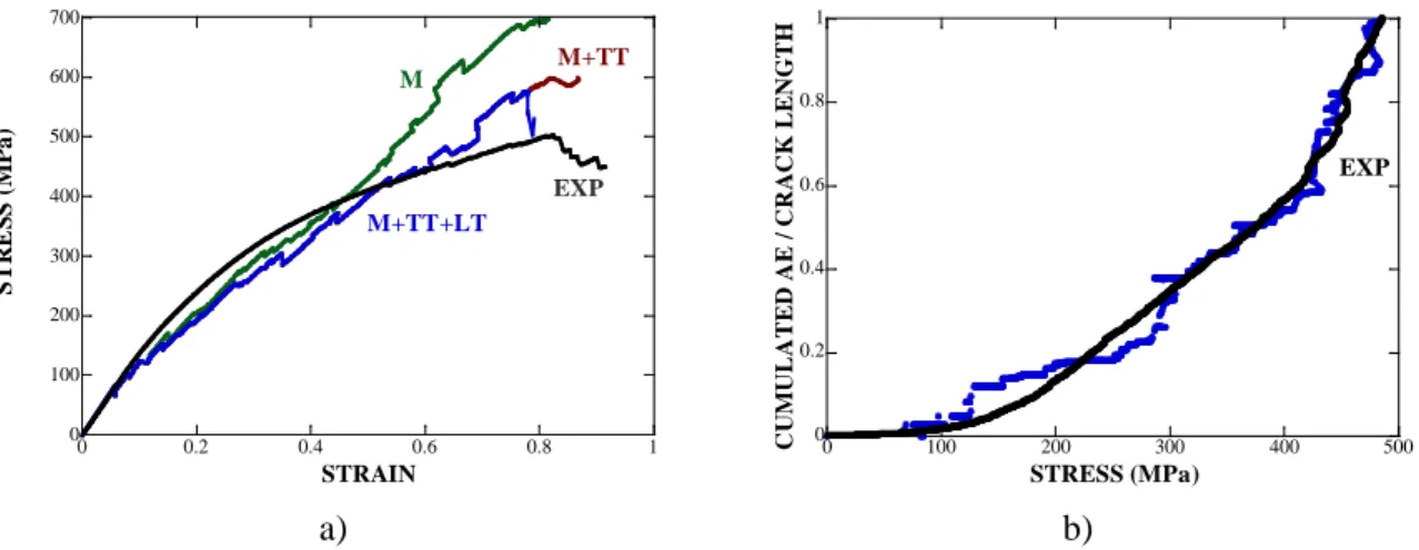
Keeping the same fracture properties for each component, the representative cell is now submitted to a monotonic four point bending test with the geometry indicated in Fig. 5b. The selected dimensions are L=10 mm, =6 mm, t=1.2 mm, width b=1 mm. In order to avoid the undesirable damages due to the punctual loading, all the components located beyond the inner span are assumed to be unbreakable in the simulations. Fig. 8 represents the predicted crack networks for three increasing values of the applied displacement. As expected, matrix cracks are first observed at the outmost tensile side (Fig. 8a). Increasing the displacement activates cracking of transverse tows but no crack can be observed at the compressive side (Fig. 8b). Finally, a main crack across nearly all the components including the longitudinal tows is formed. Moreover, compressive failure (TTc) is observed within transverse tows for a high level of applied displacement (Fig. 8c). This prediction is in agreement with the experimental observation (Fig. 2b).
To represent the predicted mechanical response, the nominal stress σ and strain ε are introduced as given by the classical beam theory
2 M t I σ = , 2 2 2 V t V ε = + with 2 2 P L M = − (6) 0 50 100 150 200 250 300 350 400 0 0.2 0.4 0.6 0.8 1 S TR E S S (M P a) STRAIN (%) M+TT+LT M EXP M+TT TTt LT M 0 0.5 1 1.5 0 50 100 150 200 250 300 CU M UL AT E D AE / CRA CK L E NG T H STRESS (MPa) EXP
where P is the applied load, b is the specimen width and V is the relative deflection defined by V =Vmax− (V0 Vmax is the maximum deflection and V is the deflection at the loading point), 0
I is the moment of inertia which is computed taking into account the geometry of the cell. In order to compare the predicted mechanical response with an experimental one performed on a sample with a different size (L=55 mm, =25 mm, t=1.9 mm, width b=10 mm), a dedicated procedure is required. As detailed in the Appendix, beam theory is used to estimate V (and 0
thus V ) from the experimental data
(
P V, max)
. Equation (6) then provides nominal stress andstrain and in this case the moment of inertia is simply given by
3
12
bt
I = . Fig. 9a likens the predicted stress-strain curve with the experimental one. In spite of the larger size of the sample (as compared with the representative cell), a reasonable agreement is demonstrated. Comparing the simulated response with and without the cracking of transverse tows (TTt) evidences the influence of this mechanism on the mechanical response. The other mechanisms (LT and TTc) are only observed at the end of the simulation. Furthermore comparing the cumulated crack length (simulated) and the cumulated AE (experimental) in Fig. 9b also demonstrates a good agreement and shows that the model is able to capture the kinetics of cracking.
(a) ε = 0.21%
(b) ε = 0.49%
(c) ε = 0.79%
Fig. 8. The crack network resulting from the simulation of a bending test for three values of the
relative deflection.
M TTt
TTc
a) b)
Fig. 9. Simulation of a bending test: a) deflection-stress response. The black curve is the
experimental one and the colored ones are simulated responses (the green curve is obtained if only matrix cracking is considered), b) Cumulated acoustic emission (experimental) and cumulated crack length (simulated) versus the applied stress. The data are normalized by their maximum values reached at σ =485 MPa.
5. Conclusion
The present work uses a finite fracture approach to analyze multiple cracking at the mesoscale within a unit cell representative of a woven CMC. The coupled criterion which combines a strength and a toughness condition is associated with a dedicated algorithm to predict the nucleation and the propagation of cracks. Three families of cracks are introduced in the model: matrix cracking, transverse and longitudinal tow cracking. Recent experimental results obtained from tensile tests performed on thin SiC/SiC composites elaborated by CVI are used: in-situ observations show the sequential development of the three cracking mechanisms under tensile loading and allow to determine the corresponding applied strain. A bi-dimensional FE model representative of the SiC/SiC microstructure is build. Using the finite fracture approach to simulate a tensile test and comparing with the experimental data permits to identify the fracture properties (strength and toughness) for each mechanism. Kinetics of cracking is well captured by the model as confirmed by the similar evolution of cumulated acoustic events (experimental data) and cumulated crack lengths (simulation data) versus the applied stress. Submitting now the unit cell to a four-point bending test shows that the previously mentioned mechanisms only develop at the tensile side. An additional mechanism (compressive cracking
0 100 200 300 400 500 600 700 0 0.2 0.4 0.6 0.8 1 S TR E S S (M P a) STRAIN EXP M+TT+LT M M+TT 0 0.2 0.4 0.6 0.8 1 0 100 200 300 400 500 CU M UL AT E D AE / CRA CK L E NG T H STRESS (MPa) EXP
of transverse tow) is predicted during the last stage of the loading. Those results are in good agreement with the experimental observations.
We believe that our approach provides a simple and robust method to predict discrete damage in CMC. Convergence problems which arise from non-linear methods like cohesive zone models are avoided. Future work will incorporate the debonding mechanism at the matrix/tow interface. Further simulations with a larger unit cell and a decreasing mesh size are also necessary to increase accuracy. The influence of microstructural features on cracking patterns and mechanical response will be investigated.
APPENDIX
It is here assumed that i) the beam remains undamaged for 0
2 L x w −
≤ ≤ = with a bending modulus E , ii) the beam only damages for 1
2
L
w≤ ≤ with a bending modulus x E decreasing 2
with the applied load.
In order to estimate V =Vmax− , use is made of the following differential equations V0 2 1 2 1 2 2 2 2 , 0 2 , 2 2 d V Px x w dx E I d V Pw L w x dx E I = − ≤ ≤ = − ≤ ≤ . (A.1)
Boundary and continuity conditions write
(
)
(
)
(
)
(
)
(
)
1 1 2 2 1 2 0 0, 0, 2 V x V x w V x w dV L dV dV x x w x w dx dx dx = = = = = = = = = = . (A.2)Solving (A.1) and (A.2) provides
(
)
3 2 0 1 1 2 3 2 2 max 2 1 2 6 2 2 2 6 4 4 Pw Pw L V V x w w E I E I L Pw Pw L V V x w E I E I = = = + − = = = + − (A.3)2 2 1 max 04 4 3 P w L w E V I = − , (A.4) where max 0 P V
is the initial slope of the load-deflection curve. The bending modulus E depends on the applied load with 2
1 2 3 2 2 max 1 4 4 6 Pw L Pw E w V I E I − = − − . (A.5)
The experimental data
(
P V, max)
allow to estimate(
E E V1, 2, 0)
with the help of (A.4), (A.5), (A.3).References
[1] Naslain R.Design, preparation and properties of non-oxide CMCs for application in engines and nuclear reactors : an overview. Compos Sci Technol 2004;64:155-170.
[2] Triantou K, Perez B, Marinou A, Florez S, Mergia K, Vekinis G, et al. Performance of cork and ceramic matrix composite joints for re-entry thermal protection structures. Composites Part B: Engineering 2017;108:270–8. doi:10.1016/j.compositesb.2016.09.104.
[3] Wang Y, Chen Z, Yu S, Awuye DE, Li B, Liao J, et al. Improved sandwich structured ceramic matrix composites with excellent thermal insulation. Composites Part B: Engineering 2017;129:180–6. doi:10.1016/j.compositesb.2017.07.068.
[4] Zok FW. Ceramic-matrix composites enable revolutionary gains in turbine engine efficiency. American Ceramic Society Bulletin, 2016;95:22-28.
[5] Berdoyes I, Thebault J, Bouillon E. Improved SiC/SiC and C/C materials applications parts. In: Proceedings of the European congress on advanced materials and processes, EUROMAT 2005, Prague, Czech Republic, 5–8 September 2005.
[6] Yang LW, Liu HT, Cheng HF. Processing-temperature dependent micro- and macro-mechanical properties of SiC fiber reinforced SiC matrix composites. Composites Part B: Engineering 2017;129:152–61. doi:10.1016/j.compositesb.2017.07.079.
[7] Peters PWM, Martin E, Pluvinage P. The influence of porosity on the engineering moduli of fibre reinforced ceramics (SiC/SiC). Composites, 1995;26:108-114
[8] Prouhet S, Camus G, Labrugère C, Guette A, Martin E. Mechanical Characterization of Si–C (O) Fiber/SiC (CVI) Matrix Composites with a BN–Interphase. Journal of the American Ceramic Society 1994;77:649–656. [9] Ogasawara T, Ishikawa T, Ito H, Watanabe N, Davies IJ. Multiple cracking and tensile behavior for an orthogonal 3-D woven Si-Ti-C-O fiber/Si-Ti-C-O matrix composite. J. Am. Ceram. Soc. 2001; 84:1565-1574. [10] Kabel J, Yang Y, Balooch M, Howard C, Koyanagi T, Terrani KA, et al. Micro-mechanical evaluation of SiC-SiC composite interphase properties and debond mechanisms. Composites Part B: Engineering 2017;131:173–83. doi:10.1016/j.compositesb.2017.07.035.
[11] Morsher GN, Godin N. Use of Acoustic Emission for Ceramic Matrix Composites. Ceramic Matrix Composites Materials, Modeling and Technology, Edited by N.P. Bansal and J. Lamon, Wiley 2015; 20:571-590. [12] Kobayashi S., Morohoshi A, Wakayama S, Kogo Y, Hatta H. The effect of specimen width on the bending strength of ceramic matrix textile composites. Composites : Part B. 2005;36 : 359-364.
[13] Dupin C. PhD Thesis (in French), University of Bordeaux, 2013.
[14] He MY, Wu BX, Evans AG, Hutchison JW. Inelastic strains due to matrix cracking in unidirectional fiber-reinforced composites. Mechanics of Materials 1994;18:213-229
[15] Ismar IH, Reinert D-IU. Modelling of the micromechanical behaviour of unidirectional fibre-reinforced ceramics by the example of SiC/SiC. Archive of Applied Mechanics 1995;66:34–44.
[16] Chateau C, Gélébart L, Bornert M, Crépin J, Caldemaison D, Sauder C. Modeling of damage in unidirectional ceramic matrix composites and multi-scale experimental validation on third generation SiC/SiC minicomposites. Journal of the Mechanics and Physics of Solids 2014;63:298–319. doi:10.1016/j.jmps.2013.09.001.
[17] Marshall DB. Analysis of fiber debonding and sliding experiments in brittle matrix composites. Acta metal. Mater. 1992;3:427-441
[18] Peters PWM, Martin E, Quenisset JM. Slip and frictional shear stresses in ceramic matrix composites. Journal of Composite Materials 1995;29:550-572
[19] Neumeister JM. A constitutive law for continuous fiber-reinforced brittle–matrix composites with fiber fragmentation and stress recovery. J. Mech. Phys. Solids 1993;41:1383–1404
[20] Hui CY, Phoenix SL, Ibnabdeljalil M, Smith RL. An exact closed-form solution for fragmentation of weibull fibers in a single filament composite with applications to fiber-reinforced ceramics. J.Mech.Phys.Solids 1995;43:1551–1585.
[21] Xia ZC, Hutchinson JW. Matrix cracking of cross-ply ceramic composites. ActaMetall Mater 1994;42:1933– 45.
[22] Rajan VP, Shaw JH, Rossol MN, Zok FW. An elastic–plastic constitutive model for ceramic composite laminates. Composites Part A: Applied Science and Manufacturing 2014;66:44–57. doi:10.1016/j.compositesa.2014.06.013.
[23] Gasser A, Ladevèze P, Poss M. Damage mechanisms of a woven SiC/SiC composite: modelling and identification. Comp. Sci. Tech. 1996; 56:779-784.
[24] Camus G. Modelling of the mechanical behavior and damage processes of fibrous ceramic matrix composites: application to a 2-D SiC/SiC. International Journal of Solids and Structures 2000;37:919–942.
[25] Marcin L, Maire J-F, Carrère N, Martin E. Development of a Macroscopic Damage Model for Woven Ceramic Matrix Composites. International Journal of Damage Mechanics 2010;20:939–57. doi:10.1177/1056789510385259.
[26] Grujicic M, Snipes J, Galgalikar R, Yavari R, Avuthu V, Ramaswami S. Multi-length-scale derivation of the room-temperature material constitutive model for SiC/SiC ceramic-matrix composites. Proceedings of the Institution of Mechanical Engineers, Part L: Journal of Materials: Design and Applications 2015. doi:10.1177/1464420715600002.
[27] Borkowski L, Chattopadhyay A. Multiscale model of woven ceramic matrix composites considering manufacturing induced damage. Composite Structures 2015;126:62–71. doi:10.1016/j.compstruct.2015.02.015. [28] Gowayed Y, Ojard G, Santhosh U, Jefferson G. Modeling of crack density in ceramic matrix composites. Journal of Composite Materials 2014. doi:10.1177/0021998314545188.
[29] Santhosh U, Ahmad J, Ojard G, Miller R, Gowayed Y. Deformation and damage modeling of ceramic matrix composites under multiaxial stresses. Composites Part B: Engineering 2016;90:97–106. doi:10.1016/j.compositesb.2015.12.017.
[30] Gowayed Y, Abouzeida E, Smyth I, Ojard G, Ahmad J, Santhosh U, et al. The role of oxidation in time-dependent response of ceramic–matrix composites. Composites Part B: Engineering 2015;76:20–30. doi:10.1016/j.compositesb.2015.02.005.
[31] Moës N, Dolbow J, Belytschko T. A finite element method for crack growth without remeshing, International Journal of Numerical Methods in Engineering 1999;46:131–150.
[32] Naderi M, Jung J, Yang QD. A three dimensional augmented finite element for modeling arbitrary cracking in solids. International Journal of Fracture 2016. doi:10.1007/s10704-016-0072-3.
[33] Leguillon D. Strength or toughness? A criterion for crack onset at a notch, European Journal of Mechanics A/Solids 2002;21:61–72.
[34] Taylor D. The theory of critical distances: a new perspective in fracture mechanics. London: Elsevier; 2007. [35] Ibáñez-Gutiérrez FT, Cicero S, Carrascal IA, Procopio I. Effect of fibre content and notch radius in the fracture behaviour of short glass fibre reinforced polyamide 6: An approach from the Theory of Critical Distances. Composites Part B: Engineering 2016;94:299–311. doi:10.1016/j.compositesb.2016.03.064.
[36] Martin E, Leguillon D, Carrère N. A twofold strength and toughness criterion for the onset of free-edge shear delamination in angle-ply laminates. International Journal of Solids and Structures 2010;47:1297–305. doi:10.1016/j.ijsolstr.2010.01.018.
[37] Hebel J, Dieringer R, Becker W. Modelling brittle crack formation at geometrical and material discontinuities using a finite fracture mechanics approach. Engineering Fracture Mechanics 2010;77:3558–72. doi:10.1016/j.engfracmech.2010.07.005.
[38] Camanho PP, Erçin GH, Catalanotti G, Mahdi S, Linde P. A finite fracture mechanics model for the prediction of the open-hole strength of composite laminates. Composites Part A: Applied Science and Manufacturing 2012;43:1219–1225. doi: 10.1016/j.compositesa.2012.03.004
[39] Martin E, Leguillon D, Carrère N. A coupled strength and toughness criterion for the prediction of the open hole tensile strength of a composite plate. International Journal of Solids and Structures 2012;49:3915–22. doi:10.1016/j.ijsolstr.2012.08.020.
[40] García IG, Mantič V, Blázquez A, París F. Transverse crack onset and growth in cross-ply laminates under tension. Application of a coupled stress and energy criterion. International Journal of Solids and Structures 2014;51:3844–3856. doi: 10.1016/j.ijsolstr.2014.06.015
[41] García IG, Carter BJ, Ingraffea AR, Mantič V. A numerical study of transverse cracking in cross-ply laminates by 3D finite fracture mechanics. Composites Part B: Engineering 2016. doi:10.1016/j.compositesb.2016.03.023. [42] Nguyen LM, Leguillon D, Gillia O, Riviere E. Bond failure of a SiC/SiC brazed assembly. Mechanics of Materials 2012;50:1–8. doi:10.1016/j.mechmat.2012.03.001.
[43] Moradi A, Leguillon D, Carrère N. Influence of the adhesive thickness on a debonding – An asymptotic model. Engineering Fracture Mechanics 2013;114:55–68. doi:10.1016/j.engfracmech.2013.10.008.
[44] Moradi A, Carrère N, Leguillon D, Martin E, Cognard J-Y. Strength prediction of bonded assemblies using a coupled criterion under elastic assumptions: Effect of material and geometrical parameters. International Journal of Adhesion and Adhesives 2013;47:73–82. doi:10.1016/j.ijadhadh.2013.09.044.
[45] Weißgraeber P, Becker W. Finite Fracture Mechanics model for mixed mode fracture in adhesive joints. International Journal of Solids and Structures 2013;50:2383–94. doi:10.1016/j.ijsolstr.2013.03.012.
[46] Weißgraeber P, Felger J, Talmon l’Armée A, Becker W. Crack initiation in single lap joints: effects of geometrical and material properties. International Journal of Fracture 2015;192:155–66. doi:10.1007/s10704-015-9992-6.
[47] Carrère N, Martin E, Leguillon D. Comparison between models based on a coupled criterion for the prediction of the failure of adhesively bonded joints. Engineering Fracture Mechanics 2015;138:185–201. doi:10.1016/j.engfracmech.2015.03.004.
[48] Martin E, Vandellos T, Leguillon D, Carrère N. Initiation of edge debonding: coupled criterion versus cohesive zone model. International Journal of Fracture 2016;199:157–68. doi:10.1007/s10704-016-0101-2. [49] Yosibash Z, Priel E, Leguillon D. A failure criterion for brittle elastic materials under mixed-mode loading. International Journal of Fracture 2006;141:291–312. doi:10.1007/s10704-006-0083-6.
[50] García IG, Leguillon D (2012) Mixed-mode crack initiation at a v-notch in presence of an adhesive joint. International Journal of Solids and Structures 49:2138–2149. doi: 10.1016/j.ijsolstr.2012.04.018
[51] Sapora A, Cornetti P, Carpinteri A (2013) A Finite Fracture Mechanics approach to V-notched elements subjected to mixed-mode loading. Engineering Fracture Mechanics 2013; 97:216-226. doi: 10.1016/j.engfracmech.2012.11.006
[52] Leguillon D, Martin E. The strengthening effect caused by an elastic contrast—part II: stratification by a thin stiff layer. International Journal of Fracture 2012;179:169–78. doi:10.1007/s10704-012-9785-0.
[53] Leguillon D, Martin E. The strengthening effect caused by an elastic contrast—part I: the bimaterial case. International Journal of Fracture 2012;179:157–67. doi:10.1007/s10704-012-9787-y.
[54] Leguillon D, Martin E, Ševeček O, Bermejo R. Application of the coupled stress-energy criterion to predict the fracture behaviour of layered ceramics designed with internal compressive stresses. European Journal of Mechanics - A/Solids 2015;54:94–104. doi:10.1016/j.euromechsol.2015.06.008.
[55] Weißgraeber P, Leguillon D, Becker W. A review of Finite Fracture Mechanics: crack initiation at singular and non-singular stress raisers. Archive of Applied Mechanics 2015. doi:10.1007/s00419-015-1091-7.
[56] Martin E, Leguillon D, Carrère N. Finite fracture mechanics: a useful tool to analyze cracking mechanisms in composite materials. Chapter 19, pp. 529-548, Fifty Years of Progress in Carbon Fiber Research, Edited by P.W.R Beaumont & C. Soutis, Springer 2016
[57] Quesada D, Leguillon D, Putot C. Multiple failures in or around a stiff inclusion embedded in a soft matrix under a compressive loading. European Journal of Mechanics - A/Solids 2009;28:668–79. doi:10.1016/j.euromechsol.2009.03.001.
[58] Leguillon D, Lafarie-Frenot MC, Pannier Y, Martin E. Prediction of the surface cracking pattern of an oxidized polymer induced by residual and bending stresses. International Journal of Solids and Structures 2016;91:89–101. doi:10.1016/j.ijsolstr.2016.04.019.
[59] Leguillon D, Li J, Martin E. Multi-cracking in brittle thin layers and coatings using a FFM model. European Journal of Mechanics - A/Solids 2017;63:14–21. doi:10.1016/j.euromechsol.2016.12.003.
[60] Doitrand A, Fagiano C, Hild F, Chiaruttini V, Mavel A, Hirsekorn M. Mesoscale analysis of damage growth in woven composites. Composites Part A: Applied Science and Manufacturing 2017. doi:10.1016/j.compositesa.2017.02.018.
[61] Li J, Leguillon D. Finite element implementation of the coupled criterion for numerical simulations of crack initiation and propagation in brittle materials. Theoretical and Applied Fracture Mechanics 2017.doi:10.1016/j.tafmec.2017.07.010
[62] Herb V, Couégnat G, Martin E. Damage assessment of thin SiC/SiC composite plates subjected to quasi-static indentation loading. Composites : Part A 2010;41:1677-1685.
[63] Herb V, Martin E, Couégnat G. Damage analysis of thin 3D-woven SiC/SiC under low velocity impact loading. Composites : Part A 2012;43:247-253.
[64] Couégnat G, Ros W, Haurat T, Germain C, Martin E, Vignoles G. An integrated virtual material approach for ceramic matrix composites. Paper ICACC-FS2-026-2012, 36th International Conference on Advanced Ceramics & Composites (ICACC), 22-27 Janvier 2012, Daytona Beach, USA
[65] Couégnat G, Martin E, Lamon J. 3D Multiscale modeling of the mechanical behavior of woven composite materials. Ceram. Eng. Sci. Proc. 2010; 31:185-194.
[66] Lorrette C, Réau A, Briottet L. Mechanical properties of nanostructured silicon carbide consolidated by spark plasma sintering. Journal of the European Ceramic Society 2013;33:147–56. doi:10.1016/j.jeurceramsoc.2012.07.030.
[67] Sauder C, Brusson A, Lamon J. Influence of Interface Characteristics on the Mechanical Properties of Hi-Nicalon type-S or Tyranno-SA3 Fiber-Reinforced SiC/SiC Minicomposites: Influence of Interface Characteristics on the Mechanical Properties. International Journal of Applied Ceramic Technology 2010;7:291–303. doi:10.1111/j.1744-7402.2010.02485.x.
[68] Almansour A, Maillet E, Ramasamy S, Morscher GN. Effect of fiber content on single tow SiC minicomposite mechanical and damage properties using acoustic emission. Journal of the European Ceramic Society 2015;35:3389–99. doi:10.1016/j.jeurceramsoc.2015.06.001.
![Fig. 1. Cross-sectional optical micrograph of a thin SiC/SiC composite elaborated by CVI [62]](https://thumb-eu.123doks.com/thumbv2/123doknet/13312210.398914/3.892.129.772.697.890/fig-cross-sectional-optical-micrograph-sic-composite-elaborated.webp)
![Fig. 2. Optical micrographs captured during mechanical testing of a thin SiC/SiC specimen [13]](https://thumb-eu.123doks.com/thumbv2/123doknet/13312210.398914/4.892.136.771.382.652/fig-optical-micrographs-captured-mechanical-testing-sic-specimen.webp)