Application of Microfluidic Emulsion Technology to
Biochemistry, Drug Delivery and Lab-on-a-Chip Programmability
byJohn Paul Urbanski B.A.Sc. Mechanical Engineering
University of Waterloo, 2003
SUBMITTED TO THE DEPARTMENT OF MECHANICAL ENGINEERING IN PARTIAL FULFILLMENT OF THE REQUIREMENTS FOR THE DEGREE OF
MASTER OF SCIENCE IN MECHANICAL ENGINEERING AT THE
MASSACHUSETTS INSTITUTE OF TECHNOLOGY May 2005
C 2005 Massachusetts Institute of Technology All rights reserved
Signature of Author...
Certified by ...
Department o4/Mechanical Engineering May 6, 2005
Todd Thorsen Assistant Professor of Mechanical Engineering ,A Thesis Supervisor
A ccepted by ...
Professor Lallit Anand Graduate Officer, Department of Mechanical Engineering
MARKER
MASsACHUSETTS INS E OF TECHNOLOGY
JUN
16
2005
Application of Microfluidic Emulsion Technology to
Biochemistry, Drug Delivery and Lab-on-a-Chip Programmability
byJohn Paul Urbanski
Submitted to the Department of Mechanical Engineering on May 6, 2005 in Partial Fulfillment of the Requirements for the Degree of Master of Science in Mechanical
Engineering
Abstract
This research applies microfluidic emulsion technology to three diverse problems;
biochemistry, drug delivery and lab-on-a-chip programmability. These subjects represent distinct research programs, but the underlying physics of droplet formation, transport and control at low values of the Reynolds and Capillary numbers in multiphase microfluidics allows them to be considered in parallel and supports the flexibility of this technology. Within these stamp-sized elastomeric polydimethylsiloxane (PDMS) microfluidic devices, pressurized immiscible fluids may be combined at a junction of two or more microchannels, combining crossflow and viscoelastic shear, to generate emulsions. Droplet sizes may be tuned from nanometers to microns in diameter, controlled by device geometry and hydrodynamic flow characteristics.
The application of droplets as individual bioreactors for biochemical assays is first explored at the device and external sensor level. The goal of this research is to extend on existing approaches and address challenges of platform scalability. Microchannel design
strategies are analyzed then fabricated in order to increase sample incubation periods. Using monodisperse droplet formation within microfluidic devices, techniques are developed for the manufacture of drug loaded biodegradable polymeric particles for controlled release of encapsulated ingredients within biological systems. Coupled with the bulk method of solvent evaporation, microspheres with a tunable range of volumes
spanning four orders of magnitude are generated and characterized using this rapid and flexible prototyping technique.
Finally, a programmable microfluidic system platform using multiphase flows in soft lithography is developed. To demonstrate scalability of this approach, a "general-purpose" microfluidic chip is implemented, where underlying mechanisms for sample
manipulation can be integrated to develop more complex systems. This research represents a first step to bring high-level control abstractions to the microfluidic realm, with the aim of enabling a new level of scalability and programmability for lab-on-a-chip experiments.
Thesis supervisor: Todd Thorsen
Acknowledgments
I would just like to thank everyone who has supported me since I began my graduate studies here at MIT. While my time here has provided me with some of the most interesting and rewarding experiences, sometimes experiments never seem to work, and suddenly, it's two in the morning and I'm still in the lab. You've got to have patience plus persistence, which would not have been possible without my friends.
First of all, thank you Professor Thorsen for bringing me into your research group. It can be difficult to take in so much information sometimes, so I am grateful for all your guidance, creative suggestions, and for teaching me the art of microfluidics. I am fortunate to have had this opportunity to gain from your experience.
To Adam Vollmer and Bill Thies, two of the hardest working people I know, thanks for everything. You're definitely the ones who give me the drive to keep going, especially during those late nights, weekends, nights on weekends, etc. when there are so many other places I'd rather be than looking under a microscope trying to discipline
microfluidic slugs. The lab is going to be boring without you Adam. And thanks to the entire Thorsen Group, and Mats Cooper, for helping me out and sharing a unique take on research.
I am grateful to Professor Amarasinghe for his positive attitude and lots of interesting ideas. Working on such multidisciplinary research projects provides a refreshing point of view. I am honored to have received a PGSM Scholarship from the National Science and
Engineering Research Council of Canada. If it were not for the guidance of Professor Culham, Pete Teertstra and Professor Yovanovich from the University of Waterloo, I would never have made it to MIT in the first place.
Thanks to my Mom, Dad, my brother William and my sister Kathryn for their
encouragement. Tiffany, Lucy and Sara have definitely made life both in and out of the lab more fun, and those are the times I'll remember at MIT. I thank Mike, Andy, Govind, Dan, Mark, Jamie, and Jon for backing me, and keeping my mind off school. Finally, to Linnet, I'm grateful for everyday we have together. Thanks for taking care of me.
J.P. Urbanski
Cambridge, Massachusetts 2005
Table of Contents
A bstract ... 3
A cknow ledgm ents ... 5
Table of Contents ... 7
List of Tables and Figures... 11
Chapter 1 - Introduction ... 15
1.1 Overview ... 15
1.1.1 - Droplet-Based A ssays... 17
1.1.2 -D rug D elivery... 18
1.1.3 -Lab-on-a-Chip Program m ability ... 18
1.2 Em ulsions in M icrofluidics... 20
1.2.1 -Form ation... 20
1.2.2 - Particle M anufacture... 21
1.2.3 -M anipulation... 23
1.3 Organization...24
C hapter 2 - D roplet-Based A ssay Platform ... 25
2.1 Introduction...25
2.2 Detector D esign ... 28
2.3 Device D esign for H TS... 29
2.4 Droplet Retention Approaches... 31
2.4.1 M icrochannel Resistance Relationships... 32
2.4.2 Pancake D esign... 35
2.4.3 Dom e D esign ... 37
2.4.4 Circular Step ... 40
2.4.5 Inline Step ... 42
2.5 Com bining M ultiple Reagents ... 47
2.5.1 Input N ozzle Design ... 47
2.6 Scalable D evice D esign ... 50
2.7 Conclusions...52
Chapter 3 -D rug M icroencapsulation ... 55
3.1 Introduction...55
3.2 Initial Encapsulation Experim ents... 57
3.2.1 M icrofluidic D evice Selection ... 57
3.2.2 Solvent and Continuous Phase Selection... 59
3.2.3 Collection and Filtering ... 60
3.3 M icrosphere Synthesis... 60
3.3.1 Crossflow Droplet Form ation ... 61
3.3.2 Inline M icrosphere Synthesis...68
3.4 Conclusions...73
Chapter 4 -Program m able Soft M icrofluidics ... 75
4.1 Introduction...75
4.1.1 M icrofluidic Im plem entation... 77
4.2 Sam ple Transport and Stability ... 79
4.2.1 Slug Alignm ent... 79
4.2.2 Slug Coherence ... 82
4.2.3 Slug M etering... 84
4.2.4 Slug Storage ... 85
4.3 A General Purpose M icrofluidic Device...86
4.3.1 Device Fabrication... 88
4.3.2 Device Operation ... 90
4.4 Program m ing M odel and Im plem entation... 93
4.4.1 Fluid V ariables... 94
4.4.2 M ixing A lgorithm s... 95
4.5 Conclusions...97
Chapter 5 - Conclusions ... 99
A ppendix A -M old and D evice Fabrication... 105
A .I Introduction...105
A .2 M old Fabrication...106
A .2.1 A Z M olds -20 M icron...106
A .2.2 M ulti-level SU -8 M olds ... 107
A .3 D evice Fabrication ... 109
A ppendix B -Equipm ent Listing... 113
B. 1 Introduction ... 113
A ppendix C -D roplet Sorter D esign ... 115
C. 1 Introduction ... 115
C.2 Com ponent Selection ... 118
C.3 Fabrication D raw ings ... 119
R eferences... 129
Table of Contents 99
(This page intentionally left blank)
Table of Contents 10
List of Tables and Figures
Figure 1.1: Design of Various Particle Shapes by Microfluidic Emulsion Technology .. 22
Figure 1.2: Preparation of Non-Spherical Particles using Microfluidic Emulsions ... 22
Figure 2.1: Principle of Droplet Sorter Operation ... 28
Figure 2.2: Schematic of a Droplet Generating Nozzle used in Incubation Studies... 31
Figure 2.3: Resistance Calculations as a Function of Height in a 100ptm Wide Channel 34 Figure 2.4: Pancake Style Incubation Chambers ... 36
Figure 2.5: Emulsion Flow Dispersion within Pancake Incubation Chamber... 36
Figure 2.6: A 1mm Droplet Incubation Dome... 37
Figure 2.7: Droplet Flow through a 1mm Incubation Dome ... 38
Figure 2.8: Design Intent for Serial Dom es... 38
Figure 2.9: Incubation Domes Implemented in Serial... 39
Figure 2.10: Droplet Clogs in 2.5mm Incubation Domes... 40
Figure 2.11: Masks to Fabricate SU-8 Incubation Domes... 41
Figure 2.12: Droplet Flow through the Circular Step ... 42
Figure 2.13: M asks for an Inline Step... 43
Figure 2.14: Calculation of Droplet Flow Rate ... 43
Figure 2.15: Design Intent for Serial Inline Steps ... 46
Figure 2.16: Effect of Channel Height on Mixing Ratios in a Y Channel Junction... 49
Figure 2.17: Multilayer Masks for Long Droplet Retention... 51
Figure 2.18: Single File Droplet flow through a Long Incubation Device... 51
Figure 2.19: Proposed Microfluidic Device for Emulsion Based Screening... 52
Figure 3.1: Initial Encapsulation Experiments using a Urethane Microfluidic Device.... 58
Figure 3.2: Schematic of Crossflow Device Geometry used for Microsphere Synthesis. 62 Figure 3.3: Droplet Production Modes Observed in Crossflow Devices... 63
Figure 3.4: Dynamic Solvent Evaporation of Microspheres Produced by Crossflow... 64
Figure 3.5: Monodispersity of Eudragit microspheres containing Rhodamine 6G ... 64
Figure 3.6: SEM of Microspheres with initial 0.5:1 solvent:polymer concentration ... 65
Figure 3.7: SEM of Microspheres with initial 1:1 solvent:polymer concentration ... 65
Figure 3.8: SEM of Microspheres with initial 2:1 solvent:polymer concentration ... 66 I I
Figure 3.9: SEM of Microspheres with initial 5:1 solvent:polymer concentration ... 66
Figure 3.10: Large volume changes have a small effect on Microsphere Diameter... 67
Figure 3.11: Schematic of Inline Device Geometry used for Microsphere Synthesis... 68
Figure 3.12: Inline Microsphere Synthesis -Overview and Detail ... 69
Figure 3.13: Rapid Droplet Formation using an Inline Nozzle ... 70
Figure 3.14: Dynamic Range of Microsphere Sizes by tuning Operating Pressures... 71
Figure 3.15: SEM of Microspheres with initial 10:1 solvent:polymer concentration ... 71
Figure 3.16: SEM of Microspheres with initial 1000:1 solvent:polymer concentration.. 72
Figure 4.1: Electrical Latch A nalogy... 80
Figure 4.2: Schematic diagrams and micrographs of the microfluidic latch ... 81
Figure 4.3: Slug Compression to Improve Coherence during Transport... 84
Figure 4.4: Schematic and detail of the general purpose microfluidic device... 87
Figure 4.5: The General Purpose Microfluidic Device... 87
Figure 4.6: Schematic of Sample Loading, Mixing and Purging Operations... 91
Figure 4.7: Results of Automatic Fluid Demonstrations ... 92
Figure 4.8: A Binary Mixing Tree Yielding a Unit Sample ... 96
Figure A. 1: A PDMS Device created using Soft Lithography ... 105
Figure A.2: Typical Channel Profile after Reflowing of Developed AZ Photoresist... 107
Figure A.3: Example of Multilayer Channel Geometry created using SU-8 Resist... 108
Figure A.4: Fabrication of a Three Layer Device... 111
Figure A.5: The completed microfluidic device sealed to a glass coverslip ... 111
Table B. 1: Parts Listing for Pressure Control of Microfluidic Devices ... 114
Figure C. 1: Droplet Sorter Assembly and Hardware Setup... 115
Figure C.2: Principle of Droplet Sorter Operation... 116
Figure C.3: Valve Amplifier Board and Solenoid Manifold ... 117
Figure C.4: Electrical Schematic of the Valve Amplifier Board ... 118
Table C. 1: Component Listing of Microfluidic Droplet Sorter ... 119
Figure C.5: A ssem bly of Com ponents... 120
Figure C .6: A ssem bly D im ensions ... 121
Figure C .7: Laser M ounting Plate... 121
Figure C .8: Filter M ounts ... 122
Figure C .9: Sam ple Stage ... 123
Figure C. 10: Adaptor for Mounting the Sample Stage onto the XYZ Adjustable Stage 123 Figure C. 11: Tower Camera Mount... 124
Figure C .12: T ow er C ap ... 124
Figure C.13: Tower Lens Holder ... 125
Figure C.14: Tower PMT Mount ... 125
Figure C. 15: Retrofitting to Provide Additional Alignment of Bottom Filter... 126
Figure C. 16: Retrofitting to Provided Additional Alignment of Top Filters... 127
Figure C. 17: Filter Mount to Provide Manual Rotational Alignment ... 127
List of Tables and Figures 1313
(This page intentionally left blank)
List of Tables and Figures 14
Chapter 1
Introduction
1.1 Overview
One of the most exciting scientific developments of recent years has been the progressive miniaturization of chemical and biological instrumentation with an eye towards creating highly integrated "lab-on-a-chip" systems. Compared to industrial laboratory equipment, these microsystems offer reduced reagent consumption, high sample throughput and rapid chemical kinetics. The ability to create highly integrated addressable channel networks with various functionalities on stamp-sized devices has pushed unprecedented automation. Their reduced size makes them suitable for mobile field laboratories, while their reduced cost allows them to be disposable after sensitive applications. The design of microfluidic systems often requires unusual geometries and the interplay of multiple physical effects such as pressure gradients and capillarity, which lead to interesting variants of well-studied fluid dynamical problems and some new fluid
responses3. The rapidly increasing interest in the application and control of emulsions in
microfluidics motivates this research.
Emulsions are created in a mixture of two immiscible fluids, where one substance (the dispersed phase) is suspended in the other (the continuous phase) as droplets or colloids. Emulsions in macroscopic systems are typically formed either by mechanical agitation or specialized mixers to induce a shearing viscous stress on the dispersed fluid. The
resulting emulsion typically has a wide distribution of particle sizes. Unstable emulsions will separate with time or temperature, resulting in two distinct fluids layers, while stable emulsions will not coalesce.
15
The most common example of immiscible fluids is oil and water. If water is dispersed within an external oil phase, suspensions of small emulsions will form, however minimization of surface energy in a closed system will promote coalescence of distinct droplets on contact into one continuous volume4'5. A suspension of stable emulsions
may be created by the use of an emulsifier or stabilizer, which is typically some form of surfactant, whose molecules have a water-soluble (hydrophilic) head and an organic-soluble (hydrophobic) tail. Stabilizers work to sufficiently lower the surface tension forces at the emulsion boundary compared to the external viscous forces. This barrier against coalescence permits the emulsion to persist long after the shear has been stopped and gives rise to many important products such as foods, cosmetics, and paints. Beyond a critical concentration of surfactant molecules in a solution, aggregates of surfactant molecules form little balls called micelles, in which the water-soluble ends point into the water, and the organic-soluble ends point into the inside of the ball. The stability and dynamics of droplet behavior in viscous mediums have been extensively reviewed, most notably by Stone',8. Physics of emulsion formation mechanisms and resulting size distributions have been studied extensively by Mason and Bibette9-.
Microfluidics enables precise manipulation of fluids at small length scales, and presents opportunities to control and apply emulsification processes to problems in biological screening and manufacturing. Microfluidic devices have been fabricated to generate stable monodisperse emulsions that can be used for nanoscale synthesis of proteins and assembling inorganic matrices for drug delivery. Within these devices, pressurized immiscible fluids may be combined at a junction of two or more microchannels, combining crossflow and viscoelastic shear to rapidly generate droplets at regular
periodicity. The pioneering work in this field has demonstrated that spatial and temporal instabilities in immiscible fluid systems at small length scales may lead to the controlled formation of dynamic, metastable droplet patterns. The size of droplets in microfluidic systems may range from nanometers to microns in diameter, and can be controlled by device geometry and hydrodynamic flow characteristics. Production is very rapid (~ 102
- 104 Hz in single nozzle devices) and droplet sizes are consistent (variation on diameter ~ 2- 5%).
The small internal volume of the droplets creates an ideal platform for carrying out small-scale biochemical reactions and self-assembly of ordered nanostructures. This research considers three diverse applications of microfluidic emulsion technology; biochemistry, drug delivery and lab-on-a-chip programmability. These subjects represent distinct research programs, but the underlying physics of droplet formation, transport and control at low values of the Reynolds and Capillary numbers in microfluidics are a common theme. These subjects are briefly introduced, while complete details and relevant literature are reviewed in respective chapters.
1.1.1 - Droplet-Based Assays
The fist application of microfluidic emulsion technology is in biochemical screening. The basis for a microfluidic droplet based platform for high-throughput screening has been proposed, and many of the essential technologies developed using
polydimethylsiloxane (PDMS) devices 3. The use of using droplets as individual
bioreactors for screening purposes is an ideal application for the precise control of fluids using microfluidic emulsion technology. Multilayer soft-lithography may be used in conjunction with microfluidic droplet generation to create completely integrated
microfluidic device to enable sample sorting, storage and transport in addressable channel networks . Cell free protein synthesis in microfluidic reaction chambers with
embedded temperature control has been demonstrated16. The use of micron scale emulsions for cell-free protein synthesis and enzyme engineering has been previously
applied to emulsions prepared in bulk7.
These vesicles have several features that render them particularly suitable for in vitro protein synthesis: 1) The internal biochemically active phase is isolated, by an inert external phase, 2) There is no diffusion of genes or proteins between droplets, thus the genotype-phenotype linkage is maintained, 3) Droplet volumes are tunable and may be optimized for transcription/translation of single genes and 4) Emulsions are stable and easily manipulated. The goal of this research is to extend on the original work in this area and address challenges of this approach at the device level.
1.1.2 - Drug Delivery
The second application of microfluidic emulsion technology explored is the use of microfluidic droplet generating devices to produce micron-scale particles for controlled drug delivery. Polymeric microspheres have received much attention as controlled drug delivery systems2 2
,23. Eliminating polydispersity is clearly desirable, as particles with uniform surface/volume ratios will provide a source of uniform and predictable drug release within a biological system. Using monodisperse droplet formation within PDMS microfluidic devices, coupled with the well understood macro processing technique of solvent evaporation , microspheres with a tunable range of volumes are generated, isolated and characterized. The solvent evaporation technique using FDA-approved polymeric encapsulants dynamically cures the microspheres prior to collection from the device and enables highly viscous polymers to be encapsulated using the method
presented. Using two different device geometries, protocols for encapsulating polymer solutions are developed. This manufacturing method allows rapid prototyping of highly monodisperse particles, and will potentially find pharmaceutical applications. The effects that particle size and surface characteristics have on rate and overall release efficiency of active ingredients from microspheres within biological systems are being explored.
11 _3 - Lab-on-a-Chip Programmability
The third section of this work extends a new branch of microfluidic emulsion technology, towards digital microfluidics using soft lithography. This research presents a multiphase fluids approach for programmable and scalable, open loop control of discrete fluid samples in soft lithography polydimethylsiloxane microfluidic systems. The ability to control transport, merging, mixing and splitting of emulsions affords the opportunity to realize programmable systems for studying and implementing reaction networks. The lab-on-a-chip movement has received a lot of attention and investment in recent years with the anticipation of improved benefit to cost ratio for biochemical assays through improved testing efficiency. Several approaches to operate on femtoliter to picoliter scale fluid samples within micro total analysis systems are being considered by
microfluidics engineers and biologists, while electrohydrodynamically (EHD) or pressure
driven flows are the most common. EHD systems allow samples to be digitally controlled and transported using electrical fields, which often operate on individual droplets24. This approach draws a bridge between these two realms, using a well-understood soft lithography environment to implement digital programming logic in a
microfluidic system to orchestrate and automate complex sets of experimental procedures on discrete fluid samples.
Aqueous unit samples in the form of elongated emulsions are transported within an immiscible continuous medium. This approach overcomes many shortcomings of uniphase fluid systems such as dispersion, metering and evaporation. A novel
"microfluidic latch" is a key feature of this approach. The developed latch allows precise trapping and alignment of emulsified samples after they have been transported an
arbitrarily long distance through flow channels, using a partially deflected soft lithography valve.
This technique is applicable to arbitrary channel geometries on lab-on-a-chip systems, and allows automatic, open loop control of emulsions through the microfluidic channel network via a software interface. To demonstrate the scalability of the approach, this research introduces a "general-purpose" microfluidic chip containing a rotary mixer and addressable storage cells. The system is general purpose in that all operations on the chip operate in terms of unit-sized aqueous samples; using the underlying mechanisms for sample transport and storage, additional device primitives can be integrated in a scalable manner. A novel high-level software library allows experiments to be described in a portable fashion, without depending on the details of the underlying architecture. This research represents a first step to bring high-level control abstractions to the soft-lithography microfluidic realm, with the aim of enabling a new level of scalability and programmability for lab-on-a-chip experiments.
Each of the aforementioned technologies has its own set of unique potential applications. Before these subject areas are examined in depth, a brief overview of current topics in microfluidic emulsion research is considered in context to this thesis.
1.2 Emulsions in Microfluidics
Microfluidics provides the opportunity for generating stable microemulsions of uniform particle size with the potential for scale-up of droplet production by many devices
operating in parallel. Selection of flow conditions, geometry, and fluid properties enables rapid, repeatable generation of uniform emulsions with tunable sizes. Selection of flow
conditions, geometry, and fluid properties enables generation of uniform droplet sizes as well as merging and splitting of droplets.
In the pressure driven realm of droplet based microfluidics, an extension of Stoke's analysis to a spherical fluid particle carried by an immiscible fluid is given by the Hadamard-Rybczynski result for drag. For bubbles or drops, the shear stress on the surface induces an internal motion, which results in a decrease of the drag coefficient2. In the equivalent microfluidic systems, this recirculation can be exploited in micromixers and discrete chemical reactors262 7. Since each droplet functions as a batch reactor
moving along a channel, the reaction time corresponds to the length traveled by the droplet. Consequently, sampling of droplets at different spatial locations can be used to deduce chemical kinetics, provided that the local micromixing is faster than the chemical reaction rate. Recent interest in microfluidic emulsion technology has focused on the physics of droplet formation, the application of droplets for particle manufacturing, and droplet manipulation techniques. Before proceeding into detailed droplet based research, important researchers of microfluidic emulsion technology are briefly reviewed, as an introduction to this field.
1.2.1 - Formation
Using simple crossflow nozzle geometry, Thorsen et al. found that water could be rapidly emulsified into a continuous oil stream using a soft lithography PDMS microfluidic device . By varying relative and absolute pressures of the water and oil input streams, various droplet patterns due to self assembly of flowing vesicles were generated. By examining the relationship between surface tension and viscous shear, it was determined
20
that the radius of droplets scales with the inverse of the Capillary number. This
demonstration of a flexible and precise manufacturing technique opened many avenues and drew attention to research into microfluidic emulsion technology.
Extensive studies have been dedicated to examine the physics behind droplet formation from a "T" junction crossflow device. Ismagilov et al. have adapted a crossflow
microfluidic device design as the basis for almost all droplet based research performed to combine multiple fluid reagents into single droplets for use as microreactors. Notable work includes production studies to examine the effects of at varying Reynolds and Capillary numbers of the continuous phase, as well and the effects of mixing efficiency as a function of viscosity, in generated droplets26,2 8. Higuchi et al. have adapted the analysis of Thorsen to consider the effects of various continuous and emulsified flow rates in polymethyl methacrylate (PMMA) plates with etched microchannel networks29. Recently, Higuchi et al. have also manufactured junctions in serial, to generate double emulsions (water in oil in water emulsions, or vice-versa), which required selective modification of hydrophobic channel surfaces to allow inverse oil-in-water droplets to be formed 0.
Soon after, using etched parallel groves in silicon devices aligned with a drop-off ledge, Seki et al. demonstrated a rapid emulsification device to produce droplets of very good size uniformity1. Using syringe pumps, and following in the same methodology as Thorsen, Anna et al. considered the many droplet production modes available at various liquid-liquid flow rates through an inline flow-focusing device3 2
1.2.2
-
Particle Manufacture
Microfluidic emulsion technology has been adapted to the manufacture of monodisperse microspheres. Using the microfabricated parallel channel approach, Seki et al. have generated polymeric microspheres, with excellent monodispersity and surface quality, for use as liquid crystalline spacers . They later adapted a solvent evaporation process in conjunction with the microchannel droplet generator to produce lipid microspheres,
where evaporation of hexane from produced microspheres was used to reduce final particle diameter34. Through dynamic curing of liquid droplets, Xu et al. have used
35
microfluidic flow focusing to generate a variety of particle shapes from acrylate blends Partial results from this work are reproduced in Figure 1.135.
a4
B
liquid A
8
S) B
Figure 1.1: Design of Various Particle Shapes by Microfluidic Emulsion Technology
In a similar manner, likely without knowledge of similar work by Xu et al., Dendukuri and Doyle prepared non-spherical particles using the dynamic UV curing of polymers emulsified using a "T" junction36. In contrast to Figure 1.1 the process and results from Dendukuri are partially reproduced in Figure 1.236.
Figure 1.2: Preparation of Non-Spherical Particles using Microfluidic Emulsions
22
The control of local mixing, droplet movement and droplet residence time distributions creates additional opportunities for applications in materials synthesis, in particular for continuous particle self assembly37'38.
1.2.3 - Manipulation
The ability to control transport, merging, and splitting of drops affords the opportunity to realize programmable systems for studying and implementing reaction networks
hydrodynamically controlled systems9. Link et al have designed channel networks and features to allowing geometrically mediated breakup of large droplet plugs into smaller ones40 . Lee et al. have designed various channel geometries to achieve control of
high-speed droplet fission, fusion, sorting, and rearranging in the microfluidic networks, including channels to trap problematic satellite droplets.4 1
Electrohydrodynamics may be used to manipulate droplets, as an alternative to the previously discussed pressure or flow rate controlled systems. Microelectrode arrays with programmed electric fields create dielectrophoretic and electrowetting forces transporting droplets, merging droplets, and splitting droplets in microfluidic equivalents of microprocessors42. Several researchers using electrohydrodynamic (EHD) forces,
most importantly Fair et al4 3
-45 (electrowetting), Velev et a124 (dielectrophoretic). and
Gascoyne et al46,4 7 (dielectrophoretic), have been investigating the use of incorporated
electrodes and use of local electrical fields in microfluidic devices to "digitally" generate and manipulate individual emulsions. The benefits and drawbacks of using these
techniques are explored in detail in comparison to pressure driven fluids in the programmable microfluidics section.
Chapter 1 - Introduction
23 23
1.3 Organization
This thesis divides the application research of microfluidic emulsion technology for biochemistry, drug delivery and lab-on-a-chip programmability into three chapters.
Chapter 2 describes the development of a microfluidic droplet-based platform for in-vitro biochemical high throughput screening (HTS). A compact, integrated optical detector for integration with microfluidic devices for fluorescence-based product detection is
designed and implemented. At the device level, several channel design strategies are designed and analyzed in order to provide a balance between rapid droplet production and effective retention times for incubation. A method for combining multiple reagents prior to encapsulation is discussed, and a scalable platform for future work is presented.
Chapter 3 develops techniques for microencapsulation of drugs within biodegradable polymers using microfluidic emulsion technology for the application of controlled drug delivery. Using microfluidic devices with different geometries and polymer solutions with varying solvent concentrations, microspheres with a wide range of volumes are generated, isolated and characterized.
Chapter 4 introduces a multiphase fluid approach towards digital microfluidics using soft
lithography. We develop a scalable approach for control and manipulation of aqueous samples in the form of elongated emulsions transported within an immiscible continuous medium. A novel microfluidic latch is developed which allows precise trapping and alignment of droplets in pressure driven flows, and open loop control of a general purpose microfluidic device is demonstrated by a software routine.
This thesis is summarized in Chapter 5, where recommendations for future research are proposed.
Chapter 1 - Introduction
24
Chapter 2
Droplet-Based Assay Platform
2.1 Introduction
The progress made towards a microfluidic droplet-based biochemical screening platform using microfluidic emulsion technology is discussed in this chapter. A microfluidic droplet based platform for high-throughput screening has been envisioned, and many of the essential technologies developed using polydimethylsiloxane devices'3. The goal of
this research is to extend on the original pioneering work and address challenges of this approach at the device level.
The use of using droplets as individual bioreactors for screening purposes is an ideal application for the precise control of fluids using microfluidic emulsion technology. Multilayer soft-lithography may be used in conjunction with microfluidic droplet generation to create completely integrated microfluidic device to enable sample sorting, storage and transport in addressable channel networks . Cell free protein synthesis in microfluidic reaction chambers with embedded temperature control has been
demonstrated16. The use of micron scale emulsions as "artificial cells" for protein
synthesis and enzyme engineering has been previously applied to emulsions prepared in
1 21
bulk'- . It is of interest to use droplets as tools to understand how protein synthesis operates at the nanoscale, mimicking conditions found in cellular environments.
These vesicles have several features that render them particularly suitable for in vitro protein synthesis2 0. Firstly, the internal biochemically active phase is isolated within an
emulsion by an inert external phase allowing careful control of the reaction. There is no diffusion of genes or proteins between droplets, which maintains the genotype-phenotype linkage within the single cell. A wide range of droplet volumes may be produced, and
25
the size of microreactors may be optimized for the transcription/translation of single
genes. Finally, emulsions are stable over long periods of time within fluid environments, and easily manipulated to select emulsions to interest.
There are two central aspects in the development of a fluorescence activated screening platform; the microfluidic device and the external sensors and controls. Sample
encapsulation, sorting, and recovery are all performed inside channels of the stamp-sized microfluidic device, using a combination of channels, nozzles and soft-lithography valves. Screening of individual samples for activity based on fluorescence measurements and subsequent sorting of individual droplets is performed by external sensors, software control and hardware actuation to control the microfluidic device.
Microfabricated fluorescence-activated cell sorters (pLFACS) have been developed using both electro-osmotic driven flows4 8 and soft-lithography valves'4 to direct individual samples to either collection or waste ports based on fluorescence activity measured by an external laser activated optical sensor at a "T" channel junction. PDMS Microfluidic devices were created using soft-lithography and bonded to glass coverslips. Laser based screening was performed by observing the channels through the glass side, allowing the use of high magnification optics which are usually limited to small working distances. These systems have demonstrated complex levels of sample control, and opportunities for high throughput microfluidic sample screening. Sample enrichment using these systems has been very good, in the range of-10 to 80 times for example, in sorting E. coli cells expressing green fluorescent protein from those which do not.
The goal of this work is to build on the methods of using microfluidic emulsions as microreactors for screening of biological samples. The pioneering work in this field has
demonstrated feasibility of sorting emulsions containing on fluorescence beads,3, and has
developed the technology in this platform towards screening of mutant enzyme libraries. In the ideal droplet-based assay, an enzyme library would be combined with a
fluorescence-based substrate immediately prior to encapsulation within a continuous, immiscible fluid. Each droplet would contain, on average, one enzyme variant, and
26
reaction with the substrate inside of the "artificial cell" would generate an optically detectable fluorescent product with enzymes of interest. Droplets travel through the channels, propelled by the immiscible carrier fluid, eventually reaching a "T" junction for sorting. Based on the level of fluorescence measured by the external pFACS from
individual droplets, integrated soft lithography valves within the device dynamically sort
13
samples to appropriate channels for recovery
However, several problems existed at the device level in the initial work which addresses the present research. At a "Y" channel junction, combining the enzyme and substrate fluid streams immediately upstream of encapsulation was challenging to balance using pressure driven flows. If the two streams mix upstream prior to encapsulation either by diffusion or reversing flow due to pressure instabilities between nozzles, substrate autohydrolysis can result in irreversible contamination of the substrate and all future droplets. Any cross contamination of sample streams prior to encapsulation renders the results of droplet based assays fruitless and unreliable. A robust method to meter multiple fluid streams prior to encapsulation must be resolved.
Another aspect of this system involves the development of a suitable fluorescent signal for screening. Development of a sufficient fluorescent signal within droplets to perform such sorting assays, however, is not instantaneous and can take between several
milliseconds to several hours. Droplet flow through a typical device, however, from the time of droplet generation until the time droplets reach the exit is on the range of seconds to only a few minutes. Increasing this droplet retention delay inside of the channels prior to screening is a primary goal of this chapter. Several techniques for delaying the time between encapsulation of the enzyme and substrate before fluorescence screening were proposed including the use of channel "domes" and long serpentine channels to retard the flow of droplets. Analysis of different channel geometries with respect to a balance between droplet production and retention delays is performed and manufacturing techniques are optimized.
Chapter 2 - Droplet-Based Assay Platform
27
2.2 Detector Design
The development of a laser activated fluorescence-activated optical detector was the initial step taken towards this research, which follows from a well-understood design". A compact, integrated droplet sorter was constructed and software was written in Labview (National Instruments) to allow automatic two-color fluorescent screening of samples. The principle of the droplet sorter optic system is illustrated in Figure 2.1.
Red fluorescence sensing
Green fluorescense sensing
To camnera
Figure 2.1: Principle of Droplet Sorter Operation
Chapter 2 -Droplet-Based Assay Platform
28 .. ... .. ... .... ..
Emulsions are excited by a 488 nm diode laser focused through a 40X objective (0.65
NA) onto a section of a microfluidic channel upstream of a "T" junction where droplets are flowing. Emitted light from droplets is collected by the objective and passed through appropriate filter sets to two photomultiplier tubes for screening and to a CCD camera for monitoring the process. Based on the levels of light measured by the data acquisition software from each photomultiplier module, appropriate soft lithography valves would be activated and emulsions could be directed to collection or waste channels. Complete optical, electrical and mechanical design details of this design, including supplier parts listing and principle of operation, are presented in Appendix C.
2.3 Device Design for HTS
With the design and fabrication of the optical fluorescence detector complete, it was necessary to focus on the design of the microfluidic devices used for high-throughput droplet based assays. Channel geometry must be designed to allow simple combination of active reagents, allow sufficient incubation time for reagents to react, and have a means for collecting samples of interest after screening. The goal of this chapter is to present microfluidic device elements which may be adapted to droplet based assays.
A droplet-based microfluidic high throughput screening platform requires that biological samples are encapsulated as rapidly as possible. This requires sufficient shear at the interface between the immiscible phases, maintained by using high flow rates of the continuous phase. Increasing the volumetric flow rate of the continuous phase, in turn, reduces the amount of time before droplets reach the exit of a device.
The development of efficient droplet retention systems was an integral part of designing a platform for performing in vitro protein synthesis. Design of microfluidic droplet
incubation elements involves a compromise between fluid flow rate, retention time and emulsion formation. Other factors must be considered in developing an optimal system, such as fabrication repeatability and efficient use of area within the small device. The
droplets must be maintained in a first-in-first-out (FIFO) order through the microchannels, such that incubation times and flow conditions experienced by encapsulated samples are identical.
Each droplet would contain, on average, one enzyme variant along with a suitable
substrate to allow the formation of optically detectable fluorescent product with enzymes of interest. Based on the level of fluorescence measured by the external pFACS from individual droplets, integrated soft lithography valves within the device dynamically sort samples to appropriate channels. Development of a sufficient fluorescent signal within droplets to perform such sorting assays, however, is not instantaneous and can take between several milliseconds to several hours. Droplet flow through a typical device, however, from the time of droplet generation until reaching the exit is on the range of seconds to only a few minutes.
Green fluorescent protein (GFP) was selected for use as a proof-of-concept sample for the microfluidic screening platform. In this particular assay, the fluorescent signal generated is due to the protein itself rather than the conversion of a substrate. An in vitro protein synthesis system (RTS 100 E. Coli HY, Roche Diagnostics), based on a GFP vector which contains 4235 base pairs, was selected for this purpose. Nominally,
complete transcription / translation of the DNA into the functional protein after
combination of all functional reagents and DNA requires an incubation time of 4-6 hours at 300C.
Initial protein detection of this particular GFP may occur sooner than these nominal guidelines, and there are several factors external to the microfluidic device which may influence the required incubation period. At room temperature in a small conical, protein resulting from the transcription / translation process could be visualized with a
fluorescence microscope in less than two hours. Photomultiplier tubes used with our pFACS for screening are much more sensitive than our eyes, and would detect the fluorescence earlier. To reduce required incubation time, assays could also be performed using an external heat source near the microfluidic device. Many of these factors,
30
however, may not be changed and to be general a droplet based screening platform should be able to accommodate biological samples which require long incubation periods before emulsions are sorted.
2.4 Droplet Retention Approaches
Many design approaches were explored in order to derive an optimal solution to the incubation problem in terms of total retention time, effective use of device area, droplet production rate and operating pressures. Several different incubation elements were evaluated, including "pancake", "dome" and "step" style features which are discussed in this section.
A similar base design was used to generate droplets in all studies, which is pictured in Figure 2.2. Sylgard 184 PDMS devices containing 5:1 base:hardener ratio were bonded to coverslips coated with a thin partially bonded 20:1 layer. Channel widths are of the nozzle are noted in Figure 3.1 and were all 10 pm tall. AZ 4620 photoresist used to create the molds was reflowed to round channel geometry (complete manufacturing steps for
channel molds and microfluidic devices are detailed in Appendix A).
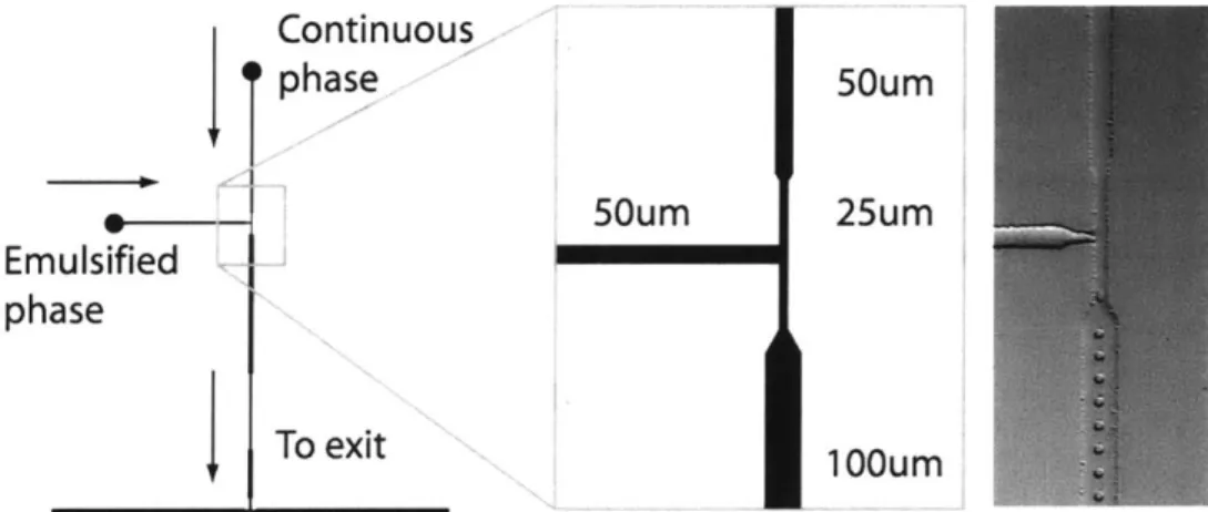
Continuous phase 50um 50um 25um Emulsified phase To exit 100um
Figure 2.2: Schematic of a Droplet Generating Nozzle used in Incubation Studies
Light mineral oil (-25.1 cSt) containing 4.5% Abil EM 90 surfactant (Degussa) by volume was chosen at the continuous phase to emulsify water. Pressurized reservoirs of
the fluids were connected to the device via 500pm inside diameter Tygon tubing
(apparatus details are provided in Appendix B). The pressure balance was set to generate a steady stream of droplets on the order of ~10 Hz. Exact pressure values and production rates were less important in the present experiments, as qualitative behavior and
incubation delays are evaluated to select optimal design strategies. The effect of driving pressure, operating fluid and microchannel dimensions on resulting fluid flow rates is reviewed.
2.4.1 Microchannel Resistance Relationships
To increase the travel time of emulsion streams through a device it is tempting to use very long microfluidic channels, however this is not a practical solution. The operating pressures required to drive fluids at the inputs become unreasonably large since the
effective fluid resistance of microchannels scales linearly with length. The effects of various geometric and hydrodynamic parameters on fluid retention time are briefly reviewed. A simple method to examine the effects of channel geometry on overall fluid velocity is desired.
As first approximations in microchannels, for a given fluid and pressure drop per unit length, the average flow rate scales with
Q
~ RHYd4 , and the average velocity scales withV RHyd2,where RHyd is the effective hydraulic radius49. The simple expression relating
volumetric flow rate of a Newtonian fluid through a microchannel due to a pressure differential follows from the Ohm's law electrical analogy5 0. The pressure difference
through a channel is equal to an average flow rate,
Q,
times the resistance of a channel,AP = QQ With:
AP = P - P.
Chapter 2 - Droplet-Based Assay Platform
32
32
Pi, and P0 ut are the pressures at the inlet and outlet of a channel of length L. The
Poiseuille fluidic resistance in circular channels filled with fluid of viscosity p may be defined by50' 5 1:
8Lu
In circular channels, the volumetric flow rate of fluid is the average velocity multiplied by the cross sectional flow area:
Q=VgR2
Several techniques have been developed for the calculation of the effective hydraulic resistance in rectangular microfluidic channels, of width w and height h, typical of those created by soft-lithography techniques 5. A series solution has been recommended5 1:
12pL h (192 1 nnrw
3 1 - 5 5tanh
wh3 W 7 n-1,3, na 2h
While in the limit of low aspect ratio rectangular channels (w ~1 Oh), a simpler approximation (of parallel plates) may be used which neglects the series terms51
:
12pL
wh3
In the design of microfluidic droplet incubation systems, we are interested in quickly analyzing the effects of geometric changes on hydraulic resistance through a series of iterations. The series solution is accurate for a wide range of channel aspect ratios, but effects of varying channel geometries not intuitive. Another approximation is
recommended, where the hydraulic radius term in the circular Poiseuille equation may be estimated as twice the cross sectional area divided by the wetted perimeter5 0:
R Hyd = wh w+h
An example calculation illustrates the effect of using these three different approaches to approximate hydraulic resistance in a microfluidic channel. The resistance of a 100 ptm wide, 1 cm long, water filled channel as a function height is presented in Figure 2.3.
1.OE+15
-U- R Series Solution
1.OE+14 -'+- R Hydraulc Radius
-0-- R LowAspect Ratio Approdmation
1.0E+13
1.0E+10
0 50 100 150 200 250 300
Height(um)
Figure 2.3: Resistance Calculations as a Function of Height in a 1 OfPm Wide Channel
Although the hydraulic resistance is slightly overestimated by the use of the hydraulic radius approximation, the values are in good agreement to those calculated by the more complicated series solution. The low aspect ratio assumption begins to diverge as the height is increase beyond 2h ~ w and is unreliable for comparing two or more channels which significantly differ in height. For the purpose of simplicity, the hydraulic radius approximation is used for investigating the effects of changes in channel dimensions on fluid flow rate.
The average velocity of a fluid particle through the channels is found by substituting the hydraulic resistance into the flow rate expression:
- APRd AP
(
wh 28Lp 8Lp w+h
The amount of time it takes a fluid particle to traverse the channel length is finally:
L 8L2p Pw+h 2
V ALP wh
The average time that it takes fluid to reach the outlet scales with the square of the length, and inversely with the square of the hydraulic radius. While very long channels may be fabricated, the operating pressures required to generate sufficient shear for emulsification become prohibitively large. At pressures greater than ~30-40 psig, the bond between the PDMS device and the coverslip is prone to failure. From experience, the tubing
connection ports to the inlets may separate from the device. Operating pressures in the range of 5 psig to 15 psig are preferred for these reasons.
An optimal solution should enable droplet production at high frequencies from the nozzle, yet retain droplets for long periods in the channels. This solution comes from a compromise between the channel hydraulic radius and overall length. Channels with non-uniform cross sectional areas were investigated.
2.4.2 Pancake Design
To reduce the flow rate of droplets through the device, large flat pads (or "pancakes") were tested first. The volumetric flow rate of the continuous phase would be hindered significantly by travel through a large open area. Support pillars were included in the design of the pancakes to prevent the large aspect ratio PDMS channels from sagging or collapsing48. The mask used to create the molds and photomicrograph of one such device is illustrated in Figure 2.4.
Chapter 2 - Droplet-Based Assay Platform
35
5mm flats
Figure 2.4: Pancake Style Incubation Chambers
This design proved to be very effective in hindering the rate of droplet flow through the flat. However, significant dispersion of droplet streams was evident. Figure 2.5 presents a series of micrographs taken at two minute intervals. Droplet flow through a 5 mm flat required ~ 15 minutes, operating at oil and water pressures of 12 psig and 10.4 psig respectively.
Figure 2.5: Emulsion Flow Dispersion within Pancake Incubation Chamber
Restricting the droplet flow from to wide channels did not seem to be a viable option. Although droplet flow was significantly delayed through the retention element, emulsion dispersion was problematic. A first-in-first-out order could not be guaranteed if large numbers of droplets collided with one another. In other cases, coalescence would occur as a result of colliding droplets, and the resulting emulsions would never be able to exit the chamber. Such design elements also require a significant area of the device footprint, and are not an efficient use of limited area available within a microfluidic device. It was
Chapter 2 - Droplet-Based Assay Platform
36
necessary to investigate the use of non planar design elements to increase droplet retention time.
2.4.3
Dome Design
This approach to droplet retention has been previously explored'3, although its initial success in delaying droplets for times of 1-4 hours suggested that this idea was worth revisiting and possibly refining. After standard lithography steps have been completed to create the underlying channel geometry, a large incubation chamber is created by adding a drop of photo resist to the wafer. The drop of photoresist is fixed to the mold by hard baking the wafer at 130'C for 30 minutes. Many different dome volumes were tested to investigate the effect on droplet behavior. Initially small large domes were manufactured in simple channel designs to test this concept. A device containing a 1mm diameter dome is illustrated in Figure 2.6.
Figure 2.6: A 1mm Droplet Incubation Dome
A droplet flow sequence through a small retention dome is presented in Figure 2.7. Interval times are noted. In small domes, the emulsion stream maintains a direct path from the entrance to the exit channel of the dome. In a single 1.5 mm dome, droplet delay was ~5 minutes operating at oil and water pressures of 20 psig and 12 psig respectively. At the same pressures, droplet retention increased more than -15 minutes in a 2.5 mm dome.
37
Figure 2.7: Droplet Flow through a 1mm Incubation Dome
Addition of multiple incubation domes is a simple step and may provide sufficient incubation time for in vitro protein synthesis. Figure 2.8 illustrates a possible layout employing many domes in serial.
Figure 2.8: Design Intent for Serial Domes
This design, however, is difficult to reproduce from one mold to another. In order to center the large domes with existing channel geometry, special masks were design which included a ring where a drop of AZ photoresist was to be deposited. The rings were intended to increase manufacturing consistency between individual domes when using the crude technique of applying the extra photoresist manually. Figure 2.9 illustrates the mask and pictures one of the resulting devices including four incubation domes.
38
tapered nozzle 1mm
Figure 2.9: Incubation Domes Implemented in Serial
The inline domes provided scalable and effective droplet retention through the
microfluidic channels, but there remained shortcomings of these manually manufactured design elements. Although photoresist could be deposited using a pipette into the rings, the high viscosity and surface tension of AZ 4620 did not allow small volumes to be metered easily. There was slight variability between domes in the actual microfluidic devices.
In order to increase droplet retention time, large domes (several millimeters in diameter) are required which lead to additional problems. When such a microfluidic device is tested, it could take over half an hour to purge all of the air from the chambers into the bulk PDMS. During this period, the pressure balance at the crossflow junction had to be continually monitored; otherwise a stream of the emulsified phase could flow directly into the channels. If large coagulations form inside of a dome, they are impossible to remove, and interfere with passing droplets. Clogs within 2.5 mm domes are pictured in
Figure 2.10. Shear levels within the large domes are significantly lower than those at the crossflow nozzle, and large emulsions may not be cleared. This problem was alleviated slightly by first backfilling the device with oil from the exit port, although complete priming of the channels before every experiment was time consuming.
Chapter 2 - Droplet-Based Assay Platform
39
Figure 2.10: Droplet Clogs in 2.5mm Incubation Domes
2.4.4 Circular Step
A new fabrication approach was tested to improve the repeatability of the dome chamber design. Three-dimensional molds for soft lithography have been prepared using multiple photolithography steps with SU-8 photoresist (Microchem) in order to create complex networks of microfluidic channels on multiple planar levels52. In contrast to the opaque-colored AZ 4620 photoresist, SU-8 is transparent, and allows for multiple features to be built up on a silicon wafers using repeated coating and exposure procedures. SU-8 is available in a range of grades, which allows extremely thick layers, up to -250 pm, to be created in a single lithography step. Fabrication details for the SU-8 soft-lithography molds designed in this section are provided as a reference in Appendix A.
The benefit of this fabrication technique was used to create microfluidic molds, allowing devices with repeatable designs to be developed and improve on the drawbacks
experienced with previous dome experiments. A base channel network is created in the first photolithography step, containing the essential nozzle geometry and flow network. Before the base design is developed, an additional layer of photoresist is spun coat onto the existing features. The droplet incubation chambers are then aligned with existing
features and the new layer of photoresist is developed. This process may be repeated as many times as required to build non-planar patterns.
SU-8 is a very durable photoresist, and results in features with nearly vertical side walls. Although mold profiles created with AZ photoresist are typically rounded to prevent the aggregation of small spherical droplets along the walls12, this did not appear to be problematic in these smooth rectangular channels.
Masks with a stepped circular chamber where designed and tested. Figure 2.11 illustrates the two masks required, to perform the two step lithography process. SU-8 is a negative photoresist, so UV exposure through clear areas of the masks is used to cross-link the resist and solidify the feature patterns. As such, the majority of the mask is opaque, and alignment grids are located on the corners of the masks to simplify alignment of design features during photolithography.
Figure 2.11: Masks to Fabricate SU-8 Incubation Domes
This design was fabricated with a 15 pm base layer, with a 100 ptm second layer patterned on top to create the droplet incubation chamber. The droplet flow pattern through a 3 mm diameter chamber is pictured at three different times in Figure 2.12.
41
- - I. ~ - .- - --- - -
-Figure 2.12: Droplet Flow through the Circular Step
Droplet retention was very effective using this microfabricated pad. Through a 3 mm diameter circular pad, droplets were retained for more than 7 minutes, with oil and water pressures of 10 psig and 8 psig respectively. The droplets maintained a relatively regular order through the centerline of the circular element, and did not demonstrate the
significant dispersion problems experienced with the pancake design. The use of non-planar elements improves coherence of a single line of droplets, and provides excellent retention. However, the circular pads require a significant area of the device footprint
compared to the otherwise fine channels. As the droplet flow streamlines remain near the center of the circular step, it is indicative that the additional oil in the chamber does not play an important role in the fluid flow and the excessive area of the chamber may not be required to provide retention. The idea of compact, inline microfabricated steps was
explored next to test this hypothesis.
2.4.5 Inline Step
Compact and scalable droplet incubation elements evolved into direct multi-height channels. Inline steps molds were fabricated with chamber widths identical to those 100 ptm wide on the base layer. Base channel heights were 15 ptm, with 100 pm tall
chambers aligned on top to provide a total chamber height of 115 pm. Figure 2.13 illustrates the masks used in the two-step lithography process, with chamber lengths noted.
Chapter 2 - Droplet-Based Assay Platform
42
Figure 2.13: Masks for an Inline Step
Figure 2.14 illustrates an inline step, with channels of identical widths but of two different heights.
Figure 2.14: Calculation of Droplet Flow Rate
Chapter 2 - Droplet-Based Assay Platform
43
The flow rate of water droplets is not the same as the flow rate of the continuous phase through the channels. Conservation of mass for the incompressible oil tested implies that fluid velocity through the "high" channels scales inversely with ratio of the channel areas.
Q=V A base = V,, Astep =const.
or
A
step = base Astep
base
With constant channel widths, the area ratio reduces to a ratio of base to step heights only.
Vstep = Vase
155
= 0.13VaseNominally, the fluid in the base channels is moving approximately 7.7 times slower in the stepped section. By video inspection, the reduction factor in droplet velocities was
approximately 4 in the same channels.
There were two factors are responsible for this difference. Firstly, the pressure-driven laminar velocity field of the continuous oil phase in the channels follows the well-known Hagen-Poiseuille parabolic distribution, with no-slip boundary conditions at the walls and maximum velocity occurring at the center of the channel. While the size of the droplets (-10 pm) would constrict their flow to the center of the base level channels, they are unconfined in the stepped sections. If the droplets are allowed to stray from the
centerline of channels in the tall sections, they would slow down. Fluid drag on droplets also plays an important role. While droplet plugs (droplets that are large enough to conform to the cross sectional area of the channel) move at approximately the same velocity as the continuous phase26, the small, spherical droplets generated in these channels are expected to be moving much slower due to drag. Although recirculation within viscous droplets due to external surface shear reduces the Stoke's drag on
Chapter 2 - Droplet-Based Assay Platform
44