All-Optical Pulse Regeneration in a Faraday
Stabilized Ultrafast Nonlinear Interferometer
by
Shelby Jay Savage
Submitted to the Department of Electrical Engineering and Computer
Science
in partial fulfillment of the requirements for the degree of
Master of Engineering in Electrical Engineering and Computer Science
at the
MASSACHUSETTS INSTITUTE OF TECHNOLOGY
May 2001 [>©
Shelby Jay Savage, MMI. All rights reserved.
BARKEfj
The author hereby grants to MIT permission to reproduce and
distribute publicly paper and electronic copies of this thesis document
MASSACHUSETTS INSTITUTE
in whole or in part.
OF TECHNOLOGYJUL 11 2001
LIBRARIES
A uthor ... ... ... ... # . . . . .
Department of Electrical Engineering and Computer Science
May 23, 2001
C ertified by ... c-
...
Erich P. Ippen
Professor
Thesis Supervisor
Certified by... ...Scott A. Hamilton
MF Lincoln Laberatory Staff Member
Tesj.'Supervisor
Accepted by ...
Arthur C. Smith
-All-Optical Pulse Regeneration in a Faraday Stabilized
Ultrafast Nonlinear Interferometer
by
Shelby Jay Savage
Submitted to the Department of Electrical Engineering and Computer Science on May 23, 2001, in partial fulfillment of the
requirements for the degree of
Master of Engineering in Electrical Engineering and Computer Science
Abstract
Modern fiber optic communications networks multiplex data onto many different channels, each with its own carrier frequency. In order to meet rising demand for high data rates, researchers have begun to consider methods to use the bandwidth of optical fibers more efficiently. In particular, more efficient use might come from operating fewer channels with each channel at a higher data rate, or perhaps even, ultimately, from operating one ultrafast time division multiplexed channel. High data rate optical channels already surpass the limits of electronic processing, which today cannot handle rates greater than 40 Gbit/s. Researchers must design the individual hardware elements, like address recognizers, demultiplexers, and regenerators, that will be necessary for any practical system. One promising idea is to make these
devices all-optical. Already all-optical logical switching has been demonstrated at
100 Gbit/s and all-optical demultiplexing at hundreds of Gbit/s. But, in any long
haul system, it is also necessary to develop optical pulse regenerators to regenerate data encoded as optical pulses before those pulses become too distorted to detect. This thesis investigates an all-optical pulse regenerator that reshapes, retimes, and amplifies optical data pulses. A Faraday polarization rotator mirror is used to make it much more polarization stable than other designs. The physical principle on which it is based, the nonlinear index of refraction, is a nearly instantaneous effect and, therefore, does not suffer from the speed limitations of modern electronics. We test the design for its switching window, bit error rates, and sensitivity to timing jitter to show its usefulness as an optical pulse regenerator.
Thesis Supervisor: Erich P. Ippen Title: Professor
Thesis Supervisor: Scott A. Hamilton
Acknowledgments
The acknowledgments section is the writer's chance to expand the list of "authors" to its more realistic length. This thesis is the labor of many people, not just of those engineers directly involved in its composition, but of those who gave me their encour-agement and friendship during my work on it. This section is the most important single section of this thesis, and it is my honor, among all those "authors," to write it.
My first thanks go to everyone at MIT Lincoln Laboratory. My thesis advisor,
Professor Erich Ippen, knows that true understanding comes from comprehension of fundamental concepts, and I thank him for always explaining physics to me with that fact in mind. He has only spoken kindly and patiently to me and has helped me see to the end of some of my most challenging technical problems. My supervisor, Scott A. Hamilton, has always dealt with me gently and patiently. Many days, he spent more time with my work than with his. I thank him for his encouragement, his thorough notes on all my writing, and, most of all, for introducing me to downhill skiing. A student at Lincoln Laboratory, Bryan S. Robinson, taught me, more than anyone else, how to use the equipment in D-409. Without him, I would be, in this moment, answering for hundreds of thousands of dollars of broken hardware rather than submitting this thesis. His knowledge of laboratory methods, his technical imagination, and his doggedness with every idea and every piece of equipment have been the primary reasons that this work has gone as far as it has. Peg Danek has been great help in the laboratory and has given me (or sometimes I might say cursed me with) the knowledge of splicing optical fibers. Thanks as well, to Tom Murphy, who is always ready to answer a question; to Steve Constantine, whose many mortgages have been a source of amusement to me on my worst days, and whose encouragement has always propelled me on; to Sam Wong for suffering along side me; and to Todd Ulmer for expanding my musical horizons.
A large share of credit for the completion of this thesis also belongs to those
who reminded me unceasingly that life is more than ultrashort optical pulses and all-optical fiber switches. An aquaintance from California once told me that MIT is a better place to be from than to be at. I owe thanks, however, to my friends at MIT for making MIT just as wonderful a place to be at as it is a wonderful place to be from. My apartment mates, Barb Huppe, Jon Wong, Serena Chan, and Abe McAllister, made me enjoy the little time I had from work and responsibility with games, conversation, and frisbee. It is largely to them that I now owe my subtle understanding of world conquest. My thanks go to Allison Waingold, who has been my friend almost from the beginning of my time at MIT and who endured several terms of Friday night study sessions and a full semester of number theory with me. I also must thank Garrett Cradduck, who caused my first all-nighter at MIT, who shares with me an insatiable passion for numbers and music, who taught me the beautiful gentle strains of "Danny Boy," and who, like me, appreciates undeep edifying poetry. Denise and Paulo Oliveira have filled those parts of my academic interests that lie outside the norm of MIT, and I thank these two friends of mine for bringing some
humanity to a very mechanical campus. Christina Silcox is able to appreciate both the academic and the joyful in life. I thank her for being the most frank of all my friends and for helping me to live life. My thanks also go to Brian Purville, Olu Fashoyin, Danielle Ayodele Hinton and Bapu Jena, my fellows of West Campus. I give special thanks to Michele Micheletti, whom I knew for my first three semesters at MIT, and who was among my first friends. On Halloween night of 1997, she was struck by a car while we crossed Memorial Drive. We bear your memory with us.
The group that made MIT endurable more than any other was the Protestant Student Community. In my personal quest to identify once and for all the nature of Christ's Church on earth, I have only discovered one thing: we are occasionally blessed to find a community in which we unmistakably feel Christ's charity moving gently and tenderly, a part of that Church of Pentecostal Fire. I found it in the Protestant Student Community. Chaplain John Wuestneck has always been my good friend and has brought me new ideas in my growing knowledge of Christianity. John Mckay and Jamie Byrum brought me as fully into their lives as anyone can and shared with me the toils and vicissitudes of life as well as its triumphs. They truly believe, each in his own way, in the life found in Christ and give me hope for our Church. I thank them for being the sort of friends whom a man knows will hang with him in every kind of trial. I also thank Lora Reineck, who joined me in tutoring at the 4th Presbyterian, who brought me into MIT Concert Choir, and who, somehow, challenges me to be better than I could otherwise be. I am proud to be her friend. My thanks go to James Taylor, truly one of the kindest people I know. Jason Andrews and Vicki Schubert have kept me on the straight and narrow in bible study and always give me faith. I offer thanks to my other friends in PSComm: Annika Hill (who has hit me more than any other person on earth), Susanna Mireau, Mark Ethier, Katie Knopp, Lynn Maria Matthew, Onsi Fakhouri, Jack Williard, David Milovich-for their fellowship.
I owe an unpayable debt to my father, my mother, and my brother. My father is an engineer himself, and his help from the beginning has kept me from discouragement and from giving up. I thank him for his unlimited patience, which bore even my sometimes caustic and sarcastic personality. My mother is devoted to her sons. She volunteered at our elementary school, pushed us to succeed, and gave us everything we needed and, sometimes, more than we wanted. My parents were born to lives poorer than almost any American must endure today and are models to which I can only hope to rise. My brother, one year younger than I am, has been my only lifelong friend and peer. I thank him for encouraging me, even while I have been away from home.
Contents
1 Introduction
2 Physics of All-Optical Switching
2.1 The Intensity-Dependent Index of Refraction . . . . 2.2 Examples of All-Optical Switches . . . . 2.2.1 The Nonlinear Mach-Zehnder Interferometer . . . . 2.2.2 The Ultrafast Nonlinear Interferometer (UNI) . . . .
2.3 Relevant Physical Properties . . . .
2.3.1 D ispersion . . . .
2.3.2 The Nonlinear Schrddinger Equation . . . .
2.3.3 Effects of Loss and Pulse Envelope Shape on Phase Shift
3 Previous Work in All-Optical Switching
3.1 The Nonlinear Optical Loop Mirror . . . .
3.1.1 The NOLM as a 2R regenerator . . . .
3.1.2 The NOLM as a 3R Regenerator . . . .
3.2 Semiconductor Laser Amplifier in a Loop Mirror (SLALOM) . . . . . 3.3 Considerations Specific to Regeneration and Problems with Loop
Mir-ror Sw itches . . . . 4 Characterization of Fiber as a Nonlinear Medium
4.1 Dispersion and Walk-off . . . . 4.2 Measurement of the Nonlinear Index of Refraction . . . .
13 16 . . . 16 . . . 23 . . . 23 . . . 26 . . . 28 . . . 28 . . . 32 . . . 37 41 42 43 45 52 57 60 60 66
4.2.1 4.2.2 4.2.3
Effects of Self-phase Modulation . . . . Numerical Solution to the NLS . . . . Experimental Measurement of -y . . . . 5 Design and Testing of the Folded UNI
5.1 The Folded UNI ...
5.2 Experimental Setup ...
5.3 FUNI Switching Window . . . .
5.4 FUNI Regenerator Error Performance .
5.5 Sensitivity to Timing Jitter . . . . 5.6 Regenerative XOR . . . . 6 Conclusions and Future Work
A Split-Step Fourier Code
67 70 75 81 . . . . 82 . . . . 84 . . . . 85 . . . . 89 . . . . 91 . . . . 93 97 101
List of Figures
2-1 Nonlinear Mach-Zehnder interferometer. . . . . 23
2-2 Normalized output intensity of the nonlinear Mach-Zehnder
interfer-om eter versus <Irel. . . . . 25
2-3 The Ultrafast Nonlinear Interferometer (UNI) separates the signal pulse
into orthogonal components. The control pulse induces a phase shift in one component; both components are then interfered at PZR2. The components are polarization controllers 1, 2, and 3 (PC1, PC2, and
PC3), polarizers 1 and 2 (PZR1 and PZR2), birefringent fiber (BRF),
semiconductor optical amplifier (SOA), and band pass filter (BPF). . 27
2-4 Dispersion induced broadening of a Gaussian pulse in an optical fiber. 32 2-5 Output pulse contrasted with input signal pulse after passing through
a nonlinear Mach-Zehnder interferometer with YA2L =..r . . . . 39
3-1 The linear optical loop mirror. . . . . 43
3-2 The self-switch (left) and the plot of input power verses output power of an ideal self-switch (right). . . . . 44
3-3 The nonlinear optical loop mirror with control pulses adding an
imbal-ance between CW and CCW pulse streams for 3R all-optical regeneration. 46 3-4 Walk-off of a data pulse through a clock pulse. Timing jitter in the
data pulse makes the time at which it is coupled onto the NOLM, relative to the clock pulse, unpredictable. . . . . 47
3-5 NOLM switching window for 2.5 ps FWHM clock and data pulses with
3-6 NOLM switching window for 2.5 ps FWHM clock and data pulses with
8 ps of relative walk-off . ... ... 51
3-7 In the SLALOM, the imbalance between clockwise and counter
clock-wise propagating clock pulses is provided by an SOA set off-center in the loop. The DSF is dispersion shifted fiber and the PC is a polariza-tion controller. . . . . 53
3-8 SOA gain saturation due to the arrival of a short intense pulse at 10
ps. The recovery constant re is on the order of 100 ps and the small signal gain is 100. . . . . 56 3-9 SLALOM with control pulses that saturate the SOA. This design can
be applied as a regenerator by replacing the control pulses with data pulses. In order to maximize switch efficiency, CP1 is a 50/50 coupler and CP2 is a wavelength dependent coupler. . . . . 56
4-1 Experimental setup to measure group delay as a function of carrier frequency. MZM is a Mach-Zehnder modulator and EDFA is an erbium doped fiber am plifier. . . . . 63
4-2 Plot of relative group delay of sine wave modulation versus the wave-length of the carrier for the 500 m spool of DSF used in this thesis. The curve is a least squared error parabolic fit . . . . 63
4-3 Plot of relative group delay of sine wave modulation versus the wave-length of the carrier for the 2,000 m spool of DSF used in this thesis. The curve is a least squared error parabolic fit . . . . 64 4-4 Plot of relative group delay of sine wave modulation versus the
wave-length of the carrier for the 4,000 m spool of DSF used in this thesis. The curve is a least squared error parabolic fit . . . . 65
4-5 The top plot shows the phase shift induced by SPM on a Gaussian pulse and on a super-Gaussian pulse of order 3. The bottom plot shows the frequency chirp of the same pulses. Both plots are in normalized units. 69
4-6 Calculated spectra of an SPM-broadened pure Gaussian pulse. The spectra are labeled by the phase shift induced at the peak of the pulse. Notice the difference in scale of the top three and bottom three plots. 70
4-7 The split-step Fourier method of solutions involves alternate applica-tions of the linear and nonlinear operators. Linear steps are labeled with an "L" and nonlinear steps are labeled with "NL." The axis shown is the discretized spatial axis. . . . . 73
4-8 Spectrum of a 2.5 ps intensity FWHM Gaussian pulse with .565 W peak intensity after propagating 3135 m in dispersionless optical fiber.
y is set at 0.002 m-'W-1. With those parameters, the phase shift
acquired at the peak of the pulse is 1.57r. Therefore, the trough is at its m inim um . . . . . 74 4-9 Spectrum of a pulse with the same parameters as described in
Fig-ure 4-8, except 02 = -20 ps2/km. Notice the difference caused by the
nonzero dispersion. . . . . 75
4-10 Experimental setup for measuring -y. EDFA stands for erbium doped fiber amplifier, and the source generates 2 ps Gaussian pulses at 10 GHz. 78 4-11 Spectra of pulse propagation at the end of a 500 m DSF spool for
various peak powers. The inset shows a boxed area of the plot for detail. 79
5-1 In the folded UNI, a Faraday mirror provides polarization stabilization. PC1 and PC2 are polarization controllers, PBS is a polarizing beam
splitter, DSF is dispersion shifted fiber, BPF is a band pass filter, BRF is birefringent fiber, FM is a Faraday mirror, and EDFA is an erbium doped fiber am plifier. . . . . 82
5-2 Experimental setup to test the Folded UNI as an all-optical regen-erator. Solid lines represent optical paths and dotted lines represent electrical paths. EDFA stans for erbium doped fiber amplifier, BPF for band pass filter, EOM for electro-optic modulator, FM for Faraday mirror, PBS for polarizing beam splitter, BRF for birefringent fiber,
DSF for dispersion shifted fiber, MLFL for mode-locked fiber laser, and
DPLL for dithering phase-locked loop. . . . . 86 5-3 Autocorrelation trace of a 1.9 ps pulse from a PriTel laser source
op-erating at 10 GHz. . . . . 87
5-4 Block diagram of experimental setup for taking a switching window. The control and signal pulse trains are at slightly different pulse rates to cause a walk-off that varies with time. The switching window appears on the sampling oscilloscope. . . . . 88 5-5 Switching window of the folded UNI with the 500 m spool of fiber,
with the signal pulses at 1550 nm, and with the control pulses at 1545 nm . . . . 89 5-6 The receiver used to test the bit error rate of the folded UNI as a
function of receiver input power. The EDFA is an erbium doped fiber amplifier and the PD is a photodiode. . . . . 90 5-7 Bit error rate test of folded UNI with the 500 m spool compared to a
baseline test. The signal carrier wavelength is 1556 nm and the control carrier wavelength is 1545 nm. . . . . 91 5-8 Setup for testing the tolerance of the folded UNI to timing jitter. The
data pulses are amplified by an erbium doped fiber amplifier (EDFA),
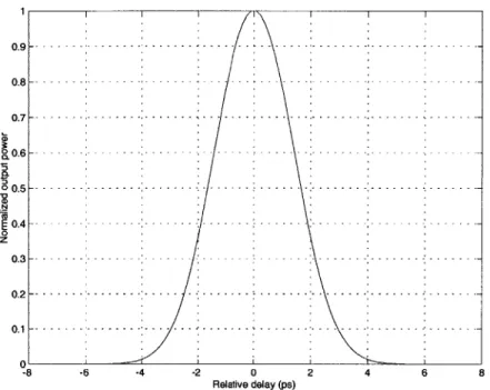
and a single RF synthesizer drives both mode-locked fiber lasers. . . . 92 5-9 The bit error rate of the folded UNI as a function of the relative delay
between data pulses and clock pulses. . . . . 93
5-10 The folded UNI as it is applied to regenerative XOR. . . . . 94
5-12 The top plot shows the photodiode output of channel A after
regen-eration in the FUNI. The middle shows the same for channel B. The bottom plot shows the regerated XOR of A and B. All voltages are normalized. A and B are at 10 Gbit/s. . . . . 95 5-13 Photodiode outputs of regenerated A and B and of the regerated XOR
List of Tables
Chapter 1
Introduction
Optical fibers provide most of the bandwidth available in long distance communica-tions systems. Researchers continue to seek new ways to use all the available low loss sections of the optical fiber bandwidth, exceeding 25 THz [1]. It is not enough, however, to demonstrate propagation of optical signals using this bandwidth. At such high data rates, networks must be able to process these signals for tasks like address recognition before any such system can become practical. Many researchers forsee the use of optical time division multiplexing (OTDM) in high data rate systems. In OTDM systems, signals are digitally encoded as short optical pulses, perhaps shorter than a picosecond, and different data channels are interleaved in time [2]. The many tasks required in a high data rate TDM system include time multiplexing and demul-tiplexing of data [3], wavelength conversion [4], ultrafast data encryption [5], address recognition [6], and clock recovery [7]. Unfortunately, electronics are limited today to about 40 Gbit/s and cannot process the billions or trillions of bits per second in such an OTDM system. Researchers are, however, investigating alternatives that forego the conversion of the optical signal to electronic data. Instead, photonic data are pro-cessed using ultrafast all-optical techniques. This thesis studies a design for all-optical pulse regeneration, a problem that has received much attention in the last decade. Pulses that propagate long distances acquire unwanted distortions that make them difficult or impossible to detect. Any long-haul system will require periodic pulse regeneration, and the most efficient and cost-effective solution may be optical rather
than electronic [8].
A number of ideas for all-optical regenerators have been demonstrated (for
ex-ample, see [9, 10, 11]). Many of these designs use an intensity dependent index of refraction to achieve an optically controlled nonlinear phase shift. An important design choice is the nonlinear waveguide medium. Some designs, like the nonlinear optical loop mirror [12], use optical fiber as the onlinear medium; others, like the ultrafast nonlinear interferometer (UNI) [13] and the semiconductor laser amplifier in a loop mirror (SLALOM) [14], use a semiconductor optical amplifier (SOA). The
SOA has a very high nonlinear index of refraction, which makes it possible to use
short (~1 mm) devices and low optical pulse powers. This advantage is important in optical logic, where low latency switching is often necessary for a successful de-sign. The UNI has already been shown to switch pulses at 100 Gbit/s in all-optical logic [13]. SOA's have a gain recovery time that is long compared to the nearly in-stantaneous effects of the nonlinear index of refraction in optical fiber. This recovery time can cause amplitude patterning in the output of the switch. Pulse patterning is an important obstacle to overcome in switch design [15]. One possible solution to the problem of pulse patterning is pulse position modulation (PPM) [16]. Optical fiber, on the other hand, provides an ultrafast nonlinear index and a nearly lossless transmission medium. The nonlinear index in fiber, however, is relatively small and longer lengths (~km) must be used to induce the necessary phase shift. This length can cause unwanted distortions in the pulses as they propagate down the fiber [17]. For long-haul short optical pulse transmission, PPM may be undesirable due to its increased sensitivity to timing jitter compared with on-off key data. For regeneration, however, low latency switching is not required, and optical fiber based switches can be used. The distortions that accompany long propagation in fibers can be reduced
by using low dispersion fibers like dispersion shifted fiber. Thus, in the application
of regeneration, optical fiber is an important alternative to semiconductor optical amplifiers.
Several regenerator designs use fiber as the nonlinear medium [18]. The UNI itself can be adapted to fiber. This thesis investigates an all-fiber variation we call
the folded UNI. In this thesis we also present the results of switching experiments in the folded UNI and demonstrate this device as an all-optical regenerator. The folded UNI's advantage is its inherent polarization stability. The UNI, as mentioned above, has been shown to perform well as an all-optical switch. But, temperature variations and other slow changes in the fiber can cause the polarization to drift. After a length of time on the order of 30 minutes the polarization of the pulses in the UNI must be adjusted. The design of the folded UNI makes it unnecessary to control the polarization of pulses already in the switch.
Chapter 2 presents the nonlinear Schrddinger equation and the basic theory needed to understand optical pulse propagation in fiber, which includes dispersion and the nonlinear index of refraction. In Chapter 2 we also introduce two examples of all-optical switches, which are useful for all-optical pulse regeneration.
Chapter 3 reviews previous work in all-optical switching, specifically, the NOLM and the SLALOM. Chapter 3 also lists some important qualities of a good regener-ator design and summarizes the disadvantages of the NOLM and the SLALOM in regeneration.
Chapter 4 uses much of the theory developed in Chapter 2 to show how one can measure the dispersion and nonlinear index of refraction of optical fiber. Both of these parameters are important in choosing fiber for the folded UNI regenerator design. This chapter also presents a numerical model to simulate pulse propagation in fiber.
Chapter 5 introduces the design of the folded UNI and gives the experimental setup used to test the folded UNI. The chapter presents data on the switching window, which is important in showing the ability of the folded UNI to correct timing jitter in an incoming network data stream that is to be regenerated. In Section 5.4 we discuss the results of a bit error rate test on the folded UNI. Finally, Chapter 5 presents results on the folded UNI's application to a regenerative XOR all-optical logic gate.
Chapter 2
Physics of All-Optical Switching
The all-optical switches presented in this thesis are various types of fiber interfer-ometers. This chapter intoduces the physical principles that describe the behavior of these fiber interferometer switches. The first section of this chapter introduces the intensity-dependent index of refraction, the physical principle on which most all-optical switches and many all-all-optical regenerators are based. The intensity-dependent index of refraction can induce a phase shift in an optical pulse. From this simple principle, one can create a fiber interferometer. The second section of this chapter describes a fiber switch, the ultrafast nonlinear interferometer (UNI). The final sec-tions introduce the important physical properties of fiber and of the various nonlinear media that are relevant to the problem of all-optical regeneration.
2.1
The Intensity-Dependent Index of Refraction
The intensity-dependent index of refraction is given by
n = no
+
n2l (2.1)where no is the linear index, n2 is the nonlinear index, and I is the intensity of
the electric field envelope. This intensity-dependent index is a consequence of the nonlinear interaction of the optical field with the medium of propagation. More
specifically, in SI units, we have
D(r, t) = EoE(r, t) + P(r, t) (2.2)
where D is the electric displacement, E is the electric field, and EO is the permittivity
of free space. The nonlinear effects are included in P:
P(r, t) = EOX E(r, t) + PNL(r, t). (2.3)
X), the linear susceptibility, is a matrix that describes propagation for low optical
intensities. PNL is the nonlinear polarization
PNL(r, t) = EofX(2) :EE + X(3EEE + (2.4)
= P(2)(r, t) + P 3 (r, t) + -
--where x(') is the second order susceptibility and X( is the third order susceptibility. They are second and third order tensors respectively. Notice that Equations 2.3 and 2.4 express each of the cartesian components of P(r, t) as a multivariable Taylor series expansion in the three cartesian components of E(r, t), where the constant term of that expansion is zero [19]. That is, P(r, t) is a nearly arbitrary function of E(r, t) where P = 0 if E = 0. Assuming the pulses are propagating down a one-dimensional
wave guide in the z direction, r becomes simply z. To do these calculations, we now assume that we can expand E(z, t) in a Fourier series as
E (z, t) = ENt(w,,) e'(0n- W"t) (2.5)
n
In Equation 2.5, we have assumed that the waves are propagating in the z direction down a waveguide. We also expand the polarization in a Fourier series to get
P(b) (r, t) = P (b)(n)e-iWnt (2.6) n
where the r dependence of P(b) has been supressed for notational convenience. Be-cause E and P are real,
E(n)
= E*(--n) and P(b)(W') = P(b)*(-o) The ithcomponent of f(2) is given by
p()(~Wn
) =jZ(n
(+ Win; Wn, Wm)Eij(Wn)Ek(wm) e(3 +8m (2.7)jk (nm)
where i,
j,
and k can be any of the cartesian components of the field, x, y, andz. Ej(Wn) is the
j
vector component of E(Wn) of Equation 2.5. The notation (nm)requires that the sum be performed over Wn and wm such that Wm + Wn remains at a fixed value no matter the values of Wn and Wm. More generally, the expression for
P(b) is given by
A.(b)( + m+.)ZZx .. (nw + ;w w,+
jk- (nm -) (28)
k..( m..)[5j (Wn)5Ek (Wm) -..-. ei(On+Om+---)Z.(28
For a more thorough and similar description of the nonlinear polarization, see [20]. Now we show how the nonlinear polarization yields the intensity dependent index of refraction. We assume a medium where the only significant susceptibilities are X(I) and X(). This assumption is reasonable in the silica glass of optical fibers, where X(2
is zero because of the amorphous nature of SiO2. To begin, we consider the problem of
two interacting plane waves at different optical frequencies. We simplify the problem
by first assuming that the fields are copolarized along the x axis:
E,(z, t) =
E(wi)ei""
+ c.c. with E(wi) = ,Ex(wi)elz (2.9)E2(z, t) =
N(w
2)e-i2t + c.c. with E(w2) = E,x(w 2)e 02z (2.10)where c.c. denotes the complex conjugate, and w, and w2 are parameters for
E
ratherthan variables on which
E
is functionally dependent. We assume that E1 is muchEquation 2.2 becomes, in the Fourier domain,
D(z, w) = coE(z, w) + P(z, w) (2.11)
We would like to calculate the effect of the pump on the probe. Thus, we are interested
in calculating P(3) (w2), which is the nonlinear polarization of the component of
b
atfrequency w2. The ith component of P(3)(w) is given by
P.M (3)
P3 (W Wn +Wm +Wr)Z Xikl (w + Wm + Wr;Wn wm7 wr)
jkl (nmr) (2.12)
E(wa) Ek (Wm)EI (wr jeian+m+pr )z.
If we substitute in w2 for Wn + Wm + Wr we can calculate P(3)(w2):
jkl (nmr) (2.13)
nE (Wn)Ek (Wm)EI (wr)e i(n+,.+r)z(
Four facts help us evaluate Equation 2.13.
1. The sum over (nmr) is covered in only six cases, assuming that w, # w2. For
example, wn = W2, Wm = wi, and Wr = -w 2. The other 5 cases are just the other
possible distinct assignments of ±Wi,2 to Wn,m,r that still yield Wn+Wm+wr =
W2-2. Because the E of Equation W2-2.5 is real, E(-wi) must equal E*(wi). Thus,
E(w)E(-wi) equals JE(wi)12.
3. Because silica is an isotropic medium, X3) must be zero if the indices, ijkl, take
on values that repeat an odd number of times. For example, X(3yy = X 0
becuase in the first case x and y are repeated an odd number of times, and in the second x and z are repeated an odd number of times. If, for example,
XiyY 0 0, then a field in the +y direction would create a response in the
+x direction. But the symmetry of an isotropic medium implies that there is no reason there should be a response in the +x direction rather than the -x
direction. Moreover, because both E1 and E2 are polarized on the x axis, the
sum over jkl in Equation 2.13 is nonzero only when
jkl
are all x. Therefore, we are concerned only with x,.W which is nonzero only when i = x. So, the(3) . (3)
only relevant nonzero Xijkl is XxxxX, and, for simplicity, we drop the subscripts.
4. The intrinsic permutation property states that X
(WnAWm+wr;wn,wm,wr)
=Xi (n + Wr + Wm; Wn, Wr, W). This equation is true because the names of the
subscripts themselves are arbitrary and, therefore, interchangeable, although Equation 2.13 implies that a change in the order of w's requires a corresponding change in the order of the subscripts of X
These four points imply that all X(3) tensor values relevant to this problem have the subscripts xxxx and have some ordering of wi, -wi, and w2, and thus are all
equal. Therefore, we drop all subscripts and arguments of x(3) to obtain
PNL(w2) = (iP ) = i6coX(
i(w2)
3) Ix(wl) 2 (w2)e 52 Z (2.14)
where k3 is defined in Equations 2.9 and 2.10. Substituting Equation 2.3 into Equa-tion 2.2 and taking it into the Fourier domain, we have
D(r, w) = coE(r, w) + -EOX() (r, w) + PNL(r, w). (2.15)
We are interested in the component of the field at the probe frequency w2 so we consider Equation 2.15 only at w2:
D(r, w2) = foE(r, w2) + EOj() -E(r, W2) + PNL (r, w2). (2.16)
We substitute Equation 2.14 and the positive frequency component of Equation 2.10 into equation 2.16. All of the vectors are nonzero only for their x components, so we drop the vector notation
In Equation 2.17, f(w 2) depends on both the pump field at carrier frequency w, and
the probe field at carrier frequency w2. We can rewrite Equation 2.17 as D(z,w2) = EO(1 + X()+ 6X(3)I5x(w1)12)Ex(w2)e02z = Eef fx(W 2)xe02z
where
6
efI = co(1 + X(1) + 6X (3)|E(wi)1 2).
(2.18)
(2.19)
By the definition of the index of refraction, we have n2
= C2 PiEeff. In a nonmagnetic
medium, this equation reduces to
n2 =ef f
Co (2.20)
In Equation 2.18, we see that IEx(wi) 12 implies an intensity-dependent refractive
index. By Equation 2.9, the pump wave is given by El(z, t) = i [x(wi)e(01z-''1t)+c.c.]
so that the time averaged electric field intensity is given by
(IE1(z, t)12) = 25&(wi)5*(wi) = 2I5x(wi)12. (2.21)
Thus, assuming a linear relationship between the index of refraction and the electric field intensity, we have
n = no + 2n2IEk(wI)12. (2.22)
We substitute Equations 2.22 and 2.19 into Equation 2.20 to get
[no + 2n2I x(wi)12]2 = 1 + X (1) + 6X ( 3)Ex(w
1)12. (2.23)
The left side of Equation 2.23 equals
no + 4non2lE(wi) 2
where we assume that n2 «no. If we substitute the approximation of Equation 2.24
into Equation 2.23, then we have
n2 + 4non2IEx(Wi)12 = 1 + X
)+
6X(35(01)1
2. (2.25)From Equation 2.25, we find that
no=
1 + xG)(W2) (2.26)and that
n2 = () . (2.27)
2no
Remember, that in this derivation it was assumed that the pump was much more intense than the probe. Therefore, the effect of the pump on the index of refraction seen by the probe was much more significant than the effect of the probe on the same index of refraction. This change in index of refraction changed the optical path length for the probe, in effect adding a phase shift to the probe. The case we studied in this section demonstrated the phase shift induced on a probe by a very intense pump. This effect, where a signal of one carrier frequency induces a phase shift in a signal of a different carrier frequency is called cross-phase modulation (XPM) [21]. Nonetheless, a probe signal, even in the absense of a pump signal, can induce a phase shift in itself. This effect is called self-phase modulation (SPM). In this thesis, we shall limit our discussion to the case of an intense pump with a probe too weak to induce a noticeable phase shift in itself.
Control
Signal Out Nonlinear Medium
Signal In Linear Medium
Figure 2-1: Nonlinear Mach-Zehnder interferometer.
2.2
Examples of All-Optical Switches
2.2.1
The Nonlinear Mach-Zehnder Interferometer
The nonlinear index of refraction has been used in a number of optical interferome-ters, including the nonlinear optical loop mirror (NOLM) and the ultrafast nonlinear interferometer (UNI). Before describing the operation of the UNI in Section 2.2.2, we first consider the simple Mach-Zehnder interferometer (see Figure 2-1). In the non-linear Mach-Zehnder interferometer the incoming signal pulses are split by a 50/50 splitter into two paths. One path is purely linear and nondispersive (for example, it could simply be free space). The other path contains a nonlinear medium, perhaps an optical fiber, which has an intensity-dependent index of refraction. Suppose that the signal pulses have a carrier wavelength of A0. Also, let L, be the length of the linear
medium and let L,1 be the length of the nonlinear medium. If the lower path contains
only linear material with an index of refraction equal to ni, then the linear medium's optical path length is nL1. The upper path contains a nonlinear medium, and its
index of refraction is given by nr' + n2'c, where n"' is the linear index of refraction,
n2 is the nonlinear index of refraction, and I is the intensity of the control pulse
that temporally overlaps the signal pulse. The optical path length of the nonlinear medium is (no' + n21c)Lna.
pulses in the two arms of the interferometer. Taking the difference of the two optical path lengths, we have
n'Li - (nn' + n2Ic)Lni. (2.28)
Dividing by Ao/27r gives us the relative phase shift:
(Prei = 2,'Ll - (nn' + n2Ic)Li ]. (2.29)
Ao [o 0(.9
At the output, the signal pulses in the two optical paths are recombined. If, at the input, we have a signal with a field given by E, = i(Ee-iwot+c.c.) then at the output
we have the field
1 1
Et = (Ese-iwot + c.c.) + -(Ese-iwoti" + c.c.) (2.30)
2 2
where each term in Equation 2.30 is the field from one of the two arms. From this equation, we calculate the time averaged intensity:
Io.t oC (|E 0ut|2)
= (I(Ese-iwote cos + c.c.j2)
2 (2.31)
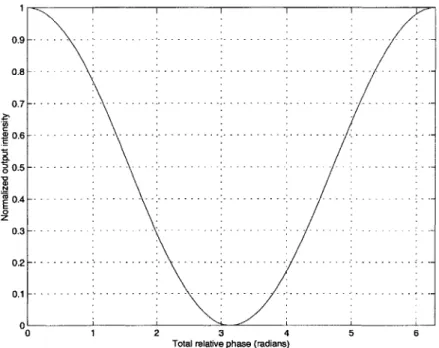
= 2 E S2cos(2 ) 0c Ix cos2 4re)
Because 'I ,ei is linearly related to I, we can control the phase shift between the pulses
in the two arms to cause constructive or destructive interference at the output. The output intensity, in normalized units, is plotted against the relative phase difference in Figure 2-2.
We can easily apply this interferometer to all-optical switching. The presence or absence of the control pulse can determine whether or not a signal pulse is transmitted. In the absense of control pulses, both arms are linear. Suppose we adjust L, and L", so that, when no control pulses are present, a 7r relative phase shift is added between
1
0.2
0.1
Total relative phase (radians)
5
Figure 2-2: Normalized output intensity of the nonlinear
ter versus <rl.a.
Mach-Zehnder
interferome-the signal pulses in interferome-the two arms. The pulses destructively interfere at interferome-the output and no signal pulses are transmitted. On the other hand, when control pulses are present and when they are intense enough to induce another 7r phase shift between the pulses in the two arms, the signal pulses in the two arms constructively interfere at the output and are transmitted.
Although simple, the nonlinear Mach-Zehnder design has several problems. First, there may be undesirable and uncontrollable asymetries between the two arms. If the carrier wavelength is 1550 nm, then even small variations in temperature between the two arms could affect the difference in their optical path lengths enough to move the bias point of the switch from ON to OFF. Even acoustic vibration from ambient sound could noticeably affect the switch's performance. Active electronic control of the path length could stabilize these asymetric variations, but it adds hardware and complexity. Another problem with the nonlinear Mach-Zehnder interferometer arises when the medium used in the nonlinear arm does not have an instantaneous response. The ultrafast nonlinear interferometer discussed in Section 2.2.2 uses a semiconductor
0.9 0.8 0.7 2? 0.6 0 w 0.5 . 0 z 0.3 6 -- --- -- ------- - - -- --- --- --- --- --- --- --- --- --- --- --- - - - --- --- - - - -- - -- - - ---- - - - - - - --- - - - - --- - -- -- - --- - --- --- - ---- --- ..- ..-.-- ------ ---- -- - -- -- - - -- - --- --- ---- ---- - --- ---- - - - - --- ------- -- - - -- -U
based nonlinear medium that is described by several effects that range in speed from several femtoseconds to several nanoseconds [22]. The long carrier density relaxation will affect switching if the nonlinear response exceeds one bit length. A control pulse might then induce a phase shift both in the pulse it temporally overlaps and in a subsequent pulse. N. S. Patel wrote simulations showing distortion of a 40 Gbit/s pulse stream due to long-lived index changes in a semiconductor based nonlinear Mach-Zehnder interferometer [23].
2.2.2
The Ultrafast Nonlinear Interferometer (UNI)
Many of the problems with the nonlinear Mach-Zehnder interferometer are mitigated if the switch design is changed to the ultrafast nonlinear interferometer shown in Figure 2-3. The UNI is a single arm interferometer (SAI). Rather than having signal pulses propagate through two separate arms, the signal pulse is temporally separated into two pulses, which propagate down a single arm. Therefore, the thermal and acoustic variations that limite the nonlinear Mach-Zehnder interferometer's perfor-mance do not affect the UNI. The UNI has been demonstrated to switch at rates up to 100 Gbit/s without the active control that would be necessary in the Mach-Zehnder [24].
The UNI can modulate the data pattern of the control pulses onto the signal pulses. The signal pulses enter at the left of the UNI. The first polarization con-troller (PC1) is set so that each signal pulse is linearly polarized and passes max-imally through the polarizer (PZR1). A length of birefringent fiber, aligned at 45 degrees to the linearly polarized signal pulses, separates each signal pulse into two equally-intense temporally-separated orthogonal polarizations. The control pulses, of a different wavelength than the signal pulses, are coupled into the UNI in a 50/50 coupler. They temporally overlap one of the two signal pulse polarizations. These control pulses will be used to switch the signal pulses ON or OFF. The semiconductor optical amplifier (SOA) is used as the nonlinear medium in the UNI. In the SOA, a control pulse induces a phase shift in the signal pulse polarization that it temporally overlaps. The two polarization components of the signal pulse are recombined
tem-Signal BRF BRF
Figure 2-3: The Ultrafast Nonlinear Interferometer (UNI) separates the signal pulse into orthogonal components. The control pulse induces a phase shift in one compo-nent; both components are then interfered at PZR2. The components are polarization
controllers 1, 2, and 3 (PCi, PC2, and PC3), polarizers 1 and 2 (PZR1 and PZR2),
birefringent fiber (BRF), semiconductor optical amplifier (SOA), and band pass filter (BPF).
porally in the second length of cross-spliced birefringent fiber and then interfered in the polarizer (PZR2). The control pulses are then filtered out in the band pass filter (BPF).
SOAs provide a very high nonlinear index of refraction, with rt2 on the order of
10-6 m2
/W
[22]. In contrast, optical fibers typically have an n2 on the order of
10-20 m2
/W
[21]. In optical switching applications, the SOA's high nonlinear index of refraction can be an important advantage. At 100 Gbit/s, pulses are separated in time by only 10 ps. In an SOA, which can be less than 1 mm long, only one or two pulses will be propagating in the nonlinear medium at any point in time. If we use fiber as the nonlinear medium, then its low nonlinear index force would require hundreds of meters of fiber to acheive the desired nonlinear phase shift. A 500 m length of fiber, when used as the nonlinear medium in an all-optical switch, creates a logical latency of 250,000 bits simultaneously propagating in the fiber. Although this latency could cause problems in many applications of all-optical switching, it does2.3
Relevant Physical Properties
In this section, we will discuss several physical properties of optical fiber that are relevant to all-optical nonlinear switching. First, we will discuss chromatic dispersion and its effects on the propagation of Gaussian pulses in optical fibers. Then, we will derive the nonlinear wave equation used to describe pulse propagation in an optical fiber, the nonlinear Schrbdinger equation (NLS). Last, we will discuss loss and birefringence and their role in all-optical switching and regeneration.
2.3.1
Dispersion
A short optical pulse contains many frequencies. In fact, the shorter the pulse is in
time, the wider it is in the frequency spectrum. In a dispersive medium, each fre-quency component propagates down the fiber at a different speed, leading to pulse distortion. These dispersive effects are very important in deciding which nonlinear medium to select for an all-optical switch or regenerator. We can express these disper-sive effects mathematically by defining a frequency dependent propagation constant,
O(w). After propagating a distance z, the component of the field at w, E(w), receives
a phase shift of /(w)z to become E(w)eO(w)z.
We consider first the case of the dispersion of a Gaussian pulse, because this problem can be solved analytically. We expand O(w) in a Taylor series around the carrier frequency wo:
1
O(w) = 0 + 01(W - wo) + I02(W - wo)2
+
(2.32)2
The constants 0#, in 2.32 are equal to |-
#0
is an initial and constant phase shift on the pulse. /1 is the group delay and determines the velocity of the center ofthe Gaussian pulse envelope.
#2
is called the group velocity dispersion (GVD) and,the pulse at z = 0 as
E(z = 0, t) = Eo exp 2t2 In 2 e iWot
where we have dropped the c.c. because dispersion is a linear effect, making the c.c. term is unnecessary.
(FWHM) is
This optical pulse's full width at half its maximum intensity
TFWHM =TO.- (2-34)
The propagation of the Gaussian pulse in a dispersive medium is easily solved in the frequency domain, so we calculate the Fourier transform of this field:
E(z = 0,w) = E(z = 0, t)e~Ct dt
-AL:
(2.35)
EO exp 2t21 In 2 e(w-w)t dt.
T2
We can easily solve this equation by completing the square in the exponent and consulting standard integral tables [25]:
TO
E(z = 0,w) = T exp
2 2ir ln2 ex
S-(
WO)2T281.2 (2.36)
Thus, the spectrum of the Gaussian pulse is another Gaussian pulse in w with a spectral intensity FWHM of
4ln2
AWFWHM TO (2.37)
In a purely dispersive medium, in which nonlinear effects are negligible, the field,
after propagating a distance L, is given by
E(z = L, w) = E(z = 0,w)e (w)L
- E~ = ~(2.38) = (z =0, W)e i,8+,3 ('-WO)+ '12 (-WO)+--. ]L
where we have substituted Equation 2.32 into O(w). We neglect terms higher than
#2
because in fiber 03 only becomes significant for very short pulses. Then we have from Equation 2.38E(z = L, w) = E(z = 0, w) e0+8P-WO)+-, -WO)]L
T0 To2 i 2 L 2
O exp - (W_ WO)
2 27rn2 2 epn 8 In2 2 (2.39)
+ i#1L(w - wo) + ioL].
Equation 2.39 is still a Gaussian pulse with the same spectral intensity FWHM given in Equation 2.37. So the spectrum of the pulse has the same envelope, but now has a phase shift equal to
#(w)L.
We take the inverse Fourier transform of Equation 2.39 to see how the pulse evolves in time at z = L:E(z = L, t) = j E(z = L, w)eiwt dw
T____ )
[
-(-- 1L)2To21
(2.40)2 = e i(3oLwot)
eo
exp n OI2 /2-,r In 2 2In 2 T04 + 4#2 L2
where
#
is a phase factor given by-(02 L -- t)2
0(t, z = L) = 1. (2.41)
4
0
_ j0As can be seen in Equation 2.40, the pulse is still a Gaussian, although a new phase factor is present, and the pulse's width has changed. We now make several important definitions related to the coefficients,
/n,
in the propagation constant that will help us to understand the physical significance of each coefficient. First, the phase velocityof the pulse, v4 = wo//3, is the speed at which the carrier frequency propagates
through the medium. Second, the group velocity, v. = 1/#1 is the speed at which the pulse envelope propagates through the medium. Last, we call
#2
the group velocity dispersion, which is related to the rate at which the pulse broadens in a second order dispersive medium.We can justify the definition for the phase velocity, v, by looking at the factor
ei(floz-ot) of Equation 2.40 and noticing that a point of constant phase exists at
/Oz - wot = 0, so vp = dz/dt = wo/#o. This exponential factor is the underlying
carrier freqency. We can justify the other definitions by looking at the argument of the exp in Equation 2.40:
-(t - 1z)2T2
n4/3 )(2.42)
21n2 $
+
4#Z2)To justify the definition of the group velocity, we note that the center of the pulse
exists where t - / 1z = 0 and so, v. = dz/dt = 1/#1. To justify the group velocity
dispersion, we note that /2 influences the pulse width. A larger
#2
implies a largerdenominator in Equation 2.42 and, therefore, a wider gaussian in Equation 2.40. It is also useful to calculate the intensity FWHM, as we did in Equation 2.34:
2In 2 _T4
TFWHM = T1n2 2 + 42Z2 (2.43)
To 4(ln 2)2
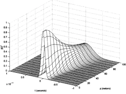
In Figure 2-4 we plot a Gaussian pulse propagating in a second order dispersive medium. As can be seen in the plot and in Equation 2.40, the pulse broadens and its peak intensity drops as the pulse propagates farther in fiber. This distortion, caused
by the second-order dispersion, has a significant effect on the choice of nonlinear
medium for the all-optical switch or regenerator. For example, the decreased peak intensity of the pulse reduces the effect of the nonlinear index of refraction, which is the principle on which all switches in this thesis are based. The lower intensity causes
a smaller phase shift, forcing the use of a longer nonlinear medium.
0.9 -0.7 0.6 0.5 -- 0.4--- 0.3--00 1 60 0.5 -40 X 10 -0520 t (seconds) 0 z (meters)
Figure 2-4: Dispersion induced broadening of a Gaussian pulse in an optical fiber. the signal pulses are separated temporally into two orthogonal polarizations. Ideally, the separation is larger than the pulse width. If it is not, as may happen because of dispersive broadening, the two orthogonally polarized pulses may induce unwanted phase shifts in each other. In the UNI, this problem is solved by using an SOA with high nonlinearity and a short interaction length in order to decrease the dispersive effects. But if we consider using optical fiber as the nonlinear medium, as we will later in this thesis, we must use longer interaction lengths. The design of any fiber based all-optical switch must account for the long interaction lengths and dispersive effects of the fiber.
2.3.2
The Nonlinear Schrodinger Equation
In many cases in fiber optics, the dominant physical effects are second-order disper-sion and the nonlinear index of refraction. Both of these effects are included in the nonlinear Schr6dinger equation (NLS), a wave equation often used in modelling pulse propagation down an optical fiber. Here we provide an outline of the derivation of the NLS. For a more thorough development see Boyd [20].
First, we assume that the electric field can be represented as a slowly-varying envelope, A(z, t):
E(z, t) = A(z, t)e(Ooz-Wot) + c.c. (2.44) where we assume the wave propagates in the z direction with propagation constant
00 = wofii-2. As before, we define the Fourier transform as
E(z, w) = E(z, t)e-' dt. (2.45)
The one-dimensional wave equation is
02E
0z2 (2.46)
a2 D
-Yo 0 t2 = 0.
Now we relate D and E by the constitutive relation
D(z, w) = c(w)E(z, w) (2.47)
where the dielectric constant E includes both the linear and nonlinear components. In the Fourier domain, Equations 2.46 and 2.47 yield
O2g
z 2 - Po E M( W 2 k = 0 . (2.48)
We take the Fourier transform of Equation 2.44 and assume propagation in the +z direction only to get
E(z, w) = A(z, w - wo)efoz + A*(z, -w - wo)e-5 0z
(2.49) ~ A(z, w - wo)eoz
and make the slowly varying envelope approximation (that is, 2A/0z2
= 0), to get
200 az0+ (W2 _ 2
)A
=0.
(2.50)We make another approximation, 32 - e ~ 23o(13 - 0o), and substitute it into
Equation 2.50:
w - wo) - i(# - Oo)A(w - wo) = 0. (2.51)
az
Now we approximate the propagation constant O(w) with a truncated Taylor series that has an extra term, A#NL OC A 2. This extra term accounts for the nonlinear
index of refraction derived in Section 2.1:
O(w) = '30 + (W - wo)O1 + (W - wo)202 + M/NL
1 1 dv 9 w0 (2.52)
= #O + (W - WO)- - (P _ WO)2 g 1,0 + n21W
vg (wo) vg (wo) dw c
By using Equation 2.52, we account for dipsersion up to and including second-order
dispersion and the nonlinear index of refraction. We substitute Equation 2.52 into 2.51 and take the inverse Fourier transform to get
aA DA 1 02A
+0 + 2 -2 - iNLA = 0. (2.53)
We can make a transformation to a moving reference frame,
T = t -
#1z
and U(z, T) = A(z, t), (2.54) to get aU 1 2U =--i 2 + iA3NLU az 2' Or2 (2.55) 1 2U 2 2 5 T2 + U2UIn Equation 2.55 the dispersion is expressed in the first term on the right side of the equation and the nonlinear phase modulation in the second term. The group delay,
#1,
has fallen out of Equation 2.55 because the moving reference frame, given byT = t - 01z, moves with the group velocity of the pulse envelope. In this way, a
pulse at carrier frequency wo remains centered at T = 0. Zakharov and Shabat,
in a monumental paper, discovered exact solutions to the NLS [26]. Nontheless, adding other terms to this equation to account for effects other than dispersion and the nonlinear index of refraction, render the equation unsolvable. Methods exist that solve these equations numerically, and one such method, the split-step Fourier method [21], generated the plot in Figure 2-4.
We can understand Equation 2.55 better by considering two cases: one in which
7 is negligible and the other in which
#2
is negligible. If -y is negligible, we considerpulse propagation in the presence of dispersion alone:
-- 1 2 2U . (2.56)
19Z 2 aT2
Equation 2.56 is solvable by taking its Fourier transform with respect to T:
OU(z w')
'
_1= -i3 2w'2
g(z,
w') (2.57)Oz 2
which has the simple solution
(z,w') =
U(z
= 0, w')e iwz. (2.58)Equation 2.58 describes the effects of second order dispersion, as we discussed in Section 2.3.1. Notice that the magnitude of U(z, w') does not change. Nonetheless, the magnitude of the same function in the time domain, U(z, T), broadens as the pulse propagates. Now, if /2 is negligible, we consider pulse propagation in the presence of
the nonlinearity alone.
au=
Uj2U.(2.59)
Equation 2.59 is solved by considering U in polar form. We can easily verify the solution
U(z, T) = U(z = 0, T)eU-OTz. (2.60)
From Equation 2.60, we see that a phase shift is added to the pulse that is proportional to y and to the intensity of the pulse. This phase modulation is exactly what we expect from Section 2.1, where we discussed the nonlinear index of refraction. Also notice that, unlike the case above with just the dispersion term, the magnitude of the time
domain pulse, IU(z, T)I, does not change. But, the magnitude of the same pulse in
the frequency domain does change.
In single mode fiber (SMF), only the HE,, mode is excited. Nonetheless, if z is the direction of propagation, then the electric field can be considered polarized in either the x or y direction to good approximation. Thus, even single mode fiber supports two different modes of polarization [21]. Equation 2.55 does not account for two possible polarizations or loss in the fiber. To include these effects, we must use a coupled set of two partial differential equations:
A i O 2 +A = i(|Ax|2 + |Ay|2) Ax +
A*A e-2iAez (2.61)
2 &T2 +2A 3YIx 3 x AY~i/
MAY
i 22
+1a
~yL~
2 +2 ~I-x-12'\ UA*2 2iAflz.
+ 3 12 + AY = i-(|Ay2 |Ax|2)Ay + A*'-2s7 (.2
O9z 2 2T 3 ~ ' 3 1
Y1
X- x 2.2
In these equations, a is the loss in the fiber, A, and AY are the electric field envelopes
in the x and y directions, and A0 = #1x - 01y. So, these equations still account for
dispersion and the nonlinear index of refraction, but also account for the fiber loss with a and linear birefringence with A\. The linear birefringence causes each of the polarization components to propagate at different rates. In fact, microbending in the fiber causes the value of the birefringence to change randomly down the length of the fiber, causing the polarization to change quickly and unpredictably. This effect will be important in the design of all-optical regenerators. One last interesting point in